
Heat Transfer Behavior in a Square Duct with Tandem Wire Coil Element Insert
2012-03-22 10:11SmithEiamsaardNarinKoolnapadolandPongjetPromvonge
Smith Eiamsa-ard, Narin Koolnapadol and Pongjet Promvonge,*
1 Department of Mechanical Engineering, Faculty of Engineering, Mahanakorn University of Technology, Bangkok 2 1D0e5p3a0r,t mTehnati loafn dM echanical Engineering, Faculty of Engineering, King Mongkut’s Institute of Technology Ladkrabang,Bangkok 10520, Thailand
1 INTRODUCTION
Heat transfer enhancement techniques of fluid inside the duct of heat exchangers have received serious attentions in many engineering applications, such as thermal power plants, chemical processing plants, air conditioning equipment, refrigerators, radiator for automobiles,etc. To date, attempts have been made to reduce the size and cost of heat exchangers. In general,heat transfer augmentation can be divided into two groups: the passive method, without stimulation from the external power and the active method, requiring extra external power sources. The twisted tape and wire coil turbulators are simple passive techniques for enhancing convective heat transfer in the duct by insertion to promote the redevelopment of boundary layer, and cause enhancement of heat transfer by increasing turbulence and fluid mixing. Therefore, more compact and economic heat exchanger with lower operation cost can be obtained.
For decades, many of the wire coil devices employed for augmentation of laminar or turbulent flow heat transfer have been investigated and discussed.However, few researches for wire coil inserts have been reported in the literature in comparison with those for twisted tape inserts. This has been pointed out by Shojiet al. [1] and Garciaet al. [2]. Some investigations were carried out to determine the effect of the wire coil on heat transfer and friction factor for a long time [3-6]. A comparison of the thermal and hydraulic performances between twisted tape inserts and wire coil inserts was made by Wang and Sunden [7]for both laminar and turbulent flows. They found that the wire coil performs effectively in enhancing heat transfer in a turbulent flow region whereas the twisted tape yields a poorer thermal performance. Yakut and Sahin [8] studied the heat transfer and friction loss characteristics by placing wire coil turbulators in a tube in terms of the shedding frequencies and amplitudes of vortices produced by wire coil turbulators.Ozceyhan [9] examined numerically the conjugate heat transfer and thermal stress in a tube with wire coil inserted under uniform and constant wall heat flux,while heat transfer and pressure drop characteristics in a horizontal double pipe with coil-wire inserts were investigated experimentally by Naphon [10]. Promvonge[11] investigated thermal characteristics of circular- and square-wire coils inserted tubes and found that the wire coil with square cross section provided higher thermal performance than the one with circular cross section.Guneset al. [12] reported the thermal and flow friction characteristics in a circular tube fitted with equilateral triangle cross sectioned wire coil and suggested that detached wire coil was preferable. Recently, the compound turbulators such as twisted tape/swirl generator coupled with wire coil [13-15], combined rib and wire coil/winglet [16-18] were widely interested. The results revealed that the compound devices provide higher heat transfer rate, friction factor and also thermal performance than the wire coil/twisted tape or a single device alone, indicating the synergy effect of both devices.
In the above literature review, most studies are mainly focused on the effects of wire coil inserts on heat transfer and friction characteristics of air/water flows in round tubes only. The investigation on wire coil inserts in square ducts has rarely been reported in the literature. The merit of square duct over round tube is that it has larger surface area to volume ratio, including lower friction loss at similar Reynolds number values. However, its drawback is ineffective heat transfer surfaces at the corners and the wire coil can induce a secondary swirl flow that helps to wash up the flow trapped in the corners leading to better fluid mixing and higher heat transfer rate in the duct. Thus, the main aim of the present work is to extend the experimental data available on wire coil elements inserted into a square duct. Experimental results using air as the test fluid from two types of coil wire elements: full and tandem short-length coils, are presented in turbulent flows ranging fromRe=4000 to 25000. Influences of various relevant parameters such as the full-length coil,1Dand 2Dlength coils and free-space lengths on the Nusselt number and friction factor in a uniform heat flux square-duct are investigated experimentally.
2 EXPERIMENTAL SETUP AND DATA REDUCTION
2.1 Apparatus
The experimental work was conducted in an open-loop experimental facility as shown in Fig. 1.The loop consisted of a circular pipe which connected a high-pressure blower to a settling tank, and an orifice flowmeter was placed in this pipeline. A square channel including a calm section (2000 mm) and a test section was employed after the settling tank. The aluminum tested duct having duct height (H) of 45 mm has a length ofL=1000 mm, with 45 mm inner hydraulic diameter (D=H), 51 mm outer hydraulic diameter (Do=Ho), and 3 mm thickness (t) as depicted in Fig. 2. The wire coil was made of a small steel wire with circular cross-section. The wire coil with 4.9 mm wire thicknesses (w), 39 mm spring pitch, (coil pitch ratio,CR=8) and outer coil diameter of 43 mm was inserted into the square duct by slightly loose fit with the duct wall as suggested in [12]. The tested square-duct was heated by four electrical heater plates attached over duct sides to provide a uniform heat flux boundary condition. The electrical output power was controlled by a variac transformer to obtain a constant heat flux along the entire length of the test duct. The outer surface of the tested duct was well insulated to minimize convective heat loss to the surroundings. The inlet and outlet temperatures of the bulk air were measured at certain points with a multi-channel temperature measurement unit (data logger) in conjunction with the type K thermocouples, calibrated within ±0.2 °C deviation by thermostat before being used (Fig. 1). Thirty thermocouples were tapped on the upper and lower walls and a side wall of the duct to measure the temperature variation around the duct cross section. The average wall temperature was determined based on the type K thermocouples.
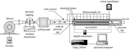
Figure 1 Schematic diagram of experimental apparatus
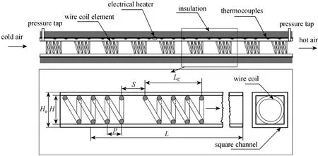
Figure 2 Test duct fitted with wire coil elements
The inlet bulk air at 28 °C from a 1.5 kW blower was directed through the orifice meter to the heat transfer test duct. The airflow rate was measured by an orifice meter which was calibrated beforehand by using both hot-wire and vane-type anemometers. Manometric fluid was used in inclined/U-tube manometers with specific gravity of 0.826 to ensure reasonably accurate measurement of the low pressure drop encountered at low Reynolds numbers. Also, the pressure drop of the heat transfer test duct was measured with inclined/U-tube and digital manometers at an isothermal condition. The volumetric airflow rates from the blower were adjusted by varying motor speed through an inverter. During the experiments, the bulk air was heated by an adjustable electrical heater wrapping along the test duct. For each test run, it was necessary to record the data of temperature, volumetric flow rate and pressure drop of the bulk air at steady state conditions. The Reynolds number of the bulk air was varied from 5000 to 25000. The various characteristics of the flow and the Nusselt number were based on the average of duct wall temperature and inlet-outlet air temperature.
The uncertainty in the data calculation was based on Ref. [19]. The maximum uncertainties of nondimensional parameters were ±5% for Reynolds number, ±5% for Nusselt number and ±7% for friction factor. The uncertainty in the axial velocity measurement was estimated to be less than ±7%, and about ±5% for pressure drop, whereas the uncertainty in temperature measurement at the duct wall was about ±0.5%.
2.2 Data reduction
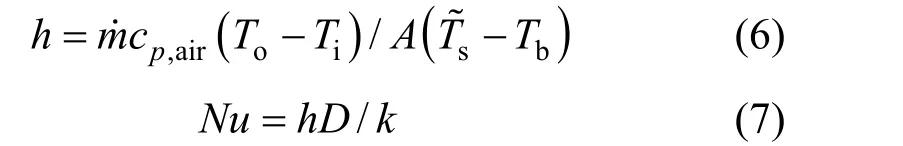
In the present work, air was used as the test fluid.The steady state heat transfer rate is assumed to be equal to the heat loss in the test duct:

in which

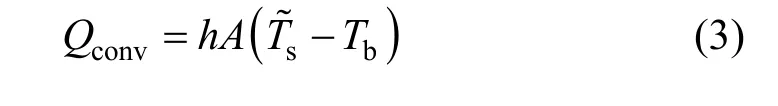
The heat supplied by electrical heater plates in the test duct is found to be 3% to 5% higher than the heat absorbed by the fluid for thermal equilibrium test due to convection and radiation heat losses from the test duct to surroundings. Thus, only the heat transfer rate absorbed by the fluid is taken for internal convective heat transfer coefficient calculation. The convection heat transfer from the test duct can be written by
where
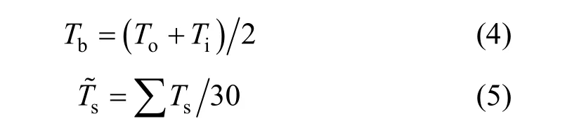
where for a constant heat flux, the average surface temperaturesT˜ can be calculated from 30 points of the local surface temperatures,sT, lined equally apart between the inlet and the exit of the test duct. The average heat transfer coefficient,hand the average Nusselt number,Nuare estimated as follows:
The Reynolds number is given by

Friction factor,f, can be written as
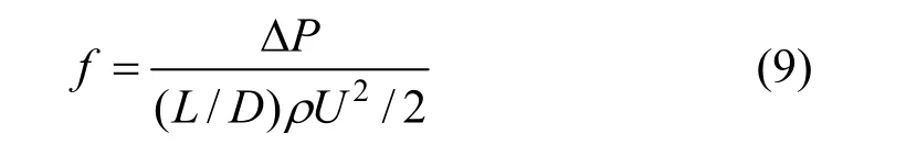
in whichUis mean air velocity in the duct. All thermo-physical properties of air are determined at the overall bulk air temperature from Eq. (4).
For a constant pumping power,

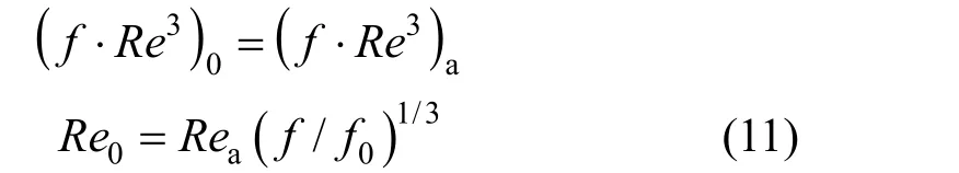
and the relationship between friction and Reynolds number can be expressed as:
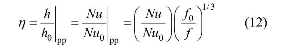
The thermal enhancement factor,η, defined as the ratio of the,hof an augmented surface to that of a smooth surface,h0, at an identical pumping power is suggested by Webb [20]:
3 RESULTS AND DISCUSSION
3.1 Verification of smooth duct
The present experimental results on heat transfer and friction characteristics in a smooth wall square duct are first validated in terms of Nusselt number and friction factor. The Nusselt number and friction factor obtained from the present smooth duct are, respectively,compared with the correlations of Dittus-Boelter and Gnielinski for Nusselt number, and of Blasius and Petukhov for friction factor found in the open literature [21] for turbulent flow in circular ducts.correlation of Dittus-Boelter,

correlation of Gnielinski,
correlation of Blasius,
correlation of Petukhov,
Fig. 3 (a) and 3 (b) shows, respectively, a comparison of Nusselt number and friction factor obtained from the present work with those from correlations of Eqs.(13) and (14). In the figure, the present results agree very well within ±5% with published friction factor and Nusselt number correlations [21].
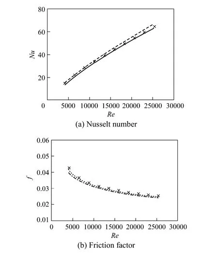
Figure 3 Verification of Nusselt number and friction factor for smooth square duct Dittus-Boelter; × Present smooth duct; Gnielinski;Petukhov; Blasius
3.2 Effect of wire coil inserts
The present experimental results on heat and flow friction characteristics in a uniform heat flux duct with wire coil element inserts are presented in the form of Nusselt number and friction factor as shown in Figs. 4 and 5, respectively. The wire coil turbulator yields considerable heat transfer enhancement with a similar trend in comparison with the smooth duct, and the Nusselt number from both coils increases for rising Reynolds number. This is because the wire coil turbulator interrupts the development of the boundary layer of the fluid flow and increases the degree of flow turbulence. It is worth noting that the full length coil provides higher heat transfer than the short length ones for all Reynolds number values, as can be seen in Fig. 4. The average increases in heat transfer rate for using the full, 1Dand 2Dlength coils atS/D=1 are,respectively, found to be about 140%, 116% and 118%higher than the smooth duct. The use of the full length coil also shows a higher heat transfer rate than those of the 1Dand 2Dcoils atS/D=1 around 7% and 9%depending on Reynolds number values, respectively.
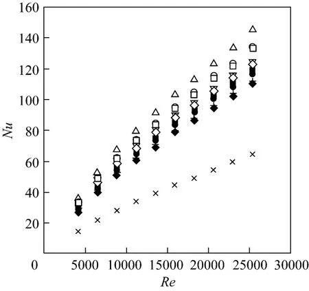
Figure 4 Variation of Nusselt number with Reynolds number for various wire coils△ full-length coil; ○ 2D coil, S/D=1; □ 1D coil, S/D=1;▽ 2D coil, S/D=2; ◇ 1D coil, S/D=2; ■ 2D coil, S/D=3;● 1D coil, S/D=3; + 2D coil, S/D=4; ◆ 1D coil, S/D=4;× smooth duct
Figure 5 presents the variation of friction factor with Reynolds number for the full, 1Dand 2Dlength coils. In the figure, it is apparent that the use of coil elements leads to a substantial increase in friction factor above the smooth duct. Since the coil elements pretended as a second duct in the test duct, the contact of working fluid with the surface area of test duct is higher due to longer flow path and residence time,resulting in higher friction loss. The mean friction factor of the full length coil is found to be higher than that of the 1Dand 2Dcoils atS/D=1 around 12% and 5%, respectively.
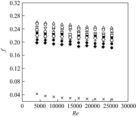
Figure 5 Variation of friction factor with Reynolds number for various wire coils△ full-length coil; ○ 2D coil, S/D=1; □ 1D coil, S/D=1;▽ 2D coil, S/D=2; ◇ 1D coil, S/D=2; ■ 2D coil, S/D=3;● 1D coil, S/D=3; + 2D coil, S/D=4; ◆ 1D coil, S/D=4;× smooth duct
3.3 Effect of space ratio
The variation of the Nusselt number with Reynolds number for four free space ratios (S/D=1, 2, 3 and 4) of 1Dand 2Dcoils is displayed in Fig. 4. In the figure, the heat transfer increases considerably with the Reynolds number. A close examination reveals that for using the 1Dand 2Dcoils, the heat transfer rate at the lower space ratio (S/D=1) is greater than that at the higher one over the Reynolds number range studied. This is because the turbulence intensity and the flow path obtained from the lower space ratio are higher and longer than that from the higher one. AtS/D=1, 2, 3 and 4, the average increases in heat transfer rate for the 1Dand 2Dcoils are, respectively,about 118%, 100%, 90% and 80%; and around 120%,104%, 95% and 85% over the smooth duct.
The variation of friction factor with Reynolds number for various free space ratios of 1Dand 2Dcoil elements is also depicted in Fig. 5. In the figure, the friction factor tends to decrease with the rise of Reynolds number and space ratio values. The increase in friction factor with the swirl turbulent flow created by the coil, however, is much higher than that with the smooth duct flow. This can be attributed to the dissipation of dynamic pressure of the fluid due to higher surface area and the act caused by the swirl flow. As expected, the friction factor obtained from the smaller space ratio is higher than that from the higher space ratio. The increases in friction factor of using the 1Dand 2Dcoils atS/D=1, 2, 3 and 4 are in a range of about 5.5-8.5, 5-7.8, 4.6-7.2 and 4.5-6.8 times and about 6-8.9, 5.7-8.6, 5.3-8.2 and 4.7-7.6 times the smooth duct, respectively.
3.4 Performance evaluation
The Nusselt number ratio,Nu/Nu0, plotted against the Reynolds number is illustrated in Fig. 6. From the figure, the Nusselt number ratio tends to slightly decrease with the rise of Reynolds number for all turbulators. The full-length coil gives the highest Nusselt number ratio of about 2.43 at the lowest Reynolds number while the 2Dcoil performs better than the 1Dcoil at a givenS/Dvalue. Also, the lowerS/Dyields higher Nusselt number ratio than the larger one. It is noted that theNu/Nu0of the 1Dcoil is nearly the same as the 2Dcoil at correspondingS/Dvalue. The averageNu/Nu0values for the full length coil and the tandem coil ofS/D=1, 2, 3 and 4 are, respectively, about 2.4; and 2.18, 2.05, 1.9 and 1.8.
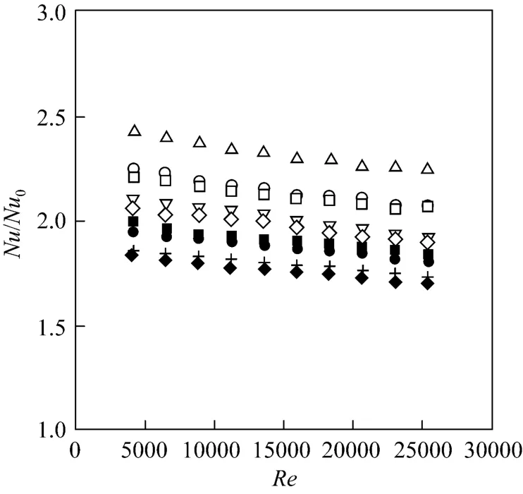
Figure 6 Variation of Nusselt number ratio, Nu/Nu0 with Reynolds number△ full-length coil; ○ 2D coil, S/D=1; □ 1D coil, S/D=1;▽ 2D coil, S/D=2; ◇ 1D coil, S/D=2; ■ 2D coil, S/D=3;● 1D coil, S/D=3; + 2D coil, S/D=4; ◆ 1D coil, S/D=4
Figure 7 presents the variation of friction factor ratio,f/f0, with the Reynolds number. It is observed that the friction factor ratio tends to increase slightly with rising Reynolds number. The full length coil provides a higher increase in the friction factor ratio than the 1Dand 2Dlength ones at similar operating condition. The meanf/f0values for the full length coil and the short length ones ofS/D=1, 2, 3 and 4 are, respectively, about 8.4; and 7.8, 7.2, 6.8 and 6.5. This indicates that the use of the free space length is not efficient to reduce friction loss significantly. This is likely from the fact that the wire coil used in the current work is at optimum coil pitch and thickness ratios at suggested in [6]. If the wire coil pitch is at other values, the result may be different.
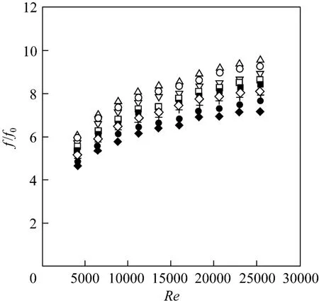
Figure 7 Variation of friction factor ratio, f/f0 with Reynolds number△ full-length coil; ○ 2D coil, S/D=1; ▽ 2D coil, S/D=2;□ 1D coil, S/D=1; ■ 2D coil, S/D=3; ◇ 1D coil, S/D=2;+ 2D coil, S/D=4; ● 1D coil, S/D=3; ◆ 1D coil, S/D=4
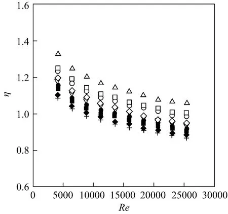
Figure 8 Variation of enhancement efficiency with Reynolds number△ full-length coil; □ 1D coil, S/D=1; ○ 2D coil, S/D=1;◇ 1D coil, S/D=2; ▽ 2D coil, S/D=2; ● 1D coil, S/D=3;■ 2D coil, S/D=3; ◆ 1D coil, S/D=4; + 2D coil, S/D=4
Figure 8 shows the variation of thermal enhancement factor with Reynolds number for all wire coils.For all, the experimental data are compared at identical pumping power. It can be observed in the figure that the enhancement factors generally are above unity only for the full and short length coils atS/D=1, indicating that the use of theS/D=0 or 1 wire coil element inserts is advantageous over the smooth square duct. The otherS/Dwire coil element inserts provide the enhancement factor above unity only for lower Reynolds number regime. The enhancement factor tends to decrease with the rise of Reynolds number but increases with the reduction of the space ratio,especially at zero space ratio (or full length coil). The enhancement factor of the full length coil is about 10%-25% higher than that of the short length one,depending on the S/D value. The maximum enhancement factors of the full-length, 1Dand 2Dcoils atS/D=1 are found to be about 1.33, 1.25 and 1.24 at lower Reynolds number, respectively.
4 CONCLUSIONS
An experimental study has been carried out to examine the airflow friction and heat transfer characteristics in a square duct fitted with tandem wire coil element turbulators for the turbulent regime,Re=4000 to 25000 andPr=0.7. The use of wire coil elements causes a high pressure drop increase,f/f0=4.5-9.5,which depends mainly on space ratio andRevalues,and also provides considerable heat transfer augmentations,Nu/Nu0=1.7-2.45. However, Nusselt number augmentation tends to decrease slightly with the rise of Reynolds number. If wire coils are compared with a smooth duct at a constant pumping power, an increase in heat transfer is obtained especially at low Reynolds number. Although fairly large differences have been observed among the analyzed coil wires, their performance evaluated is quite similar: atRe=4000,η≈ 1.24-1.33 and atRe=25000,η≈ 1.03-1.1 for usingS/D=0-1. The use of tandem wire coil elements can reduce significantly the friction loss in the duct but the heat transfer rate is also decreased. Therefore, the full-length coil should be applied instead of the tandem short length one to obtain higher heat transfer and performance, leading to more compact heat exchanger.The best operating regime for the wire coil turbulator is found at lower Reynolds number where the thermal enhancement factor is about 1.33.
NOMENCLATURE
1 Shoji, Y., Sato, K., Oliver, D.R., “Heat transfer enhancement in round tube using coiled wire: Influence of length and segmentation”,HeatTransfer-AsianRes., 32 (2), 99-107 (2003).
2 García, A., Vicente, P.G., Viedma, A., “Experimental study of heat transfer enhancement with wire coil inserts in laminar-transitionturbulent regimes at different Prandtl numbers”,Int.J.Heat Mass Transfer, 48, 4640-4651 (2005).
3 Uttarwar, S.B., Rao, M.R., “Augmentation of laminar flow heat transfer in tubes by means of coiled wire inserts”,Trans.ASME, 107,930-935 (1985).
4 Chiou, J.P., “Experimental investigation of the augmentation of forced convection heat transfer in a circular tube using spiral spring inserts”,Trans.ASME, 109, 300-307 (1987).
5 Prasad, R.C., Shen, J., “Performance evaluation using exergy analysis—Application to wire-coil inserts in forced convection heat transfer”,Int.J.Heat Mass Transfer, 37 (15), 2297-2303 (1994).
6 Ravigururajan, T.S., Bergles, A.E., “Development and verification of general correlations for pressure drop and heat transfer in single-phase turbulent flow in enhanced tubes”,Exp.Therm.Fluid Sci.,13, 55-70 (1996).
7 Wang, L., Sunden, B., “Performance comparison of some tube inserts”,Int.Comm.Heat Mass Transfer, 29 (1), 45-56 (2002).
8 Yakut, K., Sahin, B., “The effects of vortex characteristics on performance of coiled wire turbulators used for heat transfer augmentation”,Appl.Therm.Eng., 24 (16), 2427-2438 (2004).
9 Ozceyhan, V., “Conjugate heat transfer and thermal stress analysis of wire coil inserted tubes that are heated externally with uniform heat flux”,EnergyConvers.Manage., 46, 1543-1559 (2005).
10 Naphon, P., “Effect of coil-wire insert on heat transfer enhancement and pressure drop of the horizontal concentric tubes”,Int.Comm.Heat Mass Transfer, 33 (6), 753-763 (2006).
11 Promvonge, P., “Thermal performance in circular tube fitted with coiled square wires”,Energy Convers.Manage., 49 (5), 980-987(2008).
12 Gunes, S., Ozceyhan, V., Buyukalaca, O., “Heat transfer enhancement in a tube with equilateral triangle cross sectioned coiled wire inserts”,Exp.Therm.Fluid Sci., 34 (6), 684-691 (2010).
13 Promvonge, P., “Thermal augmentation in circular tube with twisted tape and wire coil turbulators”,Energy Convers.Manage., 49 (11),2949-2955 (2008).
14 Eiamsa-ard, S., Nivesrangsan, P., Chokphoemphun, S., Promvonge,P., “Influence of combined non-uniform wire coil and twisted tape inserts on thermal performance characteristics”,Int.Comm.Heat Mass Transfer, 37 (7), 850-856 (2010).
15 Promvonge, P., “Thermal enhancement in a round tube with snail entry and coiled-wire inserts”,Int.Comm.Heat Mass Transfer, 35(5), 623-629 (2008).
16 Saha, S.K., “Thermal and friction characteristics of turbulent flow through rectangular and square ducts with transverse ribs and wire coil inserts”,Exp.Therm.Fluid Sci., 34 (5), 575-589 (2010).
17 Promvonge, P., Khanoknaiyakarn, C., Kwankaomeng, S., Thianpong,C., “Thermal behavior in solar air heater channel fitted with combined rib and delta-winglet”,Int.Comm.Heat Mass Transfer, 38 (6),749-756 (2011).
18 Promvonge, P., Chompookham, T., Kwankaomeng, S., Thianpong,C., “Enhanced heat transfer in a triangular ribbed channel with longitudinal vortex generators”,Energy Convers.Manage., 51 (6),1242-1249 (2010).
19 ANSI/ASME, Measurement Uncertainty, PTC 19. 1-1985, Part I,USA (1986).
20 Webb, R.L., “Performance evaluation criteria for use of enhanced heat transfer surfaces in heat exchanger design”,Int.J.Heat Mass Transfer, 24, 715-726 (1981).
21 Incropera, F.P., DeWitt, D.P., Bergman, T.L., Lavine, A.S., Introduction to Heat Transfer, 5th edition, John Wiley & Sons, USA (2006).
 Chinese Journal of Chemical Engineering2012年5期
- Chinese Journal of Chemical Engineering的其它文章
- Ammoximation of Cyclohexanone to Cyclohexanone Oxime Catalyzed by Titanium Silicalite-1 Zeolite in Three-phase System*
- Adsorption and Desorption of Praseodymium (III) from Aqueous Solution Using D72 Resin*
- Turbulent Characteristic of Liquid Around a Chain of Bubbles in Non-Newtonian Fluid*
- Isolation and Characterization of Heterotrophic Nitrifying Strain W1*
- Recovery of Tungsten (VI) from Aqueous Solutions by Complexationultrafiltration Process with the Help of Polyquaternium*
- Optimizing the Chemical Compositions of Protective Agents for Freeze-drying Bifidobacterium longum BIOMA 5920*