
EFFICIENT NUMERICAL METHOD FOR DYNAMIC ANALYSIS OF FLEXIBLE ROD HIT BY RIGID BALL
2012-10-08 12:10XuChunlingWangXinwei
Xu Chunling,Wang Xinwei
(1.State Key Laboratory of Mechanics and Control of Mechanical Structures,Nanjing University of Aeronautics and Astronautics,Nanjing,210016,P.R.China;2.Beijing Institute of Nearspace Vehicle’s Systems Engineering,Beijing,100076,P.R.China)
INTRODUCTION
Impact dynamics of flexible solids is important in engineering practice and has been received much attention.The dynamic analysis is a challenging task since analytical solutions are only applicablefor a few simple cases.Therefore,some studies have focused on how to develop efficient numerical methods for obtaining solutions[1-6].
Recently,the discrete singular convolution(DSC),proposed by Wei,has emerged as a local spectral method to combine the accuracy of global methods with the flexibility of local methods[7].The method can handle complex geometry and boundary conditions in many applications[8-9],including solving some challenge mechanical problems.However,DSC has not been applied for analysis on impact dynamics of flexible solids yet. Therefore,one of the objectives of the present work is to explore the utility of DSC for the impact dynamic analysis.The other objective is to investigate the efficiency of various numerical methods for dynamic analysis of a cantilever flexible rod hit by a rigid ball at its free end.The problem seems rather simple but is really difficult to numerically obtain an accurate time-history impact force[3]. Several methods,including the conventional finite element(FE)method,the DSC algorithm,and the spectral finite element(SFE)method,and one proposed modeling strategy,the improved spectral finite element(ISFE)method,are investigated.
1 BASIC EQUATION
A cantilever flexible rod hit by a rigid ball with a speed of v0 at its free end(Fig.1)is considered.According to St.Venant’s principle for a bar, the equation that governs the propagation of axial elastic waves in a bar is

where E is Young’s modulus,d the mass density of the bar material,u(x,t)the displacement of the bar,p(x,t)the distributed axial force per unit length,A the cross-sectional area of the bar,x the Cartesian coordinate located in the center axis of thebar,and t the time.In Fig.1,L is the length of the bar.

Fig.1 Axial impact of cantilever bar hit by rigid ball
Boundary conditions

Define the functional C as
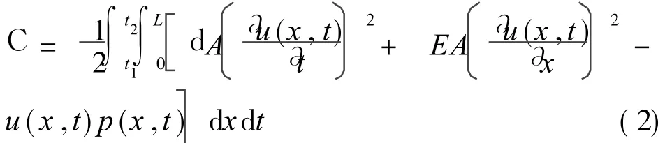
Then Eq.(1)can be obtained by the wellknown Lagrange’s equations.
2 NUMERICAL METHOD
Three well-known numerical methods,including DSC algorithm,the conventional FE method and SFE method are involved.For FE method,a two-node two-degree-of-freedom bar element[4]is used.Lumped mass matrix is used for the explicit time integration algorithm.For completeness,the formulations of the other two methods are briefly summarized.
2.1 DSC algorithm
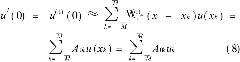
In DSC algorithm,a function u(x)and its j th order derivative with respect to x are approximated via a discretized convolution[7]as


There are many kernels available.Due to its simplicity,the non-regularized Lagrange’s Delta sequence kernel is adopted in the present study.DSC algorithm is called DSC-LK[8]or simply DSC. The non-regularized Lagrange’s Delta sequence kernel,already discretized,is given as
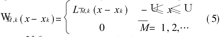
where U≤L,and LM,k(x)is the Lagrange interpolation function defined as

Elements of the higher order differentiation matrix,WT(j
,W)(xm-xk),can be computed by


where A0kand B0kare the weighting coefficients of the first-and the second-order derivative with respect to x.
In terms of DSC,Eq.(2)together with the boundary conditions can be written as

2.2 SFE method
The procedures of deriving the stiffness and mass matrices for a SFE are similar to the conventional FE method[5].A crucial difference from the higher order conventional FE is the distribution of the node in the element. For conventional element, nodes are uniformly distributed.For SFE,nodes are distributed nonuniformly. For example, the Gauss-Labatto-Legendre(GLL)points arefrequently used as the nodes in a bar element.Takean eight-nodeeightdegree-of-freedom bar element as an example,the displacement is given as

where ue(ai)is the i th nodal displacement and Ni(a)(-1≤a≤ 1)is the shape function which is the Lagrange polynomial.
Similar to the conventional FE method,Eq.(2)is used to formulate the elemental mass and stiffness matrices[M]e,[K]eand work equivalent load vector{F}e.They can becalculated numerically as
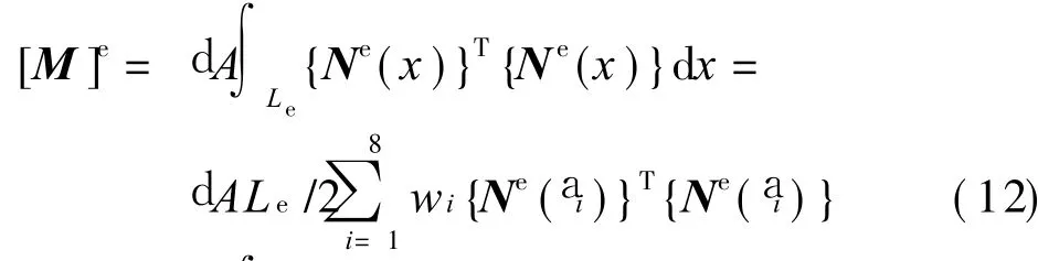


where pe(x)is a distributed load in the element,and{Be}is calculated by
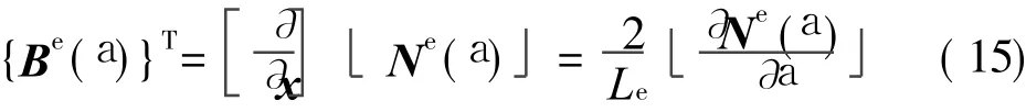
Since a i are GLL points,the weight wi is computed by
where P7(a) is the 7th order Legendre polynomial.
In terms of FE or SFE,the following matrix equation is obtained
It should be mentioned that the mass matrix[M]is a diagonal matrix.This property allows a crucial reduction of the cost of the numerical integration[5].
3 MODELING STRATEGY AND SOLUTION PROCEDURE
To test the efficiency of various numerical methods and modeling strategies,a rigid ball with m=d AL impacts on a cantilever bar(Fig.1)is considered, since analytical solution is available[1].Let thewave speed c becalculated by c=T?hefirst and the second impacts occur at time t=1.534T and t=2.128T,respectively,where T(T=2L/c)is the fundamental period of the bar.
For conventional FE method,the bar is modeled by 400 equal length elements resulting in 401 degrees of freedoms.For SFE method,the bar is modeled by 100 equal length SFEs resulting in 701 degrees of freedoms.For DSC,the bar is equally divided by 300 segments resulting in 301 degrees of freedoms andis set as 16 for the present study.In other words,the total number of grid points N is 301.One additional modeling strategy,ISFE is proposed.The bar is modeled by oneconventional FEbar element at its freeend and 99 equal length SFEs resulting in 695 degrees of freedoms.
For FE,SFE and ISFE,all elements in the force vector in Eq.(17)is 0 except its first element.F1(t)=f(t). However,F1(t)=2f(t)/(Δx)in Eq.(10).In other words,it is assumed that the concentrated force f(t)at the free end is uniformly distributed over the small portionΔx/2,whereΔx=L/(N-1).Usually N≫in modeling elastic wave propagations and impact for both accuracy and computational efficiency considerations.
Due to the diagonal form of the mass matrix for all three methods investigated,the set of the second-order ordinary differential equations in time can be integrated by employing the central finite difference method[10], an explicit but conditional stable method for efficiency considerations.The integration procedures are listed below for readers’references.
Step 1 Compute{u}-1by using the given initial conditions as
综上所述,针对一氧化碳中毒迟发型脑病患者应用依达拉奉联合高压氧进行治疗效果显著,具有较高的临床应用价值。
{u}-1={u}0-Δt{v}0+ Δt2/2{a}0 (18)where{v}={∂u(x,t)/∂t}is the velocity vector,{a}={∂2u(x,t)/∂t2}the acceleration vector, Δt the time increment,{u}0 and{v}0 are the known initial conditions,and{a}0 can be determined by the equation of motion.
Step 2 Compute the"effective load"at time tn as

where[K]is a banded matrix.In programming,this property should be used to save CPU time.Step 3 Determine the displacement at time tn+1 as

where[M]-1can beeasily obtained since[M]is a diagonal matrix.
Step 4 Compute the acceleration and the velocity at time tn as
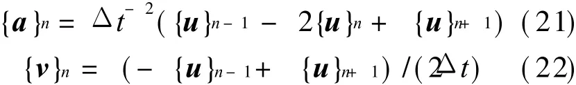
Repeat Steps 2-4 until time reaches the specified value.
4 RESULT AND DISCUSSION
For comparison with known solutions,the material and geometrical parameters are chosen as:E=2.1× 10¹¹N/m2,d=7.9× 103kg/m3,L=0.3 m,A=9×10⁻⁴m2,and m=2.133 kg.The initial velocity of the rigid ball v0 is 1 m/s.The time incrementΔt is taken as 10-8s in the numerical simulations.
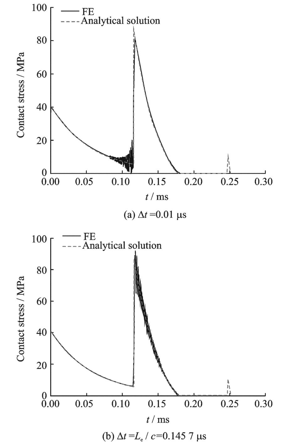
Fig.2 Comparison of time-history contact stress by FE method and analytical solution
Fig.3 shows the comparison of time-history contact stress obtained by SFEand the analytical solutions.Although the average results are close to the analytical solutions and the second impact instant is correctly captured,the simulations are polluted by the computational noise. The data should be filtered by a low-pass digital filter if more accurate solution is required.
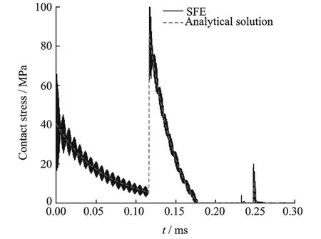
Fig.3 Comparison of time-history contact stress by SFE and analytical solution
Fig.4 shows the comparison of time-history contact stress obtained by DSCand the analytical solutions.It is seen that both the first and the second contact instants are correctly captured.The results agree well with the analytical solutions. It should be pointed out that the solution accuracy depends on bothand N.

Fig.4 Comparison of time-history contact stress by DSCand analytical solution
Results shown in Fig.5 are obtained by the ISFE modeling strategy. Figs.5(a-c) correspond to L FE=L SFE,L FE=5L SFE,and L FE=L SFE/5,where L FE is the length of the conventional bar element and LSFE(0.003 m)the length of SFE.Comparing to data shown in Fig.3,the ISFE modeling strategy reduces the computational noise greatly.However,the proper selection of L FE is important for the solution accuracy.It is obvious that L FE should not be greater than L SFE.
The time-history of the displacement at the contact point is shown in Fig.6.It can be seen
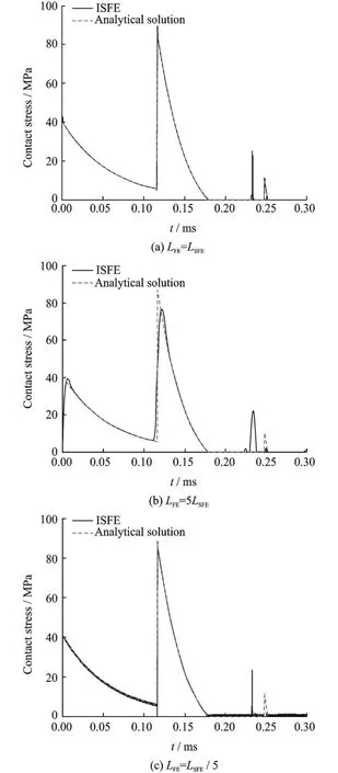
Fig.5 Contact stress time-history by ISFE
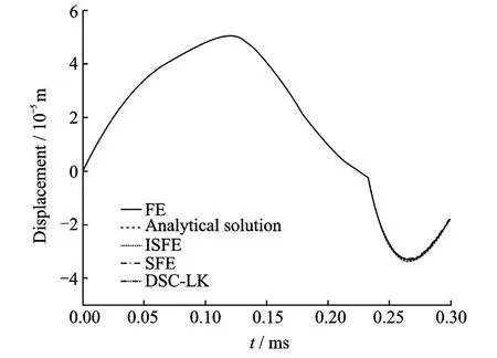
Fig.6 Displacement at x=0
that numerical results of all methods and modeling strategies are close to each other and well agree with those of the analytical solutions.In other words,the displacement is not as sensitiveas contact stress or acceleration to the used numerical methods,since it is obtained by doubleintegrations of acceleration.
For comparison purpose,Table 1 lists the CPU time used in the simulations for all methods and strategies.Table 2(where NA means not available)lists the simulated time at which the impact occurs and compares it with the exact one.Overall speaking,if L FE is properly selected,ISFE yields the most accurate results than all other methods and DSC yields accurate results with the least computational effort.

Table 1 Comparison of CPU time consumed by f our methods(Δt=10-8 s)
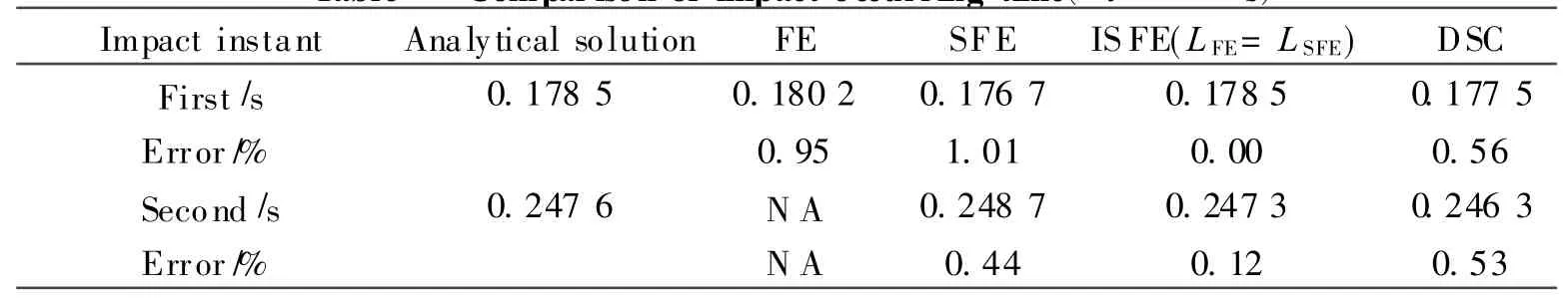
Table 2 Compar ison of impact occurring time(Δt=10-8 s)
5 CONCLUSION
The dynamic response of a cantilever bar hit by a rigid ball is obtained by using DSC,FE method, SFE method, and ISFE method,Numerical results are compared to the known analytical solutions to show the efficiency and the accuracy of the methods.Results indicate that the ISFE method with a proper length of conventional FE yields the most accurate time-history contact stress among the four models investigated.It is also found that DSC,used to investigate the impact problems for the first time,can be an alternative method for solving collision problems.
[1] Escalona J L,Mayo J,Dominguez J. A new numerical method for thedynamic analysis of impact loads in flexible beams[J].Mechanism and Machine Theory,1999,34(5):765-780.
[2] Shen Yunian, Yin Xiaochun. A dynamic substructure technique for the transient dynamics of non-homogeneous flexible bars with impact[J].Engineering Mechanics,2008,25(11):42-47.(in Chinese)
[3] Liu Jinyang. A substructure technique for the contact-impact of a flexible body with a rigid ball[J].Chinese Journal of Computational Mechanics,2001,18(1):28-32.(in Chinese)
[4] Ding Suiliang,Hong Jiazhen.Dynamic analysis of impact loads in flexible multibody systems by FEM[J].Journal of Shanghai Jiaotong University,2003,37(12):1927-1930.(in Chinese)
[5] Kudelaa P,Krawczuk M,Ostachowicz W.Wave propagation modeling in 1D structures using spectral finite elements[J].Journal of Sound and Vibration,2007,300(1/2):88-100.
[6] Komatitsch D,Martin R,Tromp J,et al.Wave propagation in 2-D elastic media using a spectral element method with triangles and quadrangles[J].Journal of Computational Acoustics,2001,9(2):703-718.
[7] Wei G W. A new algorithm for solving some mechanical problems[J].Computer Methods in Applied Mechanics and Engineering,2001,190(15):2017-2030.
[8] Wei G W,Zhao Y B,Xiang Y.The determination of natural f requencies of rectangular plates with mixed boundary conditions by discrete singular convolution[J].International Journal of Mechanical Sciences,2001,43(8):1731-1746.
[9] Wang X,Wang Y,Xu S.DSC analysis of a simply supported anisotropic rectangular plate [J].Composite Structures,2012,94(8):2576-2584.
[10]Subbaraj K,Dokainish M A.A survey of direct time-integration method in computational structural dynamic-I: Explicit methods[J]. Computers&Structures,1989,32(6):1371-1386.
猜你喜欢
今日农业(2019年13期)2019-08-12
知识经济·中国直销(2017年10期)2017-11-07
摄影之友(影像视觉)(2017年1期)2017-07-18
中国药业(2014年19期)2014-05-17
天津冶金(2014年4期)2014-02-28
海洋世界(2014年2期)2014-02-27
祝您健康(1989年1期)1989-12-30
祝您健康(1987年6期)1987-12-31
 Transactions of Nanjing University of Aeronautics and Astronautics2012年4期
- Transactions of Nanjing University of Aeronautics and Astronautics的其它文章
- RELIABILITY EVALUATION MODEL BASED ON DATA FUSION FOR AIRCRAFT ENGINES
- MATHEMATICAL MODEL OF 4He QUANTUM INTERFEROMETER GYROSCOPE
- TASK ALLOCATION BASED ON PHEROMONE
- DEVELOPMENT AND PRELIMINARY APPLICATION OF OBJECTIFYING SYSTEM FOR TCM COLOR INSPECTION
- FLIGHT CONFLICT FORECASTING BASED ON CHAOTIC TIME SERIES
- FPGA BASED REAL-TIME VIDEO IMAGE ACQUISITION AND STORAGE SYSTEM