
Expansion characteristics of twin combustion gas jets with high pressure in cylindrical filling liquid chamber*
2013-06-01 12:29XUEXiaochun薛晓春YUYonggang余永刚ZHANGQi张琦
水动力学研究与进展 B辑 2013年5期
关键词:张琦
XUE Xiao-chun (薛晓春), YU Yong-gang (余永刚), ZHANG Qi (张琦)
School of Energy and Power Engineering, Nanjing University of Science and Technology, Nanjing 210094, China, E-mail: xiaochun13476@163.com
(Received April 12, 2013, Revised July 9, 2013)
Expansion characteristics of twin combustion gas jets with high pressure in cylindrical filling liquid chamber*
XUE Xiao-chun (薛晓春), YU Yong-gang (余永刚), ZHANG Qi (张琦)
School of Energy and Power Engineering, Nanjing University of Science and Technology, Nanjing 210094, China, E-mail: xiaochun13476@163.com
(Received April 12, 2013, Revised July 9, 2013)
Abtract: To deal with the problem of how to control the interior ballistic stability in the bulk-loaded liquid propellant gun, the expansion and mixing process of the twin combustion-gas jets with high temperature and pressure in a liquid medium is studied in the cylindrical filling liquid chamber. A series of the jet expansion shapes is obtained by using a high-speed photographic system. The influences of the jet pressure on the jet expansion shape are discussed. Based on the experiments, the three-dimensional mathematical model is established. The expansion processes of the twin gas jets in the liquid medium are simulated by means of fluent to get the pressure, density, temperature, velocity contours and evolutionary process of vortices. Results show that the jet external outline and tops are all irregular. The Kelvin-Helmholtz instability is shown in the whole expansion process. The numerical simulation results of the axial displacement of the twin gas jets in liquid agree well with the experiment.
twin combustion gas jets with high pressure, turbulent mixing, jet expansion shape, numerical simulation
Introduction
The combustion gases with high temperature and high pressure are generated by converting the chemical energy into the heat energy in the combustion process of the liquid propellant gun in response to the projectile motion with a certain initial velocity. The Bulk-loaded Liquid Propellant Gun (BLPG) has an igniter at the breech end and works on the principles of the fluid dynamic instability, including the two main mechanisms, generally referred to as the Taylor instability and the Helmholtz instability of the gas-liquid interface, to break the liquid propellant and form a certain burning surface. However, this breaking mechanism by the fluid instability has a great randomness, which is just the key reason that makes it difficult to control the combustion process of the BLPG. Macpherson and Bracuti[1]reviewed the performance variabilities observed in the BLPG, including the frequent overpressures and the occasional gun system failures, which are basically due to the fact that the combustion process in the BLPG depends on the hydrodynamic instabilities developed during the liquid propellant ignition and combustion process, rather than on the predetermined solid propellant grain geometry to define the burning surfaces. Based on these observations, Adams and Barth[2,3]carried out experimental studies of the new methods of controlling the combustion process. Dai[4]revealed the evolutionary processes of the back-attack of the gas jet by means of visualization experiments. Xu[5]tracked the gas-liquid interface by adopting the VOF model and carried out numerical simulations on the flow field of the combustion-gas jets in water without considering the vaporization. Wang et al.[6]analyzed the underwater supersonic gas jets and found that the gas-liquid interfaces of the jets are unstable owing to the influences of the turbulent flow, the two-phase mixture and the Kelvin-Helmholtz instability. In 2005, Nguyen and Evans[7]studied the impact jet flow of the gases injected in the liquids and successfully tracked the gas-liquid interface, which is of a practical value. Based on the fluid mechanics, Yu and Qi[8-10]did experimental and numerical studies of the mixing characteristics of the single gas jet and liquid in a stepped-wall and rectangular structure. In addition, the gas jets are also verywidely applied in the engineering technology, including underwater welding and cutting, underwater missile launch[11-14].
Based on the planar combustion structure[15], with the multipoint ignition process as the background, this paper discusses the turbulent mixing characteristics of the twin combustion-gas jets and the liquid in a cylindrical chamber. The experiments and three-dimensional numerical simulations are carried out, to establish a theoretical basis for studying the control methods of the interior ballistic stability of BLPG.
1. Experimental device and principles
The experimental studies are carried out on the expansion processes of the twin combustion-gas jets and the liquid in a cylindrical chamber. Figure 1 is the sketch of the experimental device, which is composed of a combustion chamber of high pressure, two straight nozzles, a deflagrating power, the copper seal film, the liquid medium and a cylindrical chamber. The cylindrical chamber is full of the liquid medium. The deflagrating power in the combustion chamber is ignited by the pulse electric ignition system to generate the combustion gases with high temperature and high pressure. When the pressure of the combustion gases exceeds the breaking pressure of the copper seal film, the combustion gases inject into the cylindrical filling liquid chamber through two nozzles and then the turbulent mixing occurs between the gas and the liquid. The processes of the gas-liquid mixing and the expansion shapes of the Taylor cavities are recorded by means of a high-speed photographic system. The experimental device is placed upward and the liquid medium is water.
Fig.1 The sketch of experimental device
The shape and the intensity of the jet are controlled by adjusting the explosive payload of the deflagrating power and the thickness of the copper seal film. In the experiment, the diameter of the cylindrical observation chamber is 0.064 m and the whole length is 0.110 m.
2. Experimental results
2.1The expansion processes of twin combustion-gas jets in cylindrical chamber
Figure 2 is the sequence map of the twin combustion-gas jets in the cylindrical filling liquid chamber. The experimental conditions are as follows: the injection pressure is 18 MPa, the nozzle diameter is 0.0008 m, and the nozzle separation distance is 0.016 m.
Fig.2 Expansion sequence of twin gas jets in the cylindrical filling liquid chamber
As can be seen from Fig.2, the twin combustion gases eject into the cylindrical chamber at 1 ms and the expansion shapes of the jets are relatively regular. At 2 ms, one observes the weak entrainment and interference between two jets, resulting in a trend of their approaching each other. However, the outer contours of the twin jets are in zigzag shapes as a result of the Kelvin-Helmholtz instability. As the twin combustiongas jets expand, the jet heads reach the exit of the cylindrical chamber at 7 ms. While a part of liquid at the bottom of the cylindrical chamber is not yet in the Taylor cavities, it can still absorb the heat energy of the combustion gases in the Helmholtz mixing. The above results show that, when the twin combustiongas jets with high temperature and high pressure eject into the combustion chamber in the BLPG, twin Taylor cavities are formed as a result of the impacting effect on the liquid surface. With the Taylor cavities expanding, the liquid propellant at the projectile base is compressed until the projectile obtains a certain muzzle velocity. Then the Taylor cavities expand to the projectile base quickly, so the residual liquid propellant in the wall surface and the bottom of the combustion chamber is mostly involved in the combustion in the Helmholtz mixing at this time. Just because of the inherent instability of the Helmholtz mixing between the gas and the liquid, the combustion randomness in the BLPG is enhanced, resulting in a dramatic pressure pulsation in the combustion chamber.
2.2The influence of injection pressure on twin combustion-gas jets in liquid medium
The experiments are carried out under differentinjection pressures to analyze the influences of the injection pressure on the twin combustion-gas jets in the liquid medium. First, the axial displacement is determined by taking the average position of the front-end fluctuating interface of the jets at different instants and the axial expansion velocities of the Taylor cavities are obtained from the axial displacement data, as shown in Fig.3. Then, with the velocity curve fitting, the axial acceleration curve is obtained by differentiation of the axial velocity fitting curve, as shown in Fig.4. The experimental conditions are as follows: the nozzle diameter is 0.0008 m, the nozzle separation distance is 0.020 m, and the injection pressures are, respectively, 10.8 MPa, 18 MPa and 28.8 MPa.
Fig.3 The relation ofv-tunder different jet pressures
Fig.4 The relation ofa-tunder different jet pressures
As seen from the typical experimental processes of the twin combustion-gas jets in the liquid medium, the axial velocities and the values of the accelerations go up with the increase of the injection pressure at first, as shown in Fig.3 and Fig.4. A major result of this phenomenon is that the power source from the combustion-gas is enhanced when the injection pressure increases. Before the injection pressure reaches 18 MPa, the axial velocity of the twin combustion-gas jets increases substantially with the injection pressure, and with a further increase of the injection pressure, the axial velocity changes little and the axial acceleration tends to be constant in the later period.
3. Theoretical model
3.1Physical model
Based on the experiments of the twin combustion-gas jets in the liquid medium, the assumptions of the physical processes are made as follows: (1) The expansion process of the twin gas jets in the liquid medium is a three-dimensional unsteady process, (2) Thek-εmodel is used to calculate the turbulent mixing effect between the gas and the liquid, (3) The combustion-gas jets are approximated as ideal gas jets, (4) The chemical reaction of the gas and the liquid is not considered, (5) The secondary influencing factors such as the gravity of the combustion gases are ignored.
3.2Mathematical models
Based on above assumptions, the controlling equations are as follows:
(1) Equation of continuity
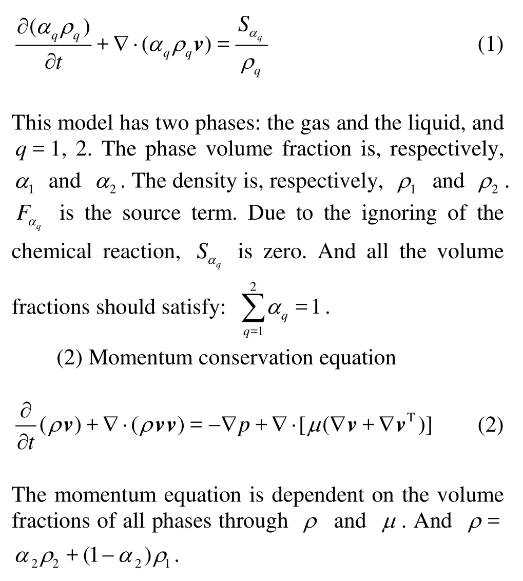
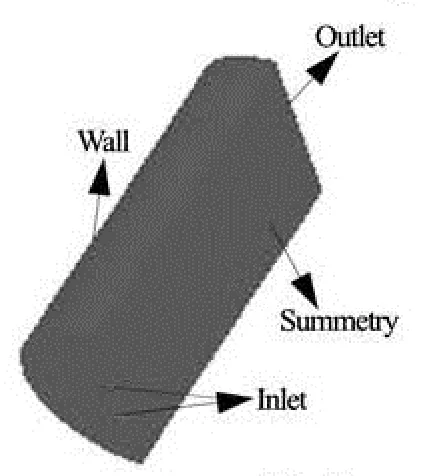
Fig.5 Computational domain
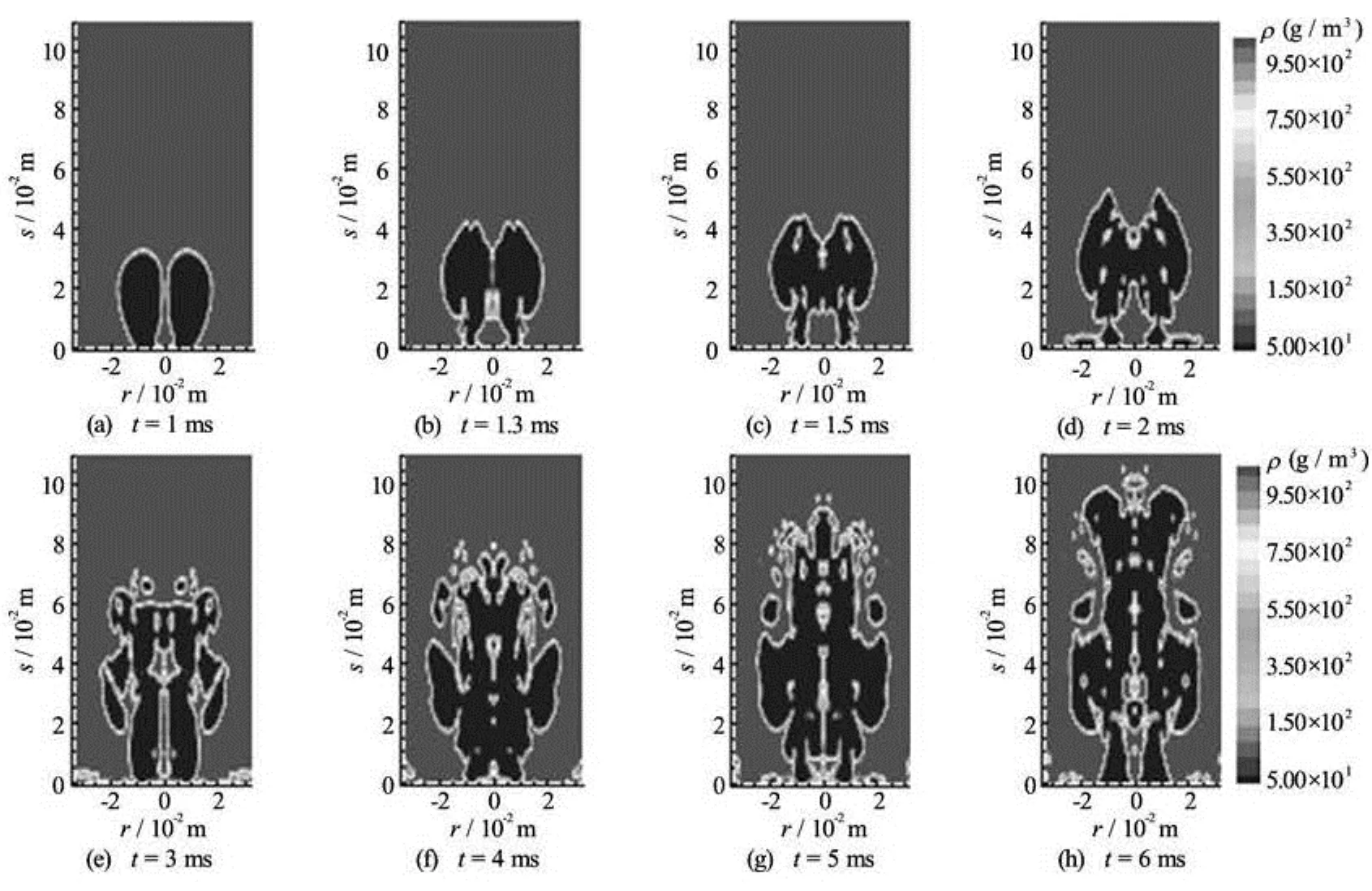
Fig.6 The isodensity of twin gas jets (g/m3)
(3) Energy conservation equation
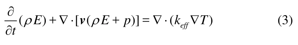
In the VOF model, the energy,E, and the temperature,T, are treated as mass-averaged variables
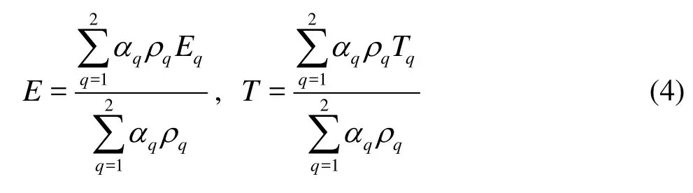
whereEqof each phase is the specific heat of that phase with the shared temperature. The propertiesρandkeff(effective thermal conductivity) are shared by the phases.
(4) Equation of state

(5) Turbulent flow equation (the turbulence kinetic energy,k, and its rate of dissipation,ε, are obtained from the following transport equations)
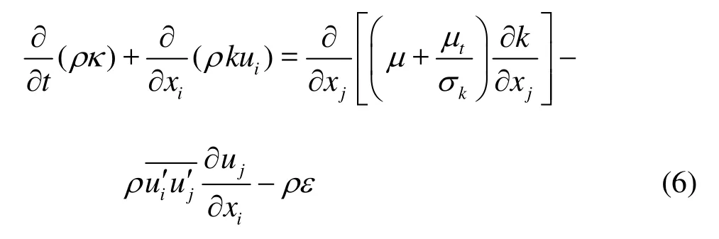
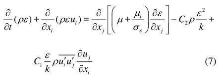
wherekσandεσare the turbulent Prandtl numbers forkandε, respectively.is the Reynolds stress that expresses the influence of pulsation on the time averaged flow. And the turbulent (or eddy) viscosity,bμ, is computed fromkandεas follows
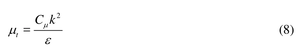
whereCμis a constant.
The model constants take the following default values
3.3Initial and boundary conditions
The computational domain is shown in Fig.5. There are four boundary conditions which are, respectively, the inlet pressure boundary, the outlet pressure boundary, the wall and the symmetry planes. Thecomputational domain is initialized with the liquid phase parameters as follows:T=T0=300 K,p=p0=101325 Pa. The inlet conditions are determined by the experiment:T=T1=2000 K,p=p1= 18 MPa. The outlet of the cylindrical chamber is connected with the atmosphere, so the outlet conditions are the atmospheric parameters:T=T2=300 K,p=p2=101325 Pa.
4. Numerical simulation
Based on the experiment, the numerical simulation on the twin combustion-gas jets in the liquid medium is carried out by Fluent with the nozzle separation distance of 0.016 m, the nozzle diameter of 0.0008 m and the liquid medium of water. The pressure-based solver is used, the spatial attribute is the three-dimensional space and the attribute of time is the unsteady flow in the simulation. The VOF model is used to calculate the multiphase flow. In addition, the size of mesh on the twin nozzles is 0.0002 m and the size of the other computational domain is 0.0006 m. And finer grids are used to test the grid independence. The numerical results of the axial displacement among different grid resolutions see little difference with an estimated maximum error of 2%.
4.1The density distribution
Figure 6 shows the isodensity map of the twin combustion-gas in the cylindrical chamber. As can be seen from Fig.6, the Taylor cavities are spherical in shape at 1ms and the surfaces of the Taylor cavities are smooth. At 2 ms, the turbulent fold appears at the heads of the jets due to the Taylor instability by the compression effect of the liquid phase and the necking at the bottom of the jets is generated as a result of the entrainment between the gas and the liquid. As the twin jets expand, the twin Taylor cavities converge into one. At 3 ms, the shape of Taylor cavities becomes irregular and the liquid is broken into smaller droplets in the intense gas-liquid mixing. On the one hand, this phenomenon, promotes the release rate of the combustion-gas heat, on the other hand, the randomness of the twin combustion-gas jets in the liquid is enhanced. So the positive feedback mechanism between the Taylor cavities and the Kelvin-Helmholtz instability works in an unmanageable level. As time goes on, a long and narrow gas cavity is formed in the chamber and the turbulent pulsation all appears inside and outside the cavity. The comparison curve of the numerical and experimental values of the axial displacement (that refers to the average position of the frontend fluctuating interface of the jets at different instants) is obtained from the isodensity maps of the numerical simulation and experimental expansion maps, as shown in Fig.7. From Fig.7, it can be seen that they are in good agreement. The numerical simulation, therefore, can reveal the internal characteristics of the gas-liquid turbulent mixing.
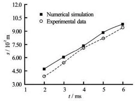
Fig.7 The comparison of the axial expansion displacement
4.2The vortices distribution
Figure 8 shows the evolutionary processes of the vortex field of the twin combustion-gas jets in the liquid medium. As can be seen from the figure, a pair of typical vortices appears near the central axis of the chamber and they move close to each other. Before 3 ms, the heads of the twin vortices expand very quickly, breaking the smoothness in a conical shape. After 2 ms, many small scale vortices with confused and disordered shapes arise in the chamber, which just reflects the intense instability and randomness when the twin combustion-gas jets expand in the cylindrical chamber. Further, a pair of large scale vortices always exists at the bottom of the wall surface, resulting in a reflux area.
4.3The temperature distribution
Figure 9 shows the isothermal map of the twin combustion-gas jets in the liquid medium. As can be seen from the figure, the isothermal lines are dense near the two nozzles and the temperature is higher in the orifices than in other areas. As the jets expand, the gas-liquid interface expands and the heat exchange between the gas and the liquid also increases, resulting in a larger high-temperature zone. The temperature at the bottom of the chamber changes as a result of the backflow effect. In the whole expansion processes, the twin temperature centers always tend to bend to each other and become close enough to merge. With the temperature at the central axis of one nozzle on the section of 0.010 m in the filling liquid chamber as an example, the temperature change is illustrated as follows. At 1ms, the temperature is 1 485 K. At 2 ms, the temperature is 315 K. Compared the two temperature values, it can be seen the temperature decreases sharply with time, which is because the turbulent mixing between the gas-liquid is intense and thus the combustion gases release much energy. At 3 ms, thetemperature is 812 K. At 4ms, the temperature is 346 K. At 5 ms, the temperature is 517 K. At 6 ms, the temperature is 1 440 K. Thus it can be seen the temperature pulsation at the later period of the jet expansion is large with the energy of the combustion gases supplementing and releasing and this is just one reason of the unsteady expansion of the twin combustion gas jets in the cylindrical chamber.
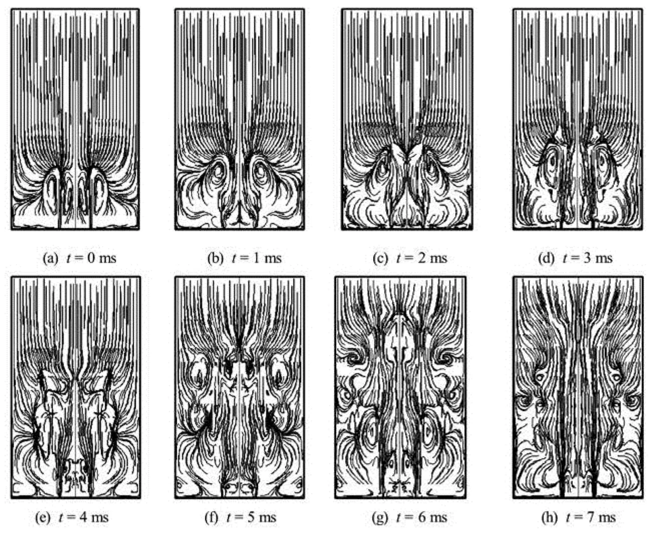
Fig.8 Vortex distribution of twin gas jets
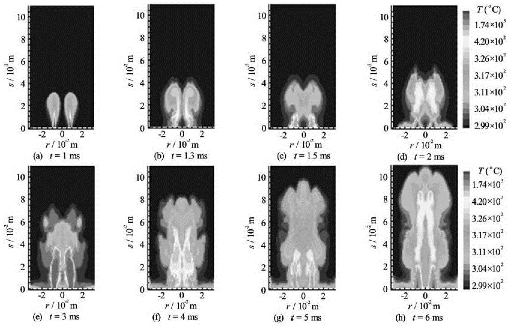
Fig.9 The isotherms of twin gas jets (K)
4.4The pressure distribution
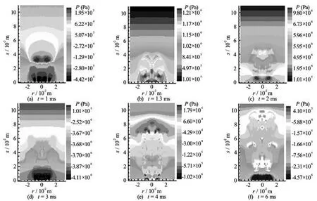
Fig.10 The isobars of twin gas jets (Pa)
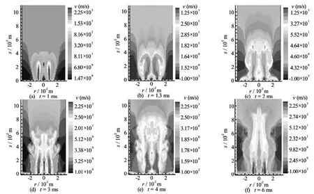
Fig.11 The isovelocities of twin gas jets (m/s)
Figure 10 shows the isobaric chart for the twin combustion-gas jets in the cylindrical chamber. As can be seen from the figure, at 1ms, the pressure distribution is regular with two high pressure areas at the heads of the jets. From the density distribution, it can be seen that the Taylor cavities are in the state of rapid expansion with a negative relative static pressure at the upstream of the high pressure area. As the jets expand forward, the high pressure areas move toward the upstream of the twin jets and the pressure assumes the maximum value near the two nozzles at 1.3 ms-1.5 ms. At 2 ms, the pressure wave has expanded to the whole computational domain and it is clear that the multiple compression waves are formed. The gradient change of the compression wave with time is unsteady. With the density distribution, the necking appears on the twin nozzles at 3 ms.The relative static pressures at the necking location increase to the maximum value. Because the jet velocity in other areas of the jet field is larger than the critical velocity when therelative static pressure is zero, so the relative static pressure is negative at these areas. At 4 ms, the pressure oscillation is especially apparent and the multiple high pressure areas are formed at the head areas of the twin jets. At 6 ms, the heads of the twin jets have expanded to the exit of the chamber. The pressure value is the lowest around the two nozzles, because the local expansion appears on the twin nozzles. The relative static pressures are negative in other areas of the jet field where the jet velocity is larger than the critical velocity when the relative static pressure is zero.
4.5The velocity distribution
Figure 11 shows the isovelocity maps on the twin combustion-gas jets in the liquid medium. As can be seen from the figure, the isovelocity lines are denser near the two nozzles and the velocity reaches the maximum value in the nozzles. As the jets expand forward, the twin isovelocity clusters always go closer to the axis of the chamber as a result of entrainment and interference of each other. After the twin jets converge into one, the velocity distribution becomes more unsteady and is in a conical shape. In the whole expansion processes, the turbulent mixing of the gas and the liquid is intense and the energy exchange is rapid, resulting in a quick decrease of the velocity along the radial and axial directions. The isovelocities take negative values on the wall surface of the chamber because the liquid medium is compressed by the wall surface and the Taylor cavities.
5. Concllusions
Based on the experimental and numerical results, the expansion characteristics of the twin combustiongas jets in a cylindrical filling liquid chamber are obtained as follows:
(1) With the twin combustion-gas jets in the liquid medium, the twin Taylor cavities expand quickly along the axial direction due to lack of restraint from the chamber boundary. The outline of the jets is irregular in a conical shape. The liquid is broken into smaller droplets in the intense gas-liquid mixing. On the one hand, this phenomenon, promotes the release rate of the combustion-gas heat; on the other hand, the randomness of the twin combustion-gas jets in the liquid is enhanced. So the positive feedback mechanism between the Taylor cavities and the Kelvin-Helmholtz instability works in an unmanageable level.
(2) The expansion shapes are related to the injection pressure of the combustion gases. When the injection pressure is larger, the axial velocities and accelerations are all larger. When the injection pressure increases to 18 MPa, the axial velocity of the twin combustion-gas jets rises substantially and the axial acceleration also shows a significant difference.
(3) From the results of the numerical simulation, a pair of large scale vortices appears in the chamber. Because the velocity difference between the gas and the liquid is large, the Kelvin-Helmholtz instability is intense and the turbulent mixing of the gas-liquid is enhanced. Thus, many small scale vortices with confused and disordered shapes are generated in the chamber.
(4) The values of the numerical expansion displacement of the twin combustion-gas jets are in good agreement with the experimental data.
[1] MACPHERSON A. K., BRACUTI A. J. Analysis of gun pressure instability[C]. The 19th International Symposium on Ballistics. Interlaken, Switzerland, 2001, 115-121.
[2] ADAMS M., BARTH E. J. A compressible fluid power dynamic model of a liquid propellant powered rifle[C]. Proceedings of IMECE: International Mechanical Engineering Congress and Exposition. Anaheim, CA, USA, 2004.
[3] ADAMS M., BARTH E. J. Dynamic modeling and design of a bulk-loaded liquid monopropellant powered rifle[J]. Journal of Dynamic Systems, Measurement, and Control, 2008, 130(6): 1-8.
[4] DAI Zhen-qing, WANG Bo-yi and QI Long-xi et al. Experimental study on hydrodynamic behaviors of high-speed gas jets in still water[J]. Acta Mechanical Sinica, 2006, 22(5): 443-448.
[5] XU Xiao-qiang, DENG Jian and REN An-lu. The research on high- speed gas jet of rocket nozzle underwater[J]. Journal of Hydrodynamics, Ser. B, 2005, 17(2): 204-208.
[6] WANG X. L., ITOH M. and SHI H. H. Experimental study of Rayleigh-Taylor instability in a shock tube accompanying cavity formation[J]. Japanese Journal of Applied Physics, 2001, 40(11): 6668-6674.
[7] NGUYEN A. V., EVANS G. M. Computational fluid dynamics modeling of gas jets impinging onto liquid pools[J]. Applied Mathematical Modeling, 2006, 30(11): 1472-1484.
[8] YU Y., CHANG X. and ZHAO N. et al. Study of bulkloaded liquid propellant combustion propulsion processes with stepped-wall combustion chamber[J]. Journal of Applied Mechanics, 2011, 78(5): 1001-1008.
[9] QI Li-ting, YU Yong-gang and PENG Zhi-guo. A 2-D model of energetic gas jet expansion process in liquid and numerical simulation[J]. Chinese Journal of Energetic Materials, 2008, 16(2): 131-137.
[10] MANG S., YU Y. Experiment and numerical simulation for high pressure combustible gas jet expansion process in a bulk-loaded liquid[J]. Explosion and Shock Waves, 2011, 31(3): 300-305.
[11] ZHAO Ke-yu, CHENG Wen and LIAO Wei-li et al. The void fraction distribution in two-dimensional gasliquid two-phase flow using image process method[J]. Journal of Hydrodynamics, Ser. B, 2006, 18(2): 127-134.
[12] RENSEN J., ROIG V. Experimental study of theunsteady structure of a confined bubble plume[J]. International Journal of Multiphase Flow, 2001, 27(8): 1431-1449.
[13] MURAI Y., MATSUMOTO Y. and AMAMOTO F. Three-dimensional measurement of void fraction in a bubble plume using statistic stereoscopic image processing[J]. Experiments in Fluids, 2001, 30(1): 11-21.
[14] EHTERAM M. A., TABIRZI H. B. and AHMADI G. et al. Investigation of fine droplet generation from hot engine oil by impinging gas jets onto liquid surface[J]. Journal of Aerosol Science, 2013, 65(11): 49-57.
[15] YU Y., YAN S. and ZHAO N. et al. Study on expansion process and interaction of high speed twin combustion-gas jet in liquid[J]. Journal of Applied Mechanics, 2010, 77(5): 051404.
10.1016/S1001-6058(13)60423-0
* Project support by the National Science Foundation of China (Grant No. 50776048).
Biography: XUE Xiao-chun (1985-), Female,
Ph. D. Candidate
YU Yong-gang,
E-mail: yyg801@hjust.edu.cn
猜你喜欢
Chinese Physics B(2022年7期)2022-08-01
Chinese Physics B(2022年4期)2022-04-12
Chinese Physics B(2022年3期)2022-03-12
科学与财富(2021年36期)2021-05-10
现代信息科技(2021年21期)2021-05-07
党员文摘(2020年6期)2020-07-16
廉政瞭望·下半月(2020年3期)2020-05-26
杂文选刊(2020年4期)2020-04-19
中国新闻周刊(2019年34期)2019-09-20
美与时代·城市版(2017年3期)2017-05-19

- 水动力学研究与进展 B辑的其它文章
- A one-dimensional polynomial chaos method in CFD–Based uncertainty quantification for ship hydrodynamic performance*
- Numerical analysis of cavitation within slanted axial-flow pump*
- Numerical simulation of hydro-elastic problems with smoothed particle hydrodynamics method*
- Analytic solutions of the interstitial fluid flow models*
- Experimental study of shell side flow-induced vibration of conical spiral tube bundle*
- A streamline approach for identification of the flowing and stagnant zones for five-spot well patterns in low permeability reservoirs*