
Research on fuzzy control technology of DC motor in height automatic adjusting system of CNC cutting machine
2015-11-03 07:02AichengZOUQunyingWANG
机床与液压 2015年3期
Ai-cheng ZOU, Qun-ying WANG
(Guilin University of Aerospace Technology, Guilin 541004, China)
Research on fuzzy control technology of DC motor in height automatic adjusting system of CNC cutting machine
Ai-cheng ZOU*, Qun-ying WANG
(Guilin University of Aerospace Technology, Guilin 541004, China)
Motor control technology is the key factor for height automatic adjusting system of CNC cutting machine. In this paper, one DC motor control technologyis put forward based on the fuzzy control technology and PWM control technology, and the fuzzy controller is designed as well. Experimental results show that the control accuracy and sensitivity of height automatic adjusting system will be improved by using the fuzzy control technology and PWM control technology.
PWM, Fuzzy control, Height automatic adjustment system
1 Introduction
In order to improve the cutting quality and reduce waste generation, it needs to keep the height between cutting torch of CNC cutting machine and the material to be processed on the setting value during the cutting process. Height automatic adjusting system (HAAS) is the key component of CNC cutting machine to realize this function. The control effect of DC motor has direct impact on the accuracy and sensitivity of HAAS. In this paper, one DC motor control technology is put forward based on the fuzzy control technology and PWM control technology, and the fuzzy controller is designedas well in order to effectively improve the control accuracy and sensitivity of HAAS.
2 Control scheme of HAAS
The driving system of HAAS adopts “H-Bridge” and “Bipolar reversible PWM”, which is shown in Fig.1. The “H-Bridge” compose of triodes (V1-V4) and diodes (D1-D4). The MCU analogs the output of PWM, and controls the conduction and cutoff of triodes (V1-V4) in use of the photoelectric coupler. Divided triodes (V1-V4) into two groups, V1 and V4 as one group, V2 and V3 as another group. The two triodes in one group will conduct or cutoff at the same time. The timing diagram of U1 and U2 is shown in Fig.2.
In each cycle of the PWM, the triode V1 and V4 are conducting state, V2 and V3 are cutoff state, when the control signal U1 is high voltage and U2 is low voltage. The armature winding of DC motor will under positive voltage from A to B. The triode V1 and V4 are in cutoff state, V2 and V3 are in conducting state, when the control signal U1 is low voltage and U2 is high voltage. The armature winding of DC motor will under reverse voltage from B to A. The average voltage could be determined as follows:
From the average voltage calculation formula, it is clear that the speed of DC motor is decided byα. The DC motor reversal will reach to the maximum speed whenαis equal to zero. The DC motor is transferred with the maximum speed whenαis equal to 1. The DC motor will stop whenαis equal to 1/2.

Fig. 1 Driving system of DC motor
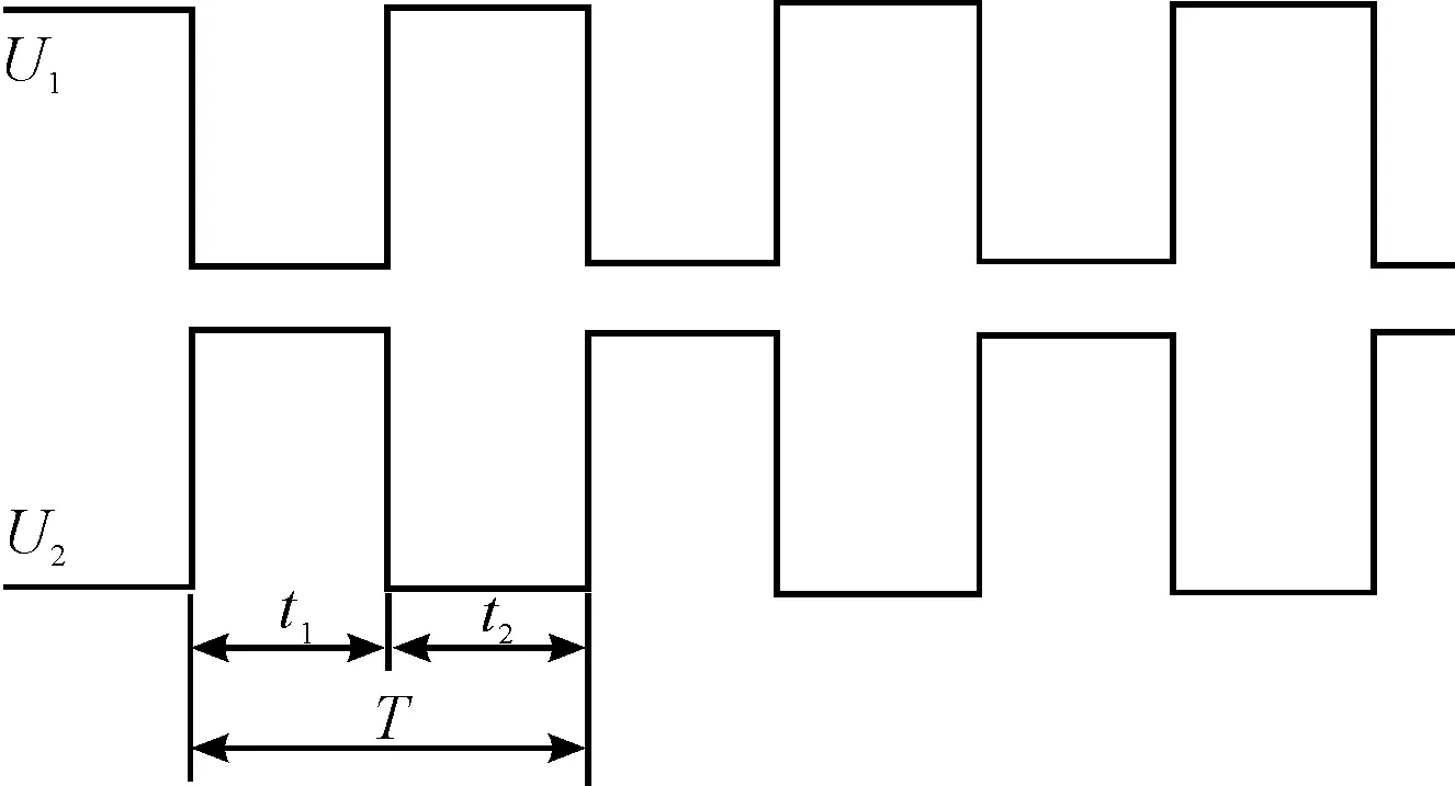
Fig. 2 Timing diagram of U1- U2
3 Fuzzy controller
3.1 Fuzzy control scheme
The following scheme can effectively improve the problems of slow response and low accuracy of HAAS. When adjust the moving speed (V) of the cutting torch dynamically according to the real-time height value (dx) between cutting torch and the material to be processed, the torch will move quickly if the difference between dx and d is large, otherwise, the torch will move slowly. In this way, it can not only adjust the height quickly, but also reduce the error caused by the inertia of the motor at maximum extent. According to this, fuzzy control scheme of DC motor could be designed as shown in Fig.3.

Fig.3 Scheme of fuzzy control
Detect the height value (dx) between cutting torch and the material to be processed in real time, and compare with the initial set value (d). The pitch deviation (e) and the deviation change rate (ec) could be obtained. Converteandecfrom basic domain to the quantification domain, that is to say, multiplyebyKe,andecbyKec. According to the input membership function to calculate the membership degree (EandEC) of each input variable of the fuzzy sets. And then one can get the output fuzzy quantitative value and the actual control value of the PWM.
3.2 Fuzzy process the variables
Fuzzy process the variables are as follows:
1) Pitch deviation (e)
Quantification domain:{-6,-5,-4,-3,-2,-1, 0, 1, 2, 3, 4, 5, 6};
Fuzzy set:{NB,NM,NS,ZO,PS,PM,PB}.
2) Deviation change rate (ec)
Basic domain: initially set pitch of -1% - 1%;
Quantification domain:{-6,-5,-4,-3,-2,-1, 0, 1, 2, 3, 4, 5, 6};
Fuzzy set:{NB,NM,NS,ZO,PS,PM,PB}.
3) Duty ratio (α)
Basic domain: initially set pitch of -0.25 -0.25;
Quantification domain:{-6,-5,-4,-3,-2,-1, 0, 1, 2, 3, 4, 5, 6};
Fuzzy set:{NB,NM,NS,ZO,PS,PM,PB}.
The membership function of the variable is made of triangular distribution. The initial set value (d) is decided by the control requirements. Give the initial valueαas 3/4 when the DC motor is in transferring state. Give the initial valueαas 1/4 when the motor is in reversal state.
3.3 Fuzzy rule table
The fuzzy rule table is the key to the fuzzy controller. Summary the fuzzy control rules according to experience, and establish the fuzzy rules table as shown in Table 1.
Whenα<1/2, the analysis method is similar toα≧1/2.
According to Table 1:
WhenEis NB andECis NB, the deviation has a tendency to increase. In order to eliminate the negative large deviation and inhibition the deviation increasing further as soon as possible, the speed of DC motor should be given as PB. When the deviation change rate is PB, the speed of DC motor should reduce. Otherwise, it will cause bigovershoot.
WhenEis NS, the system is close to the steady state. IfECis NS, the speed of DC motor should be given as PS to suppress the bias change towards negative direction. If the deviation change rate is positive, the system has the trend to eliminate the deviation, the speed of DC motor should be given as NS.
Table 1 Fuzzy rule
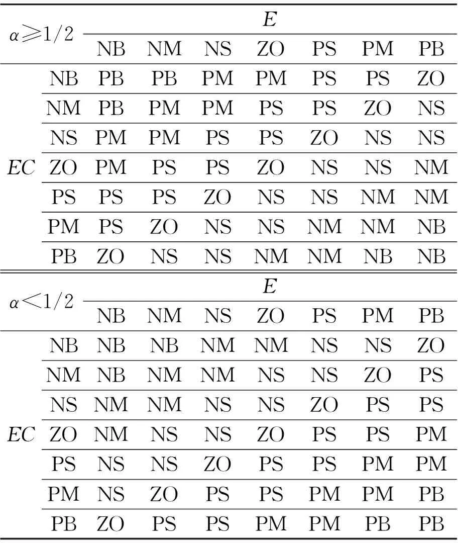
α≥1/2ENBNMNSZOPSPMPBECNBPBPBPMPMPSPSZONMPBPMPMPSPSZONSNSPMPMPSPSZONSNSZOPMPSPSZONSNSNMPSPSPSZONSNSNMNMPMPSZONSNSNMNMNBPBZONSNSNMNMNBNBα<1/2ENBNMNSZOPSPMPBECNBNBNBNMNMNSNSZONMNBNMNMNSNSZOPSNSNMNMNSNSZOPSPSZONMNSNSZOPSPSPMPSNSNSZOPSPSPMPMPMNSZOPSPSPMPMPBPBZOPSPSPMPMPBPB
4 Test analysis
According to the fuzzy control, HAAS is designed and the corresponding experiments are carried out and the test results are shown in Table 2. In this table,Eis the difference betweendxandd,Tis time used by HAAS fromdxtod,Pis precision of the system.
Table 2 Test result

E/mmWithouttheuseoffuzzycontrolT/SP/mmUsefuzzycontrolT/SP/mm<5<1.5<±0.3<0.5<±0.1<10<1.5<±0.3<0.5<±0.1<15<1.5<±0.3<0.5<±0.1<20<2.0<±0.3<0.8<±0.2<30<2.0<±0.3<0.8<±0.3<40<3.0<±0.8<1.0<±0.4<50<3.0<±1.0<1.0<±0.5>50<3.0>2.01.0>0.5
CompareTandPin the columns “Without the use of fuzzy control” and “Use fuzzy control”. It is clear that both theTandPin case of using fuzzy control are lower than those cases without using fuzzy control. Therefore, HAAS has higher precision in case of using fuzzy control, and it could meet the requirements better.
Acknowledgements
This paper is supported by the Guangxi Education Department Fundation (No.2013YB274) and the Guilin University of Aerospace Technology Fundation (No. YJ1047).
[1]Huang X L, Liu J C, Liu H J. Cement Decomposing Furnace Temperature Control Based on the Fuzzy Control Technology [J]. China Building Materials Science and Technology, 2014(3): 54.
[2]Xie C J, Bao H, DU J L. Application of a New Membership Function to Nonlinear Fuzzy PID Controllers with Variable Gains [J]. Information and Control, 2014(3): 264-269.
[3]Hu S S, Weng H H, Weng J X. Design of Fuzzy Controller Based on Primary Tower Temperature Control [J]. Automation and Instrumentation, 2013(6): 35.
[4]He X X, Yan J L, Xu C H. Monitoring and control for sub-sea mud-lift drilling system [J]. Journal of China University of Petroleum, 2012(3): 129-132.
[5]Miao J L, Zou J. Design for Direct Torque Controlled Brushless DC Motor [J]. Application of Electronic Technique, 2011(7): 88-91.
[6]Barlat F, Yoon J W, Cazacu O. On linear transformations of stress tensors for the description of plastic anisotropy[J]. International Journal of Plasticity, 2007, 23: 876-896.
[7]Cazacu O, Barlat F. A criterion for description of anisotropy and yield differential effects in pressure-insensitive metals[J]. International Journal of Plasticity 2004, 20: 2027-2045.
[8]Jiang Y Y, Zhang M, Lee C H. Finite element modeling of self-loosening of bolted joints[J]. ASME Journal of Mechanical Design, 2007, 129: 218-226.
[9]Kan Q H, Kang G Z, Zhang J. Uniaxial time-dependent ratchetting: Visco-plastic model and finite element application[J]. Theoretical and Applied Fracture Mechanics, 2007, 47(2):133-144.
[10]Kang G Z, Gao Q, Yang X J. Uniaxial and non-proportionally multiaxial ratcheting of SS304 stainless steel at room temperature: experiments and simulations[J]. International Journal of Non-Linear Mechanics, 2004, 39(5): 843-857.
[11]Kang G Z. Finite element implementation of visco-plastic constitutive model with strain-range-dependent cyclic hardening[J]. Communications in Numerical Methods in Engineering, 2006, 22(2):137-153.
[12]Kang G Z, Gao Q, Yang X J. A visco-plastic constitutive model incorporated with cyclic hardening for uniaxial/multiaxial ratcheting of SS304 stainless steel at room temperature[J]. Mechanics of Materials, 2002, 34(9):521-531.
[13]Kang G Z. Finite element implementation of visco-plastic constitutive model with strain-range-dependent cyclic hardening[J]. Communications in Numerical Methods in Engineering, 2006, 22(2):137-153.
[14]Chaboche J L. A review of some plasticity and viscoplasticity constitutive theories[J]. International Journal of Plasticity, 2008, 24:1642-1693.
[15]Wang T, Chen G, Wang Y P, et al. Uniaxial ratcheting and fatigue behaviors of low-temperature sintered nano-scale silver paste at room and high temperatures[J]. Materials Science and Engineering a-Structural Materials Properties Microstructure and Processing, 2010, 527(24-25): 6714-6722.
摘要:在FMS物流系统的实时调度优化方面,主要是针对AGV运输展开的调度研究。简要介绍了两种形式的AGV调度策略:基于遗传算法(GA)的AGV调度、基于粒子群算法(PSO)的AGV调度;将模型及调度优化思想以具体的实例进行验证,以已开发出的仿真程序为基础,在其中融入调度模块,通过实时运行的假定加工任务数据,证实实时调度优化后系统的任务完成时间有明显缩短,提高了整个系统的任务加工处理效率。
关键词: 柔性制造系统;实时调度;遗传算法;粒子群算法
基于模糊控制技术的数控切割机自动调高器中直流电机控制研究
邹爱成*, 王群英
桂林航天工业学院,桂林541004
电机控制技术是数控切割机自动调高器的关键技术之一。提出了基于模糊控制技术和PWM控制技术的数控切割自动调高器的直流电机控制系统方案,设计了模糊控制器,实验结果表明:通过使用模糊控制技术和PWM控制技术能明显提高自动调高器的控制精度和灵敏度。
PWM;模糊控制;自动调高器
(Continued from 47 page)
柔性制造系统实时调度与优化研究
徐德凯*,王丽洁,史卫朝
西安理工大学 高等技术学院, 西安710082
16 March 2015; revised 29 May 2015;
Ai-cheng ZOU, Ph.D., Lecturer.
E-mail:zouaicheng@guat.edu.cn
10.3969/j.issn.1001-3881.2015.18.009 Document code: A
TM934.23
accepted 6 June 2015
Hydromechatronics Engineering
http://jdy.qks.cqut.edu.cn
E-mail: jdygcyw@126.com
猜你喜欢
测控技术(2018年2期)2018-12-09
石油地球物理勘探(2017年2期)2017-11-23
中央民族大学学报(自然科学版)(2017年1期)2017-06-11
统计与决策(2017年2期)2017-03-20
中小企业管理与科技·中旬刊(2016年11期)2017-02-17
南水北调与水利科技(2016年5期)2016-12-27
预测(2016年5期)2016-12-26
湖南城市学院学报(自然科学版)(2016年2期)2016-12-01
电脑知识与技术(2016年12期)2016-06-14
商(2016年5期)2016-03-28

- 机床与液压的其它文章
- Design and simulation of the hardware in the loop simulation platform for vehicle ACC system
- A research on film thickness of a typical dynamic seal for hydraulic actuators
- The research on aero-engine gas path fault diagnosis by genetic algorithm-BP neural network
- The design of the hydraulic cylinder test bed based on cartridge valves
- Numerical simulation on the aerodynamic performance of ice coating airfoil of wind turbine blade
- Manufacturing of self-lubricating diamond tools with Ni-Cr alloy adding with Ni/C