
Jacket Effects on Heave,Roll and Pitch Motions of a New Floating Deep-draft Semisubmersible Concept
2015-12-12 08:52LIYanLIXinLUOYong
船舶力学 2015年6期
LI Yan,LI Xin,LUO Yong,2
(1 State Key laboratory of Ocean Engineering,Shanghai Jiao Tong University,Shanghai 200240,China;2 COTEC Offshore Engineering Solutions,Beijing 100011,China)
0 Introduction
Nowadays,new concepts of floaters of hull form,size,and mooring configurations have been proposed for the harsh environment of the South China Sea.A jacket-combined deepdraft semisubmersible platform(JCDDS)has been proposed and investigated to support a drytree well system.
The platform types for dry-tree well systems are the Spar and the tensioned-leg platform(TLP).Unlike a TLP,a DTS does not require a tendon system and is not sensitive to increasing water depth.Although the tendon system effectively truncates the vertical,wave-frequency-based floater motions,its cost is relatively high,and this cost increases with water depth.This observation applies to both metallic and composite tendons.In addition,for production depths exceeding 5 000 ft,the TLP may encounter its own challenges with the tendon design,making the Spar the sole candidate[1].Compared with a Spar,the DTS has greater flexibility with respect to payloads and simplified quayside topside-hull integration.
The dry-tree well system,unlike a wet-tree system,requires a host platform with good stability and motion characteristics,in particular extremely good response of heave motion.Despite the advantages of the DTS as described above,traditional semisubmersible platforms have difficulty in satisfying the harsh requirements for heave-motion response,especially for those working in the South China Sea with its extremely harsh environment.Several DTS concepts have been proposed,and related studies have been carried out to improve heave-motion response.The FloaTEC company proposed the concept of the Truss Semi,which improves response to heave motion by installing a heave plate in a location right under the center well.This concept of heave plates is different from that of Cermelli et al(2004)[2]who proposed to install heave plates in the bottom of the column.Murray et al(2008)[3]investigated the motion performance of the Truss Semi with two-layer heave plates and analyzed the effects of the main parameters.The results indicate that the truss semi is capable of improving heave-motion response;the distances between the various layers of the heave plate have a dominant influence on the natural frequency of heave motion,and its amplitude is related to the draft of the heave plate and the hull and to other factors.One of the effective ways to decrease heave motion is to increase the draft of the platform.Bindingsbø and Bjørset(2002)[4]indicated that heave motion could be markedly decreased by increasing the draft of a Semi from 20 m to 40 m.However,such a deep draft would probably cause problems with quayside installation[5]or with vortex-induced motion[6]in the column.Another effective approach is to install a heave plate.Many studies have been carried out on the effect of heave plates and their major influential parameters[7-9].
The basic concept of the JCDDS is intended to improve the heave-motion performance and to support a dry-tree well system under extreme conditions.The jacket component was intended to support the superstructure,to increase the freeboard to guarantee enough air gap,and to increase stability concerning the relatively large distance between columns.Moreover,the hydrodynamic performance of the platform was assumed to be minimally affected by this part,and thus needs further analysis.The empirical Morison formula[10]is a popular method used to determine wave forces on offshore structures,but it neglects the wave-scattering effect of the submerged part of structure and compensates for this effect by force coefficients.It is especially effective for analyzing small structures where the scattering effect is minimal.Consequently,with this formula,viscous effects on heave,roll and pitch motion resulted from the jacket part were fully analyzed by simulations with and without this part.
This paper initially verified reasonableness of the numerical simulations by comparing results with the model test in frequency-domain and time-domain analysis.Then main differences in heave,roll and pitch motions between the new floating concept and traditional Semi with the similar underwater structure were presented to enhance the understanding about the JCDDS.And finally the focus was placed on effects on heave,roll and pitch motions resulted from the jacket part with the 3D linear potential theory and Morison equation.This paper indicates that the jacket does not cause notable effects on motions in the vertical plane and so its designed benefit by adding this part was not discounted.This paper serves a reference to the future projects of the semi-submersible platforms.
1 Numerical simulation
1.1 Coordinate system
The platform global axis system used for the center of gravity of the platform is shown in Fig.1.All locations are specified based on this coordinate system.The coordinate system followed here,is the right handed coordinate system,the longitudinal axis(X-axis)runs platform East-West with positive towards East;The transverse(Y-axis)is platform North-South with positive towards platform North;The origin is taken at the longitudinal and transverse centerline at the Semi keel with the Z axis positive up as shown in Fig.2.
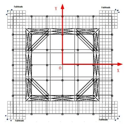
Fig.1 Platform coordinate system-top view

Fig.2 Platform coordinate system-side view
1.2 JCDDS/Mooring motion equation
Based on 3D potential theory[11],total velocity potential Φ can be derived as incident velocity potential,diffraction velocity potential and radiation velocity potential.Then,Lagrange’s integral is used to calculate the fluid force by pressure integration on the wet surface of the JCDDS,including wave exciting force,wave radiation force and restoring force.At the same time,JCDDS added mass and potential damping are obtained from radiation velocity potential.The corresponding added mass and potential damping are given as:

where φmrepresents the induced velocity potential when the floating body is oscillating in direction m with a unit speed.andmean respectively the added mass and the potential damping in direction m induced by the body oscillation in direction n.ω is the oscil-lation frequency,ρ is the density of the fluid,and S0is the wet surface of the floating body.
The computed frequency-domain hydrodynamic coefficients are used in time-domain equation expressed by a two-term Volterra series expression via a Kramers-Kronig relation[12].JCDDS motion equation in time domain is descripted[11,13-14]as:


In addition,the total external forcesin the right hand of Eq.(3)are given by wave excitation force,current-induced force and other external force(e.g.mooring force),respectively.
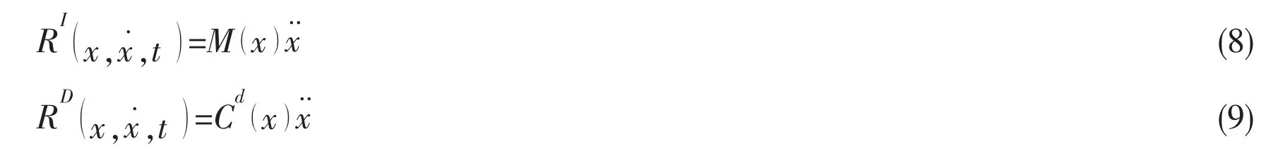
Generally,the dynamic equilibrium of a spatial discretized finite element system model is applied for the slender structure responses and expressed as[15]:

where RSis the internal structural reaction force vector,REis the external force vector including weight and buoyancy,forced displacements and specified forces,the inertia force vector and the damping force vector are respectively expressed as:
The numerical solution is based on step by step integration of the incremental dynamic equilibrium equations,with a Newton-Raphson type of equilibrium iteration at each time step.For numerical solution,the linearized incremental equation of motion is derived for the nonlinear incremental ones and can be expressed as:

A coupled method is applied in this paper by simultaneously solving JCDDS motion Eq.(3)and the slender structural motion Eq.(10)at each time step.
1.3 Morison equation
The Morison equation[10]assumes the inertia and drag forces could be linearly added together when the structure is small in size compared to the wavelength.And it is given as:

2 JCDDS dimensions and metocean conditions
A JCDDS with multi-point mooring system was investigated.The key dimensions are listed in Tab.1.A three-dimensional view of the hull is shown in Fig.3.
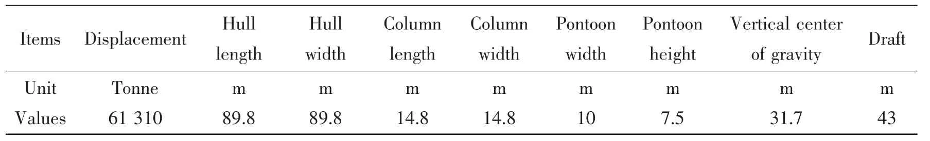
Tab.1 Main dimensions of the JCDDS

Fig.3 Three-dimensional view of the hull
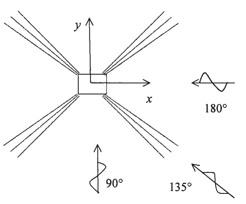
Fig.4 Spread mooring system
A 4×3 spreading mooring system is applied and shown in Fig.4,where incident angles of the environmental conditions are also defined.Tab.2 presents main parameters of the mooring lines.Each mooring line includes three segments with particular length,diameter,mass and axial stiffness EA.
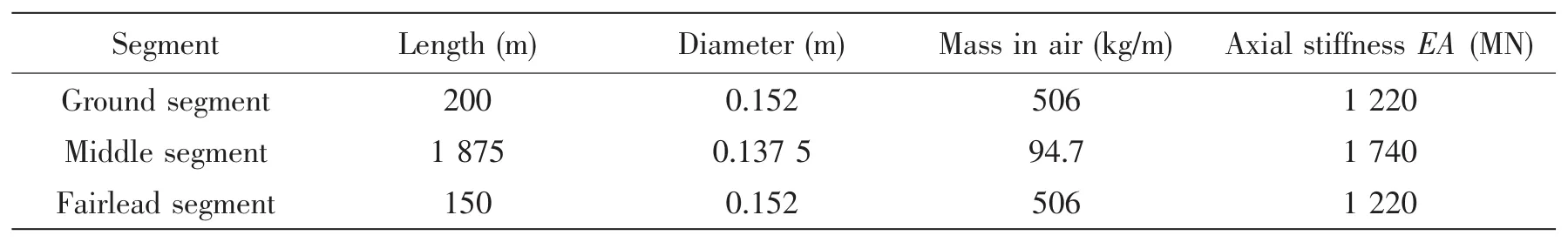
Tab.2 Parameters of the mooring lines
The waves are generated by JONSWAP spectra with different significant heights(Hs),directions and peak periods(Tp).The environmental combinations of the survival sea states and operational sea states are presented in Tab.3.Analysis in following is carried out basing on these sea states.
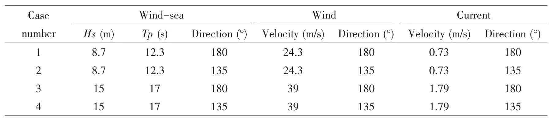
Tab.3 Metocean environmental combinations
3 Results and analysis
3.1 Wave spectrum
Model tests of the JCDDS were conducted in deepwater offshore basin,State Key Laboratory of Ocean Engineering,Shanghai Jiao Tong University.The deepwater offshore basin is 50 m×40 m,and the depth is 10 m,as well as a 5 m-diameter and 40 m-depth pit in the central is of the basin.The linear scale ratio is chosen as 60.The test cases include decay tests,RAO tests and the irregular wave tests for survival and fatigue conditions.All the models,environments and instruments are carefully calibrated.The calibrated and target wave spectrums are compared in Fig.5,which shows a good agreement.
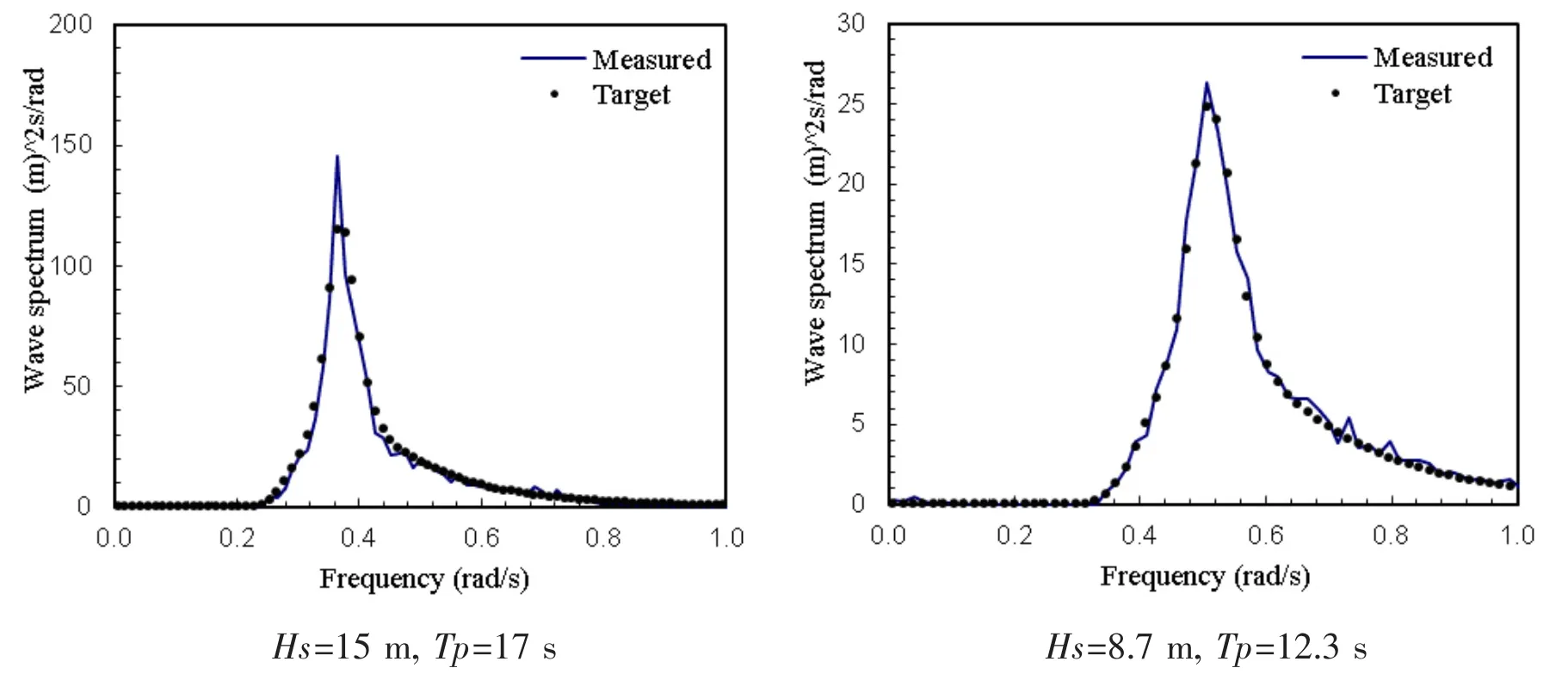
Fig.5 Target and measured wave spectrum
3.2 Verification of the response amplitude operators(RAOs)
The motion RAOs were calculated by the linear diffraction theory and derived by the white noise wave tests with wave periods ranging from 3 s to 25 s.Comparisons of the heave motion RAOs between the numerical and experimental results in the wave direction of 135°and of 180°are shown in Fig.6,respectively.At wave periods ranging from 3 s to 25 s,heave motion RAO is the main response comparing with other motion RAOs due to the different resonance period for different motions.Verifications of roll and pitch motion were achieved in the time-domain analysis.According to Fig.6,differences between the calculation and the model test at the main wave periods(i.e.from 7 s to 20 s)are small and small discrepancies are observed in the periods around the resonance peak.The comparisons indicate that results from the calculation are not identical comparing with those from the model tests,but it is acceptable considering the main wave periods ranges in different sea states.
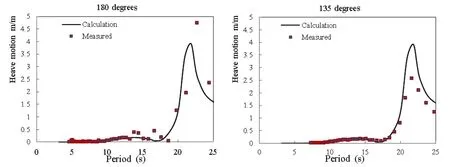
Fig.6 Comparisons of the heave motion RAO between numerical simulations and the model test
3.3 Verifications in the time-domain analysis
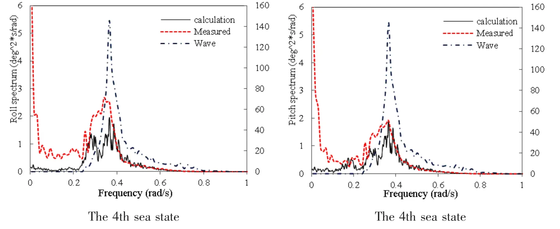
Comparisons between the numerical simulations and the model test were presented in the 2nd and 4th environmental combinations mentioned above.It should be noted that wave spec-trum is also presented in each figure as a contrast with the vertical axis presented in the right side.According to Fig.7,differences in heave,roll and pitch motions are small between the calculations and the model test,which is accurate to verify reasonableness of the numerical simulations.As this chapter is supposed to verify reasonableness of the numerical simulations,further analysis will be carried out in the following.
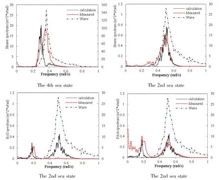
Fig.7 Spectra comparisons of different motions in the 2nd and 4th environmental combinations
3.4 Comparisons of the heave,roll and pitch motion RAOs of the traditional Semi and the JCDDS
Fig.8 and Fig.9 show comparisons of heave,roll and pitch motion RAOs between the traditional Semisubmersible platform(TSP)and the JCDDS with the same underwater structures in incident wave direction of 135°and of 180°,respectively.In the incident wave direction of 180°,roll motion RAO is small and thus not presented.According to Fig.8 and Fig.9,resonant periods of pitch and roll motion of the TSP are much smaller than those of the JCDDS.In addition,difference of the resonant periods of heave motion is small and cancellation period(marked in Fig.8)of the JCDDS is smaller than that of the TSP,while RAOs of the TSP at the wave frequency range(i.e.with the wave period ranging from 8 s to 17 s)are almost twice of the RAOs of the JCDDS.Differences between resonant periods of pitch and roll motion are mainly resulted from the disparate displacement as the two kinds of platform with similar un-derwater structure.Smaller heave RAOs of the JCDDS at the wave frequency range are mainly caused by the increase of the draft.The results indicate that the increase of the draft may result in decrease of the cancellation period and heave motion RAOs at the wave periods less than the cancellation period,which may contribute much to improvement of the heave response.
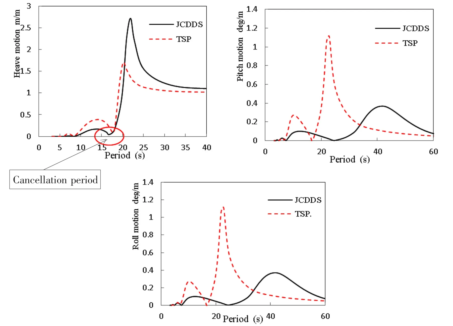
Fig.8 Motion RAOs in the incident wave direction of 135°
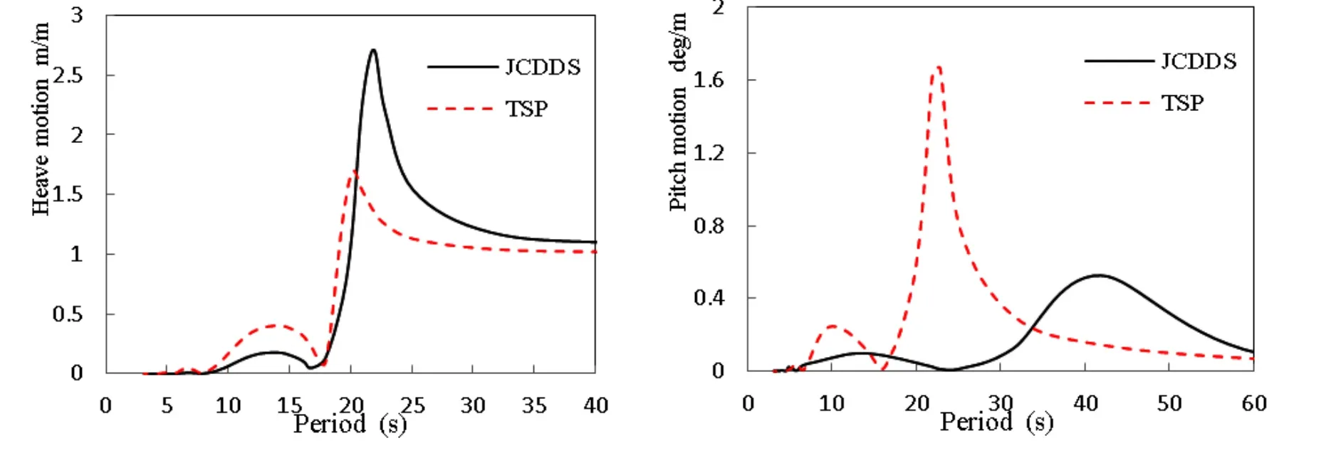
Fig.9 Motion RAOs in the incident wave direction of 180°
3.5 Jacket part effects on heave,roll and pitch motion RAOs of the JCDDS
Numerical simulations were carried out with and without the jacket part.Fig.10 and Fig.11 display comparisons of the motion RAOs in the incident wave direction of 135°and 180°,respectively.According to Fig.10 and Fig.11,differences of the heave,roll and pitch motion RAOs between the JCDDS with and without jacket part are minimal besides relatively obvious discrepancies at the resonant periods.According to the heave motion RAO,with the jacket part cancellation period is decreased a little and RAOs of heave motion are also decreased at periods less than the cancellation period and a little increased at periods larger than the resonant period.According to the pitch and roll motion RAOs,similar phenomenon could be observed.The results indicate that the jacket part could contribute positive effects on heave motion at wave periods ranging from 8 s to 17 s and on pitch and roll motion at wave periods ranging from 8 s to 25 s.The obvious discrepancies of motion RAOs are resulted from the fact that the wave period chosen for calculation near the natural period is much closer to the natural period of the JCDDS with jacket part than to that of JCDDS without the jacket part.With the jacket part,additional added mass and damping were considered and effects from this part are reasonable.
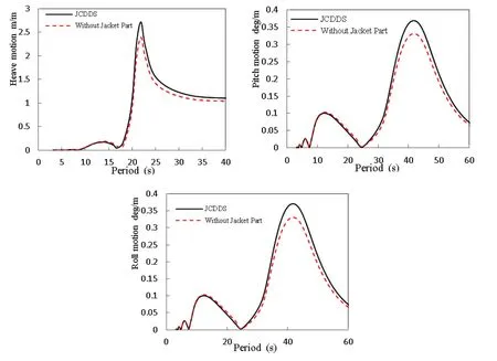
Fig.10 Comparisons of the motion RAOs in the incident wave direction of 135°
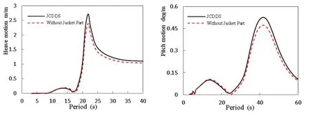
Fig.11 Comparisons of the motion RAOs in the incident wave direction of 180°
3.6 Jacket part effects on time-domain responses of heave,roll and pitch motion of the JCDDS
Comparisons between calculations with the jacket part and without were presented in the 100 year-return sea states in directions of 135°and 180°,respectively.Fig.12 presents comparisons of the statistics in the 3rd environmental combinations.The statistics of the roll motion are not presented because they are small and could be neglected in this case.Fig.13 presents comparisons of the statistics in the 4th environmental combinations.According to Fig.12 and Fig.13,though effects caused by the jacket part on the heave motion are larger than those on the roll and pitch motion,the differences between results with the jacket part and without are quite small;the absolute maximum motions were larger with the jacket part.The results indicate that additional forces caused by the jacket part may result in slightly increase of the motion responses.

Fig.12 Comparisons of the statistics in the 3rd environmental combinations
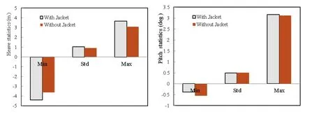
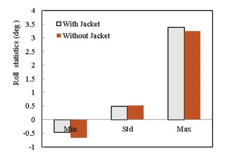
Fig.13 Comparisons of the statistics in the 4th environmental combinations
4 Conclusions
The following conclusions can be reached from the study conducted:
Results from the numerical simulations and the model test agree well,which verifies the numerical simulations.
Differences of the heave,roll and pitch motion RAOs are quite different between the TSP and JCDDS.Increasing the draft could greatly decrease heave motion RAOs at wave periods less than the cancellation period and could cause slight decrease of the cancellation period,which coincides with conclusions in references[4,16].
Slight differences were observed between results with the jacket and without both in the frequency-domain analysis and the time-domain analysis.In the frequency-domain,heave,roll and pitch motion RAOs at wave periods(for heave,ranging from 8 s to 17 s;for pitch and roll,ranging from 8 s to 25 s)are slightly decreased and are slightly increased at larger wave periods with the jacket part.It suggests that heave motion response could be further decreased by reasonably choosing dimensions of the jacket part as the heave motion is main focus especially for host platforms supporting the dry-tree well system.In the time-domain analysis,the absolute maximum motions of the heave,roll and pitch are slightly increased with the jacket because it causes additional wave force.
Acknowledgements
The work conducted here is part of the CNOOC research program of dry tree semis.The authors gratefully acknowledge the support of this work by CNOOC.
[1]Murray,John,Tahar,Acandra,Eilertsen,Terje.A comparative assessment of spar,tension leg platform and semisubmersible floaters for deepwater applications[C]//Deep Oil Conference.Houston Texas,2006.
[2]Cermelli C A,Roddier D G,Busso C C.A novel concept of minimal floating platform for marginal field development[C].14th International Offshore and Polar Engineering Conference,2004.
[3]Murray J,Chen C Y,Yang C K.Mating analysis of the truss and hull sections on the truss semisubmersible in open water[C].ASME 27th International Conference on Offshore Mechanics and Arctic Engineering,2008.
[4]Bindingshø A U,Bjøiset A.Deep draft semi-submersible[C].21st International Conference on Offshore Mechanics and Arctic Engineering,2002.
[5]Chen C Y,Ding Y,Mills T,et al.Improving the motions of a semi by the addition of heave plates[C].ASME 27th International Conference on Offshore Mechanics and Arctic Engineering,2008.
[6]Rijken O,Leverette S.Field measurements of vortex induced motions of a deep draft semisubmersible[C]//Proc.of the 28th International Conference on OMAE.Honolulu,HI,United States,2009,6:739-746.
[7]Prislin I,Blevins R D,Halkyard J.Viscous damping and added mass of solid square plates[C].17th International Conference on Offshore Mechanics and Arctic Engineering,1998.
[8]Chen C Y,Mei X M,Mills T.Effect of Heave plate on semisubmersible response[C].17th International Offshore and Polar Engineering Conference,2007.
[9]Thiagarajan K P,Datta I,Ran A Z,et al.Influence of heave plate geometry on the heave response of classic spars[C].21st International Conference on Offshore Mechanics and Arctic Engineering,2002.
[10]Morison J R,O’Brien M P,Johnson J W,Schaaf S A.The force exerted by surface waves on piles[J].Petroleum Transactions,AIME 18,1950:149-157.
[11]Dai Y S,Duan W Y.Potential flow theory of ship motions in waves[M].Beijing:National Defense Industry Press,2008.
[12]Koo B J,Kim M H.Hydrodynamic interactions and relative motions of two floating platforms with mooring lines in sideby-side offloading operation[J].Applied Ocean Research,2005:292-310.
[13]Cummins W E.The impulse response function and ship Motions[J].Schiffstechnik,1962,9:101-109.
[14]Marintek.Simulation of marine operations[M].Trondheim:Marintek,2009.
[15]Det Nørske Veritas.Deep water coupled floater motion analysis[R].Høvik:Det Norske Veritas,2005.
[16]Murray J,Tahar A,Yang C K.Hydrodynamics of dry tree semisubmersibles[C]//ISOPE-2007.Lisbon,Portugal,2007.

- 船舶力学的其它文章
- DES Simulation of Flow Field of Propeller Tip Vortex
- Numerical Study on the Hydrodynamic Behaviors of a Ship Passing Through a Lock in Shallow Water
- Characteristics of Tendon Vortex Induced Vibrations Influenced by Platform Motion
- Mechanical Behavior of Flexible Jumper Installation in 3D Space
- Load-Compression Relationship of Incompressible Circular Rubber Pad Bonded between Rigid Plates
- Two-dimensional Eulerian-Lagrangian Modeling of Shocks on an Electronic Package Embedded in a Projectile with Ultra-high Acceleration