
Determination of a suitable set of loss models for centrifugal compressor performance prediction
2017-11-17 08:31ElkinGUTIRREZVELSQUEZ
CHINESE JOURNAL OF AERONAUTICS 2017年5期
Elkin I.GUTIÉRREZ VELÁSQUEZ
Faculty of Mechanical Engineering,Universidad Antonio Nariño,Medellín 050012,Colombia
Determination of a suitable set of loss models for centrifugal compressor performance prediction
Elkin I.GUTIÉRREZ VELÁSQUEZ*
Faculty of Mechanical Engineering,Universidad Antonio Nariño,Medellín 050012,Colombia
Performance prediction in preliminary design stages of several turbomachinery components is a critical task in order to bring the design processes of the se devices to a successful conclusion.In this paper,a review and analysis of the major loss mechanisms and loss models,used to determine the efficiency of a single stage centrifugal compressor,and a subsequent examination to determine an appropriate loss correlation set for estimating the isentropic efficiency in preliminary design stages of centrifugal compressors,were developed.Several semi-empirical correlations,commonly used to predict the efficiency of centrifugal compressors,were implemented in FORTRAN code and the n were compared with experimental results in order to establish a loss correlation set to determine,with good approximation,the isentropic efficiency of single stage compressor.The aim of this study is to provide a suitable loss correlation set for determining the isentropic efficiency of a single stage centrifugal compressor,because,with a large amount of loss mechanisms and correlations available in the literature,it is difficult to ascertain how many and which correlations to employ for the correct prediction of the efficiency in the preliminary stage design of a centrifugal compressor.As a result of this study,a set of correlations composed by nine loss mechanisms for single stage centrifugal compressors,conformed by a rotor and a diffuser,are specified.
1.Introduction
Centrifugal compressors are an integral part of the industry due to the ir good performance,large tolerance to process fluctuations,and higher reliability compared to other compressors,and the y are,in many cases,considered as critical equipment in multiple processes.1Centrifugal compressors have different sizes depending on the ir pressure ratio,which can vary from 1:3 by stage to 12:1 in experimental models.2However,the ir performance calculation,for both design point and off-design conditions,requires the knowledge of the many phenomena which give rise to a series of losses that contribute to significant decrease of the ir efficiency.Therefore,the accurate calculation and proper weighting of the se losses are crucial to the design of centrifugal compressors because if certain design parameters are not properly controlled,the ir efficiency may decrease dramatically,which will generate a substantial increase in operating costs.
Correctly predicting the efficiency of a turbomachine is actually quite difficult.It demands a combination of the oretical and experimental results,from which a set of semiempirical correlations can be obtained.These semi-empirical correlations,dating from several decades,are ‘black boxes”that produce a relationship between inputs and outputs(without a physical description of the phenomenon),and are still the resource used to predict off-design characteristics of turbomachines,because available computational methods fail to predict the ir performance with sufficient accuracy.3
The aim of this paper is to establish a set of correlations that adequately predict the performance of centrifugal compressors in preliminary design stages,and since the wide variety of correlations and mechanisms available in the literature becomes problematic,itisa priority to know how many and which mechanisms should be used in order to properly predict the performance of centrifugal compressors.The present study conducts an analysis of different loss correlations reportedin the to determine the loss correlation set to determine the loss correlation set most suitablefor predicting the efficiency of single stage centrifugal compressors experimentallytested.Efficiency results of several experimental tests reported in the literature are compared with the computed isentropicefficiency obtained using the different loss correlation sets in order to determine the one that fits better with all of the centrifugal compressors analyzed in this study.
2.Centrifugal compressor losses
In some open literature sources,such as Refs.4,5,the losses are typically collected togethe r as a slip factor and/or loss coefficient.The disadvantage of this procedure is that the effects of the individual losses are not clearly characterized and the refore its influence is little recognized.On the other hand,some authors,such as Aungier6and Boyce,2document the individual losses in much greater detail.According to the m,the re are 11 well-documented loss mechanisms that affect the impeller,and the se loss mechanisms are:(A)shock;(B)incidence;(C)diffusion;(D)choke;(E)skin friction;(F)clearance gap;(G)blade loading;(H)hub-shroud loading;(I)wake mixing;(J)expansion;(K)supercritical Mach number.
However,the losses with the highest impact on the performance of the compressor according to Aungier6are:(A)skin friction loss;(B)entrance diffusion loss;(C)recirculation;(D)incidence loss;(E)clearance loss;(F)disk friction loss.
Besides losses on the impeller,energy losses must likewise be evaluated in both the vaneless diffuser and vaned diffuser.In the vaneless diffuser,the losses are due to skin friction and diffusion.6The vaned diffuser exhibits energy losses associated with skin friction,incidence angle,blockage,wake mixing,and choking.
However,some of the correlations available in the literature,obtained experimentally,for different loss mechanisms,take into consideration several mechanisms of loss simultaneously due to the extreme difficulty of differentiating its effects,eithe r for technical or conceptual issues,so the use of correlations for all loss mechanisms would lead to an overestimation of the overall loss of the compressor.
Consequently,the selection of a set of correlations for calculating loss of efficiency in turbomachines is not a trivial task,so it requires proper selection of mechanisms and correlations to be considered for the correct prediction of the overall efficiency.Below is presented a study aimed at evaluating the losses obtained using different loss correlations to establish a combination of models to predict the efficiency of various centrifugal compressors using an appropriate set of correlations.
3.Loss models
In this analysis,nine loss mechanisms will be considered.Three models will be used for evaluating clearance loss,four models for disk friction loss,two loss models for recirculation loss,two models for leakage loss,and one model for:skin friction loss,incidence loss,blade loading loss,vaneless diffuser loss and vaned diffuser loss.The different mechanisms and models are evaluated as described below.
3.1.Clearance loss
Clearance loss considers the flow escaping from impelling by the clearance between the blades and the outer casing of the compressor,from the pressure side to the suction side.In this work,the estimation of clearance loss is computed using the loss correlations proposed by Rodgers,7Krylov and Spunde,8Jansen,9and the se correlations are shown in Eqs.(1)–(3)respectively.

where ΔHclis the clearance loss,s is the clearance gap,b is the blade height,r is the radius,U is the circumferential speed,V is the absolute velocity at inlet,Vuis the circumferential component of the absolute velocity,ρ is the density of the fluid in the inlet and discharge of the impeller,Ziis the number ofimpeller blades,and the subscripts ‘h”and ‘s” refer to the impeller inlet hub and shroud respectively, ‘1”refers to the impeller inlet and ‘2” refers to the impeller discharge.
3.2.Disk friction loss
This loss mechanism occurs as a result of adhesiveforces between the rotating disk and the fluid in the surrounding enclosure.The induced flows depend on the geometries of the impeller and its enclosure.10The disk friction loss models evaluated in this work are shown in Eqs.(4)–(7)and were introduced by Aungier,6Daily and Nece,11Shepherd12and Boyce2respectively.
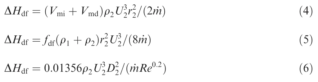
where ΔHdfis the disk friction loss,Vmiand Vmdare the absolute meridional velocities in the impeller and the diffuser respectively,Re is the Reynolds number,fdfis a disk friction factor defined as fdf=2.67/(Redf)0.5that if the flow is turbulent (Redf<3 × 10⁵)or fdf=0.0622/(Redf)0.2if the flow is laminar (Redf≥ 3×10⁵)with Redf=U2r2/ν2,ν is the kinematic viscosity,Qthis the the oretical non-dimensional head,˙m is the mass flow rate,p is the pressure,D is the diameter of the impeller.
3.3.Recirculation loss
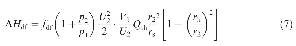
This loss is associated with recirculation of air from the diffuser to the impeller,13and this recirculation is caused by the increased flow angle at the exit,which makes part of the energy given to the fluid return to the impeller.2The loss models evaluated in this work were given by Coppage et al.14and Oh et al.3are presented in Eqs.(8)and(9)respectively.
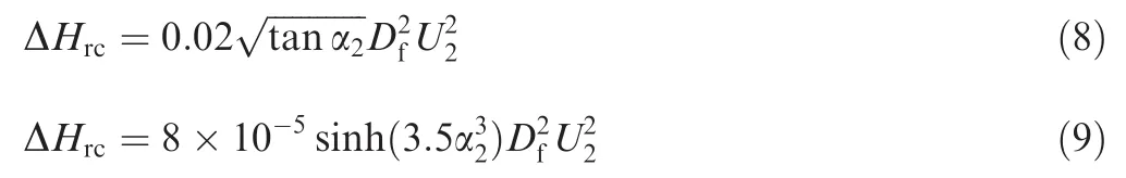
where ΔHrcisthe recirculation loss,α is flow angle,is the diffusion factor,W is the tangential component of relative velocity,and ΔHaerois the aerodynamic enthalpy that is obtained by Eq.(10).
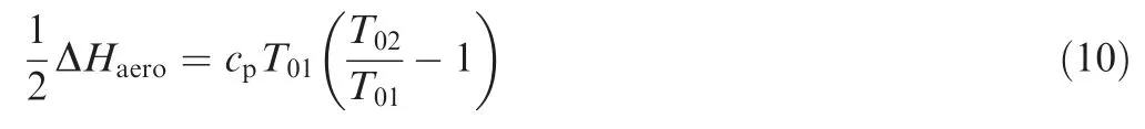
where T01and T02are the inlet and discharge total temperature of the compressor,and cpis the specific heat at constant pressure.
3.4.Leakage loss
This loss is caused by leakage offluid through the compressor seals to regions of low pressure.In this paper,the se losses are estimated by loss correlations proposed by Aungier6and Jansen9as shown in Eqs.(11)and(12)respectively.

where ΔHlkis the leakage loss, ε is the clearance gap,and the subscript ‘m” refers to meridional direction.
3.5.Incidence loss
This loss mechanism considers flow adjustment offluid to the inlet angle of the blade of the impeller,and the fluid in close proximity to the blade instantly experiences a speed change to follow the inlet angle of the blade.When the fluid separation occurs,losses are generated associated with this phenomenon.2Incidence loss is evaluated by the correlation proposed by Conrad et al.15,which is presented in Eq.(13).

where ΔHincis the incidence loss,fincis a incidencefactor,which can take values between 0.5 and 0.7,and Wuiis the tangential component ofimpeller inlet relative velocity.
3.6.Blade loading loss
This loss is developed due to the negative gradient of velocity in the boundary layers,and such deceleration increases the thickness of the boundary layer,leading to flow separation which may lead to a stall event.This loss is computed by Eq.(14)given by Coppage et al.14

where ΔHblis the blade loading loss.
3.7.Skin friction loss
This loss results from the action of shearing forces on the walls of the impeller due to the turbulent fluid friction.This loss is calculated by considering the flow over a circular section(based on the equivalent hydraulic diameter approach),and its calculation is based on the equations for loss calculation in pipes.The skin friction loss is evaluated by Eq.(15)agreeing to Jansen.9

where ΔHsfis the skin friction loss,Cfis the skin friction coefficient,Lbis the impeller flow length and Dhydis the impeller average hydraulic diameter.
3.8.Vaneless diffuser loss
This loss is experienced in the vaneless diffuser space as a result offriction and the absoluteflow angle.Vaneless diffuser loss is assessed by the correlation proposed by Stanitz,16shown in Eq.(16).
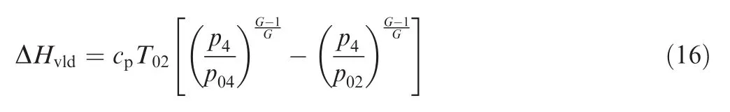
where ΔHvldis the vaneless diffuser loss,T is the temperature,G is the ratio of specific heats and the subscripts ‘0” and ‘4”refer to total condition and inlet of the vaned diffuser respectively.
3.9.Vaned diffuser loss
These losses arefound in experimental results performed in conical diffusers,and are a function of load on the blades and the space of the vaneless diffuser;the incidence angle and the surfacefriction of the vanes are also considered.This loss is also estimated by the correlation proposed by Stanitz16as shown in Eq.(17).
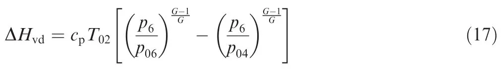
where ΔHvdis the vaned diffuser loss and the subscript ‘6”refers to the discharge of the vaned diffuser.
4.Overall isentropic efficiency calculation
The efficiency decrements induced by the individual losses are obtained from Eq.(18):
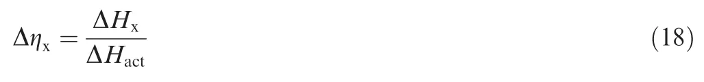
where Δηxand ΔHxare the individual decrement in efficiency and the individual enthalpy loss,respectively,associated to each mechanism assessed,and the actual enthalpy ΔHactis defined in Eq.(19)

where the parasitic head enthalpy ΔHparis calculated by Eq.(20):

Then the compressor’s overall isentropic efficiency is computed by Eq.(21):

where the internal head enthalpy ΔHintis defined in Eq.(22)

5.Assessment results
In this analysis,the loss correlations presented in Eqs.(12)–(16)were combined with the three loss correlations for estimating clearance loss,four loss correlations for disk friction loss,two loss correlations for recirculation loss,and two loss correlations for leakage loss.Consequently,48 sets of loss correlations were obtained as listed in Table 1.
The 48 loss correlation sets were evaluated in five different centrifugal compressor stages,whose configurations and efficiencies,obtained from the Refs.17–21,are detailed in Table 2.These centrifugal compressor stages have pressure ratios(PR)among 2 and 8,mass flow rates(˙m)between 0.35 kg/s and 4.55 kg/s,and rotational speeds(N)in a range between 20000 r/min and 80000 r/min.In addition,in Table 2,η is the isentropic efficiency of the stage,β2iis the blade angle at impeller discharge,D6/D5is the diffuser diameter ratio,and the subscripts ‘5” and ‘6” refer to inlet and discharge of the vaned diffuser respectively.In Fig.1,the main parameters(normalized)of the different centrifugal compressors evaluated in this work are presented.
From the loss correlation sets listed in Table 1 and the centrifugal compressor configurations shown in Table 2,the isentropic efficiencies were determined for each loss correlation set and for each centrifugal compressor stage using FORTRAN code,developed and validated by GutiÉrrez VelÁsquez et al.,22which allows to estimate the isentropic efficiency for eachconfiguration.The stage efficiency results for each loss correlation set and for each compressor stage were calculated,and are shown in Table 3 and presented graphically in Fig.2,in which the radial axis represents the compressor stage isentropic efficiency and the spokes represent the different loss correlation sets tested.

Table 1 Correlation sets assessed.

Table 2 Centrifugal compressors assessed.

Fig.1 Normalized parameters comparison.

Table 3 Isentropic efficiencies for each set and compressor assessed.
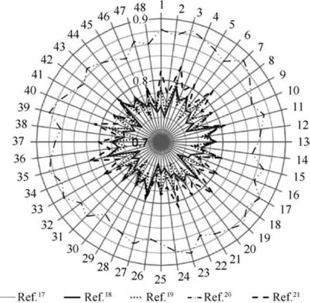
Fig.2 Isentropic efficiency results for each loss correlation set assessed.
From furthe r analysis,aimed to determine the composition of the best set of losses that can be predicted,with suitable accuracy,the efficiency for all compressors considered in this analysis leads to the set of semi-empirical correlations more appropriately corresponding to the set identified with the number 29 in Table 1 and underlined in Table 3,which corresponds with the set of correlations for recirculation loss,leakage loss,clearances loss,skin friction loss,disc friction loss,blade loading,incidence loss,vaneless diffuser loss and vaned diffuser loss proposed by Oh et al.,3Aungier,6Krylov and Spunde,8Jansen,9Shepherd,12Coppage et al.,14Conrad et al.15and the latter two by Stanitz16respectively.
According to the above,the deviations between the efficiencies obtained numerically and those reported experimentally,for the centrifugal compressors evaluated with the correlation set number 29,are in all cases less than 1%,as shown in Table 4 which shows the experimental efficiencies(ηexp)reported in Refs.17–21versus the calculated isentropic efficiencies(ηs,cal),and the ir respective differences.
According to the results presented in Table 3,when considering the different loss correlation sets,differences of up to 8%can be obtained on the stage isentropic efficiency,so that the selection of an appropriate loss correlation set is critical to predicting the compressor stage efficiency with good accuracy.
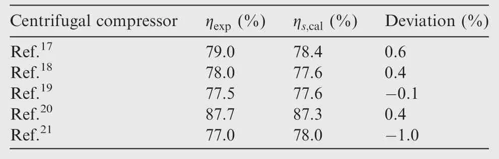
Table 4 Results of efficiency comparison.

Fig.3 Discrimination of centrifugal compressor losses.
From the above results,the discrimination of calculated centrifugal compressor losses in:internal losses(ΔHint),parasitic losses(ΔHpar)and diffuser losses(ΔHdif)was performed and is shown in Fig.3.It can be seen that the internal losses are the most important in this type of compressors;however,for centrifugal compressors reported by Danish17and Krain et al.,18the se losses amount to around 60%and 70%respectively,with respect to total losses,suggesting where efforts should be directed to primarily to carry out furthe r optimization processes.In the case of the centrifugal compressor presented by Galvas,19although internal losses do not represent such a high percentage,the diffuser system reaches a value higher than 25%,respect to total losses,which makes this compressor have a reduced efficiency.
On the other hand,when the centrifugal compressors exhibit high pressure ratios,one model to estimate the shock losses should be used in order to obtain a more realistic efficiency.This can be the reason why the centrifugal compressors described by Galvas19and Osborne et al.21exhibit higher calculated efficiencies than the experimental efficiencies.This suggests that when the compressor ratio is high,a shock loss model should be considered for better estimations.
6.Conclusions
(1)This paper reviews the principal loss mechanisms occurring in centrifugal compressors,as well as some of the loss correlations developed to evaluate the se mechanisms.
(2)Given the wide variety of loss mechanisms and models available in the literature,an analysis aimed at establishing an appropriate set of the se loss models,which is crucial for the proper assessment of centrifugal compressor efficiency,was developed.
(3)In this work,five centrifugal compressors,whose settings and efficiencies,experimentally determined,are reported in the literature were evaluated by a computer code to establish a set of loss models that allows properly predicting the stage efficiency of this type of turbomachines.
(4)This study was focused on proposing a usual systematic set of correlating losses in centrifugal compressors;however,for particular cases,additional models should be incorporated in order to consider particular features.
(5)From this study,it can be concluded that application of an inappropriate set of correlations may result in loss of efficiency predictions that can get away with values up to 8%in the centrifugal compressor stage isentropic efficiency,which constitutes a big mistake to be adopted in the preliminary stages of design of the se compressors.
Acknowledgment
The author would like to thank all the faculty members of Universidad Antonio Nariño for the ir critical advice and guidance.They are a wonderful team of contributors.
1.Forsthoffer WE.Forsthoffer’s bestpractice handbook for rotating machinery.Oxford:Butterworth-Heinemann;2011.p.93–228.
2.Boyce MP.Centrifugal compressors:A basic guide.Tulsa:Pennwell Books;2003.
3.Oh HW,Yoon ES,Chung MK.An optimum set of loss models for performance prediction of centrifugal compressors.Proceed Inst Mech Eng,Part A:J Power Energy 1997;221(4):331–8.
4.Watson N,Janota MS.Turbocharging the internal combustion engine.London:The Macmillan Press Ltd.;1982.
5.Japikse D.Centrifugal compressor design and performance.White River Junction:Concepts Eti;1996.
6.Aungier RH.Centrifugal compressors:A strategy for aerodynamic design and analysis.New York:ASME;2000.
7.Rodgers C.Paper 5:A cycle analysis techniquefor small gas turbines.Proceedings of the Institution of Mechanical Engineers,Conference Proceedings 1968;183(14):37–49.
8.Krylov EP,Spunde EA.About the influence of the clearance between the working blades and housing of a radial turbine on its exponent.1967.Report No.:FTD-MT-67-15.
9.Jansen W.A method for calculating the flow in a centrifugal impeller when entropy gradients are present.Royal society conference on internal aerodynamics(turbomachinery);1970.
10.Botha BW,Moolman A.Determining the impact of the different losses on centrifugal compressor design.Res Develop J 2005;21(3):23–31.
11.Daily JW,Nece RE.Chamber dimension effects on induced flow and frictional resistance of enclosed rotating disks.J Basic Eng 1960;82(1):217–30.
12.Shepherd DG.Principles of turbomachinery.London:Macmillanc Pub Co.;1956.
13.Galvas MR.Analytical correlation of centrifugal compressor design geometry for maximum efficiency with specific speed.Washington,D.C.:NASA;1972.Report No.:NASA-TN-D-6729.
14.Coppage JE,Dallenbach F,Eichenberger JP,Hlavaka GE,Knoernschild EM,Vanke N.Study of supersonic radial compressors for refrigeration and pressurization systems.Inform Process Lett 1956;1(4):157–63.
15.Conrad O,Raif K,Wessels M.The calculation of performance maps for centrifugal compressors with vane-island diffusers.Proceedings of the twenty-fifth annual international gas turbine conference and exhibit and twenty-second annual fluids engineering conference;1980 Mar 9–13;New Orleans,USA.New York:ASME;1979.p.135–47.
16.Stanitz JD. One-dimensional compressibleflow in vaneless diffusers of radial-and mixed-flow centrifugal compressors,including effects offriction,heat transfer and area change.Boston:NACA;1952.Report No.:NACA-TN-2610.
17.Danish SN,Ma CC,Yang C.The influence of tip clearance on centrifugal compressor stage of a turbocharger.Proceedings of the 4th WSEAS international conference on fluid mechanics and aerodynamics;2006 Aug 21–23;Elounda,Greece.2006.p.6–11.
18.Krain H,Hah C.Numerical and experimental investigation of the unsteady flow field in a transonic centrifugal compressor.Proceedings of the international gas turbine congress;2003 Nov 2–7;Tokyo,Japan.2003.p.6–11.
19.Galvas MR.A compressor designed for the energy research and development agency automotive gas turbine program.Washington D.C.:NASA;1975.Report No.:NASA-TM-X-71719.
20.Larosiliere LM,Skoch GJ,Prahst PS.Aerodynamic synthe sis of a centrifugal impeller using CFD and measurements.Reston:AIAA;1997.Report No.:AIAA-1997-2878.
21.Osborne C,Runstadler PW,Stacy WD.Aerodynamic and mechanical design of an 8:1 pressure ratio centrifugal compressor.Washington,D.C.:NASA;1974.Report No.:NASA-CR-134782.
22.GutiÉrrez VelÁsquez EI,Nascimento MR,Miranda RAC,Moura NR.One and three-dimensional analysis of centrifugal compressor for 600 kW simple cycle gas turbine engine.New York:ASME;2010.Report No.:GT2010-22950.
16 February 2016;revised 19 April 2016;accepted 9 May 2016
Available online 22 August 2017
Centrifugal compressor;
Efficiency loss;
Performance prediction;
Preliminary design;
Turbomachinery
*Corresponding author.
E-mail address:elkin.gutierrez@uan.edu.co.
Peer review under responsibility of Editorial Committee of CJA.
Production and hosting by Elsevier
http://dx.doi.org/10.1016/j.cja.2017.08.002
1000-9361©2017 Production and hosting by Elsevier Ltd.on behalf of Chinese Society of Aeronautics and Astronautics.This is an open access article under the CC BY-NC-ND license(http://creativecommons.org/licenses/by-nc-nd/4.0/).
©2017 Production and hosting by Elsevier Ltd.on behalf of Chinese Society of Aeronautics and Astronautics.This is an open access article under the CC BY-NC-ND license(http://creativecommons.org/licenses/by-nc-nd/4.0/).
 CHINESE JOURNAL OF AERONAUTICS2017年5期
- CHINESE JOURNAL OF AERONAUTICS的其它文章
- Effect of an end plate on surface pressure distributions of two swept wings
- Blade bowing eff ects on radial equilibrium ofinlet flow in axial compressor cascades
- A model offlow separation controlled by dielectric barrier discharge
- Research on parafoil stability using a rapid estimate model
- Transonic buff et control research with two types of shock control bump based on RAE2822 airfoil
- Tomography system for measurement of gas properties in combustion flow field