
Blade bowing eff ects on radial equilibrium ofinlet flow in axial compressor cascades
2017-11-17 08:31HnXUHoCHANGDonghiJINXingminGUI
CHINESE JOURNAL OF AERONAUTICS 2017年5期
Hn XU,Ho CHANG,Donghi JIN,*,Xingmin GUI
aSchool of Energy and Power Engineering,Beihang University,Beijing 100083,China
bAECC Shenyang Engine Research Institute,Shenyang 110015,China
Blade bowing eff ects on radial equilibrium ofinlet flow in axial compressor cascades
Han XUa,Hao CHANGb,Donghai JINa,*,Xingmin GUIa
aSchool of Energy and Power Engineering,Beihang University,Beijing 100083,China
bAECC Shenyang Engine Research Institute,Shenyang 110015,China
The circumferentially averaged equation of the inlet flow radial equilibrium in axial compressor was deduced.It indicates that the blade inlet radial pressure gradient is closely related to the radial component of the circumferential fluctuation(CF)source item.Several simplified cascades with/without aerodynamic loading were numerically studied to investigate the effects of blade bowing on the inlet flow radial equilibrium.A data reduction program was conducted to obtain the CF sourcefrom three-dimensional(3D)simulation results.Flow parameters at the passage inlet werefocused on and each term in the radial equilibrium equation was discussed quantitatively.Results indicate that the inviscid bladeforce is the inducement of the inlet CF due to geometrical asymmetry.Blade bowing induces variation of the inlet CF,thus changes the radial pressure gradient and leads to flow migration before leading edge(LE)in the cascades.Positive bowing drives the inlet flow to migratefrom end walls to mid-span and negative bowing turns it to the reverse direction to build a new equilibrium.In addition,comparative studies indicate that the inlet Mach number and blade loading can efficiently impact the effectiveness of blade bowing on radial equilibrium in compressor design.
1.Introduction
To control the secondary flows in turbine machines,the concept of blade bowing was published in the 1960s by Deich et al.1Since the n,experimental and numerical investigations of bowed blades were carried out in both compressors and turbines.2–11Blade bowing has been proved to be an effective design method to control corner separation and reduce secondary flow loss in design.
The experimental studies of Breugelmans2and Shang3et al.showed that blade bowing and lean strongly influenced the development of the secondary flows in rectilinear compressor cascades.For bowed blade,the corner stall was reduced at both suction/end-wall surface corners,whileflow losses were increased at the mid-span.Weingold et al.4showed that bowed stator generated radial forces on the flow within the blade passage,which reduced the diffusion rate in the suction surface corner,and substantially delayed or eliminated the formation of corner separation.Fischer et al.5studied the effects of strongly bowed stator vanes on the performance of a fourstage high-speed compressor.Results showed that the bowed stators eliminated the corner stall at hub and leaded to the increase of overall static pressure rise,total pressure rise,and overall efficiency,when the compressor was highly loaded.Chen et al.11proposed a partial bowed rotor bladefor a newly designed high loaded axial fan.Numerical studies presented that the separated flow was reduced,the efficiency of the fan with bowed blades was enhanced by 1.44%,and the static pressure rise was increased by 11%under design condition.
As mentioned above,most of the former studies focused on the improvements of the corner flow and total performance achieved by using bowed blades while the inlet flow variation was neglected.Although the change of the stacking line in bowed blades may lead to complicated interaction of different flow parameters,the inlet flow condition is believed to be the key factor as the element pro file remains the same.However,in recent years,some researchers have noticed the inlet flow migration induced by sweep and blade bowing.The experimental results of McNulty et al.12showed that more flows were pulled towards the blade tip in forward swept rotors where higher inlet axial velocity was discovered.As a result,the leakage flow blockage and the aerodynamic loading were reduced in the tip region.Gallimore et al.13presented the computational fluid dynamics(CFD)results of a single stage axial compressor,which indicated that both the velocity pro file and the incidence angle changednear the leading edge(LE)with the application of sweep and dihedral.The numerical study of Ramakrishna and Govardhan14clearly reported that lower incidences were received in a subsonic axial compressor as the blades wereforward swept,leading to the mass flow rate variations.However,the authors considered the stagger angle as the keyfactor of this phenomenon.Gabriele et al.15described the pressure distribution upstream the blade passage in a straight cascade with the lean angle of 20°.Hefound that the pressure levels at two end walls were quite different when the blade was positively leaned.A radial pressure gradient upstream the LE was observed and thrust the flows from hub to tip.Tan et al.6–8studied the effects of blade bowing on the aerodynamic performance of highly loaded turbine cascades and showed that the incidence angles were different in the cascades with different bow angles,but the mechanism of the inlet flow change was not described.
Through the designing of multistage compressors with the application of bowed and swept blades,it is very common to have blade loading variation along the span,which results in the different requirements of the incidence characteristic.So the question worth researching is how blade bowing and sweep induce the inlet flow variety and how to use this effectiveness to obtain the maximum benefits of the aerodynamic performance.On account of the complicacy of 3D flows,dimensionality reduction is preferred by some researchers as an effective approach to understand the mechanism of blade bowing and sweep quantitatively.
Based on this idea,Gui et al.16firstly discovered the relevance between the inlet flow migration and the circumferential fluctuation(CF)in axial fans/compressors with sweep using circumferentially averaged method.He attributed the incidence angle change and the sweep characteristics to the new radial equilibrium established by the inlet CF in the subsonic compressors/fans.The previous works of Chang et al.17proved the effects of the inlet CF on the inlet flow migration in different swept cascades.The study indicated that blade sweep did affect the inlet radial equilibrium and the inlet flow field varied mainly due to the combined effects of the radial pressure gradient and the CF source components.
As another three-dimensional blading concept,blade bowing is convinced to have significant in fluence on the blade inlet flow like sweep does in axial compressors,and the inlet CF should play an important role in the rebuilding of the inlet radial equilibrium.This paper presents a numerical study of simplified cascades to investigate the mechanism of the inlet equilibrium variation in bowed cascades.The circumferentially averaged method introduced in Ref.16 is also used here to obtain the inlet CF source.
2.Blade inlet circumferential fluctuation
Lots offactors may contribute to the inlet CF in compressors,such as the inlet distortion and the wake interferencefrom upstream.But for a single blade row with uniform incoming flow,the inlet CF can be considered as the extending of the CF within the blade passage.The circumferential pressure fluctuation acts on the flow as inviscid bladeforce inside the blade passage.The inviscid bladeforce turns to zero before the LE,but the pressure fluctuation remains nonzero.Fig.1 presents the pressure distribution of a single blade row and it can be noticed that the inlet flow is circumferentially nonuniform.So the inlet CF is an inherent characteristic of the geometrically asymmetric blade rows,and it can be represented by the CF source items obtained with the circumferentially averaged method.
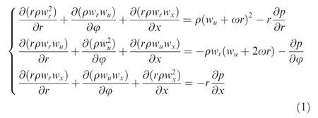
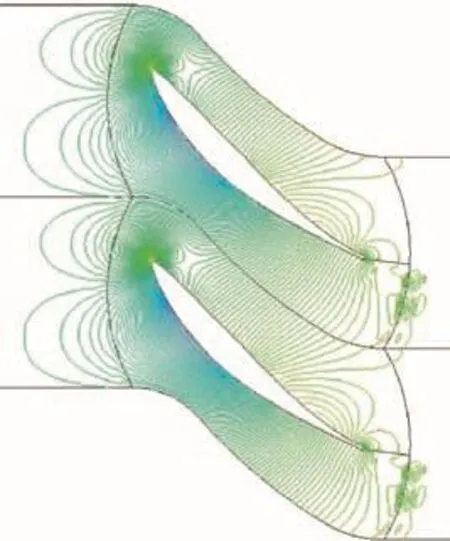
Fig.1 Pressure distribution of single blade row.
For inviscid flow in rotational cylindrical coordinates,the radial,circumferential and axial components of the Navier-Stokes momentum equations are expressed as follows,eliminating volumeforce:where r,φ and x are the radial,circumferential and axial coordinates in cylindrical coordinates,respectively;w represents the relative velocity,ω the angular speed,ρ the density,and p the static pressure.The subscript r,u,and x represent the radial,circumferential and axial directions,respectively.
Eq.(1)can be circumferentially averaged through passage and density to obtain the control equations of the circumferentially averaged method for inviscid flow:

with the components of the inviscid bladeforce FB:

and the components of the CF source items P:
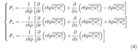
In Eq.(1),parameters such as stress,pressure and force are passage-averaged while the velocity is density-averaged.The superscript overline represents passage average while the dual-overline represents density weighted average.Similarly,the′and′represent the CF based on passage average and density weighted average,respectively.And b is a blockagefactor with the form

where φs- φpis the circumferential bade thickness,and the subscript s and p represent suction and pressure side respectively;N is the number of blades.The blockagefactor b is lower than 1.0 inside the blade passage and equal to 1.0 outside it.
The radial component of Eq.(2)can be substituted by the following one:
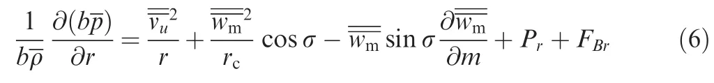
Eq.(6)is the circumferentially averaged equation of the radial equilibrium.The subscript m represents the stream direction in meridian plane,σ the angle between the stream surface and the axial direction,rcthe local curvature radius of the streamline,v the absolute velocity,and m the streamwise coordinate.Thefirst item of Eq.(6)expresses the radial pressure gradient;the second one represents the centrifugal force generated by the circumferential velocity;the third one is the radial component of the centrifugal forcefrom the velocity in the stream curvature direction;the fourth one represents the radial component of the forcefrom the stream acceleration in the meridional plane.In this paper,the y are named as GPRand DMRrespectively.
As shown in Eq.(3),the inviscid bladeforce equals zero before the LE,while the CF sources remain nonzero and have effects on the inlet flow according to Ref.16.The circumferential component Puchanges the average circulation along the meridianal streamline direction,and Pxand Praffect the pressure distribution in axial and radial directions,respectively.When blade is bowed,the inlet CF sources change and lead to the variation of the inlet pressure distribution,and thus the inlet flow migrates in the new pressure gradient and establishes a new equilibrium.
3.Numerical model
3.1.Cascade model
To investigate the effects of blade bowing on the inlet radial equilibrium,a series of simplified cascades were analyzed with numerical simulation and circumferentially averaged results.Cascades without aerodynamic loading were studied firstly to explore the inducement of the inlet CF.Then cascades with uniform aerodynamic loading but different bow angles were investigated,which is followed with the comparison of the effects of design parameters including camber angle and inlet Mach number.For all the cascades,the mean camber line of the element profile is circular arc.The thickness distribution is the same as the MAN GHH 1-S1 controlled diffusion airfoil.18The basic parameters of the cascades are listed in Table 1.In order to investigate the blade bowing mechanism independently,an aspect ratio of 6.0 was selected to minimize the effects of the end wall boundary layer in the mid-span region.
3.2.Blade bowing definition
In this paper,blade bowing is induced by moving the airfoil in the blade-blade direction with the stacking line of circular arc,as shown in Fig.2,SS and PS represent suction surface and pressure surface.The bow angle is defined as the angle between the stacking line and the radial direction at end walls.The blade bowing is called positive when the dihedral angle between the blade pressure side and the end wall is acuteand vice versa.8Both positive and negative bowed cascades were modeled and compared with the straight one.For comparative purpose,ST,PB and NB represent straight,positively bowed and negatively bowed,respectively,in this paper.
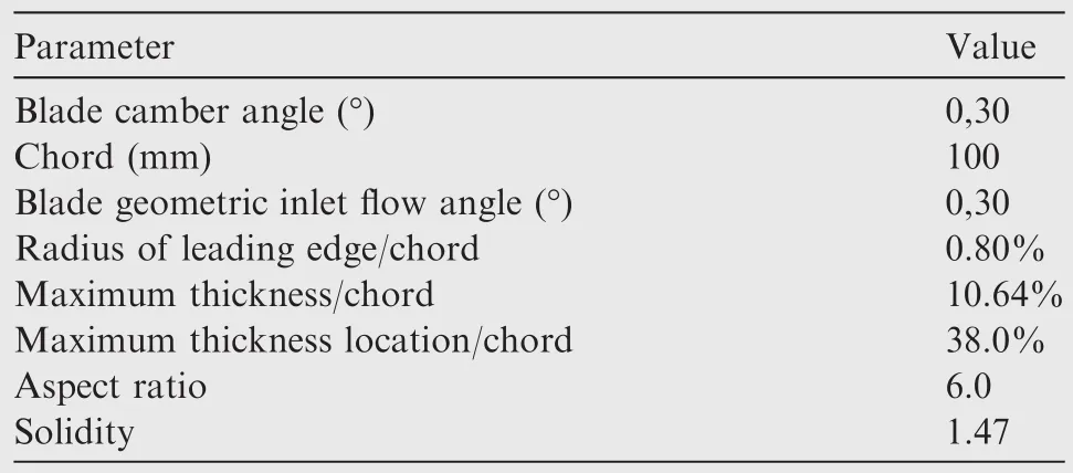
Table 1 Basic parameters of cascade.

Fig.2 Stacking line of bowed blade and blade profile.
3.3.Numerical method
The 3D numerical computations were carried out by the Navier-Stokes solver FINE Turbo made by NUMECA International based on the finite volume method.Each cascade was meshed with 1376000 cells as shown in Fig.3 in the AUTOGRID module of NUMECA software.Both the inlet and outlet blocks were configurated with the H-type grid,and the blade passage block was meshed with the O-type grid.The mesh topological structures of all the compared cascades are identical.Total temperature and total pressure were imposed with the values of 101325 Pa and 288.15 K respectively at the blade inlet.The inlet flow angle was set equal to the inlet metal angle of the cascade to ensure that the nominal incidence was zero.Quality mass flow rate was imposed at the outlet to control the inlet velocity.To lessen the effects of inlet boundary layer,the inlet Mach number was set to 0.15.Adiabatic nonslipping condition was applied at the cascades’surfaces and end walls.The Spalart-Allmaras model was adopted as the turbulence model for its excellent behavior of prediction precision and numerical stability.

Fig.3 Grids of 3D computational domains.

Fig.4 Grids of circumferentially averaged method.
The 3D flow field data were extracted from the numerical computation results.Then the 3D parameters were circumferentially averaged to obtain the CF sources using in-house codes.The circumferentially averaged Navier-Stokes equations were solved using time-marching finite volume method.The convectivefluxes were discretized with the Edwards’lowdiffusion flux-splitting schemes(LDFSS).19The viscous fluxes were calculated requiring the evaluation of the primitive variables and the first derivatives of the m at the middle of the cell edge.An explicit Runge-Kutta method was employed for the time discretization as it is straightforward to implement.The 2D meshes were created using bilinear interpolation method and the grid was densified near the LE,as shown in Fig.4.The details of the circumferentially averaged method can befound in Ref.20.
4.Results and discussion
The inlet flow CF and the radial equilibrium parameters were compared in cascades with/without aerodynamic loading firstly.Then the effects of design parameters such as the camber angle and stagger angle were studied independently.All comparisons were conducted under the same uniform inlet boundary condition at the unique axial position with the distance of 1.5%chord length before the blade LE.
4.1.Cascades without aerodynamic loading
A series of simplified cascades without aerodynamic loading(0°blade camber angle)were investigated firstly.The cascades were positively and negatively bowed with the bow angle of 20°.One group had the inlet flow angle of 0°and the other group had that of 30°.Fig.5 presents the blade-blade pressure distribution of two groups with the inlet flow angles of 0°and 30°respectively.With inlet flow angle of 0°for non-load cascade,the flow field is axisymmetric due to the axisymmetric geometry.According to Eq.(3),the radial bladeforce FBris zero because the re is no pressure difference between pressure side and suction side.When the inlet angle varies to 30°,the flow is no longer axisymmetric and FBris not zero.

Fig.5 Pressure distribution for non-load cascade with inlet flow angles of 0°and 30°.
Fig.6 shows the spanwise distributions of the inlet Prand GPR from 10%to 90%of the span.Flow parameters at end walls are neglected to eliminate the boundary layer effects.For the cascades with the inlet flow angle of 0°,because the re is no radial bladeforce,the inlet Prequals zero whethe r the blade is positively or negatively bowed.However,the GPR possesses a non-uniform distribution on account of the boundary layer effects.For the cascades with the inlet flow angle of 30°,the radial bladeforce is nonzero and induces the inlet Prand GPR to be negative at lower half and positive at upper half of the span.Negatively bowed cascade possesses the opposite distribution of the Prand GPR compared with positively bowed one.From the comparison,it is indicated that the radial bladeforce is the inducement of the inlet Pr,which has significant effects on the inlet pressure distribution.The quantitative relationship of the Prand GPR will be discussed in the following section.
4.2.Cascades with aerodynamic loading
In order to investigate the relationship between the inlet radial equilibrium parameters and the bow angles,several cascades with different bow angles were analyzed.These cascades were positively and negatively bowed with the bow angles of 10°and 20°,which have the same element pro file as 30°blade camber angle.
In Eq.(6),the inviscid bladeforce FBris zero before the LE,and the inlet CFT and CMR are negligible compared with the other items according to Ref.17.Then Eq.(6)can be simplified to obtain the circumferentially averaged equation of the inlet equilibrium:
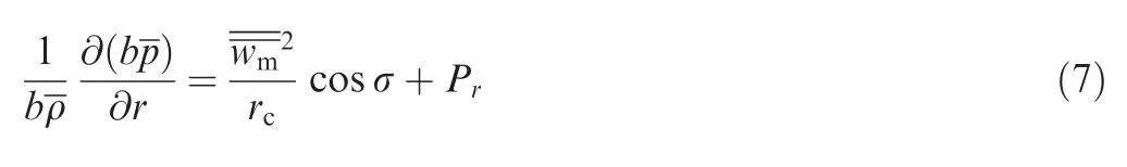
The inlet radial pressure gradient(GPR)is balanced with the radial component of the CF(Pr)source and CMR.Fig.7 shows the spanwise distributions of the inlet Pr,CMR,GPR and CMR+Prfrom 10%to 90%of the span.
As shown in Fig.7,the inlet Prpossesses a linear distribution along the span.For the straight cascade,the inlet Pris near zero,which indicates that the re is no radial component of CF source without bow.When the cascade is positively bowed,the Pris induced to turn negative in the lower half and positive in the upper half of the span.Negative bowed cascade possesses the opposite distribution of the Pr,while at midspan,the inlet Prstays zero in both positively and negatively bowed cascades due to geometrical symmetry.The gaps between the adjacent curves are nearly identical,which indicates that the value of Prvaries linearly as a function of bow angle.The boundary layer effects are mostly obvious in the distribution in the CMR,which reach about 20%of the span.The value of the inlet GPR is approximately equal to the sum of Prand CMR,which indicates that the inlet radial pressure gradient is determined by the combined effects of Prand CMR.

Fig.6 Spanwise distributions ofinlet Prand GPR for cascades without aerodynamic loading.
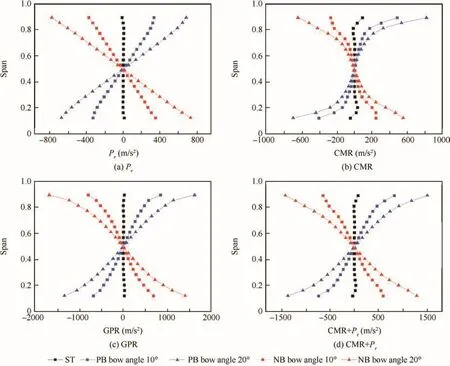
Fig.7 Spanwise distributions ofinlet Pr,CMR,GPR and CMR+Prfor cascades with different bow angles.
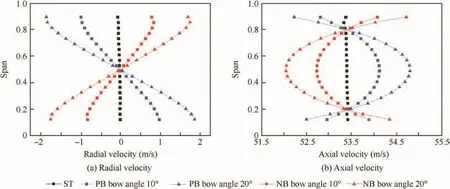
Fig.8 Spanwise distributions ofinlet radial velocity and axial velocity for cascades with different bow angles.
Fig.8 shows the spanwise distributions of the radial and axial velocities.For the straight cascade,the radial velocity is zero,which indicates that the re is no radial flow migration at the blade inlet.When the cascade is positively bowed,due to the pressure gradient from end walls to mid-span presented in Fig.7,the inlet fluid possesses a tendency to flow inwards and this trend gets stronger as the bow angle increases.As a result,morefluid flows through the mid-span region and larger mass flow provides larger axial velocity.On the other hand,the mass flow reduces at end walls in positively bowed cascades,leading to a deficit of the axial velocity.Negative bowing induces a reverse trend as a result of the opposite pressure gradient compared with positive bowing.From above,it is obvious that the inlet flow migration is the direct consequence of the radial equilibrium variation induced by blade bowing.
4.3.Effect of blade loading
A comparison of the effects of different blade loading is performed in this section.Three cases with the camber angles of 15°,30°and 45°were modeled for both PB20°and NB20°.The blade profile parameters and numerical conditions of the six cascade models are identical.Fig.9 shows the static pressure distribution in the blade to blade plane of the cascades with the camber angles of 15°,30°and 45°respectively.Fig.10 presents the comparison of the spanwise distributions of Pr,GPR,radial and axial velocities at the inlet of the cascades with different camber angles.
It can be noted in Fig.10 that the absolute values of Prand GPR increase as the camber angle changes from 15°to 45°for both positively and negatively bowed cascades.The comparison indicates that an increased camber angle will amplify the effects of blade bowing on the inlet flow equilibrium.As the camber angle increases,the inlet flow migration is enhanced as a result of the stronger pressure gradient.So it can be concluded that the effects of blade bowing on inlet flow variation are more sensitive to higher loading blades.In fact,as the camber angle increases,the pressure difference between the pressure and suction side is enlarged.According to Eq.(3),the radial bladeforce becomes stronger and leads to increasing absolute values of the inlet CF source.
4.4.Effect of inlet Mach number
In order to investigate the effects of the inlet Mach number on bowing mechanism,two cases with the inlet Mach number of 0.15 and 0.32 were modeled for both PB20°and NB20°.Othe r parameters including camber angle,inlet metal angle,inlet flow angle,etc.are identical.Fig.11 shows the spanwise distributions of the inlet Pr,CMR,GPR and radial velocity of the cascades with different inlet Mach numbers.
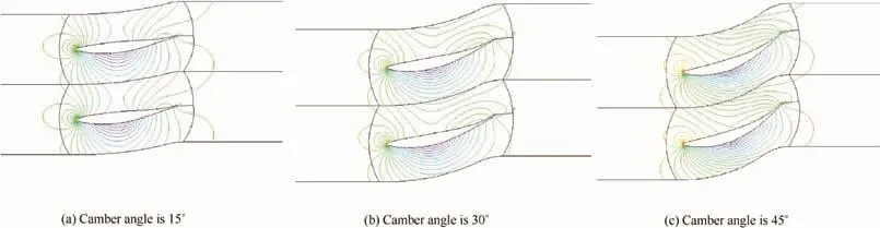
Fig.9 Pressure distribution for cascade with camber angles of 15°,30°and 45°.

Fig.10 Spanwise distributions of inlet Pr,GPR,radial velocity and axial velocity for cascades with different camber angles.

Fig.11 Spanwise distributions of inlet Pr,CMR,GPR and radial velocity for cascades with different inlet Mach numbers.
It is shown in Fig.11 that increasing Mach number magnifies the absolute values of Pr,CMR and GPR in both positively and negatively bowed cascades.The distribution of radial velocity indicates that the inlet flow migration is strengthe ned because of greater radial pressure gradient as Mach number increases.Numerical results suggest that the effect of blade bowing on the inlet flow is more efficient for high Mach number.However,this tendency is not infinite,because when the inlet Mach number is high enough,the boundary viscous effects will dominate the inlet flow migration,and the mechanism of blade bowing cannot be reflected.
5.Conclusions
Although bowed rotors and vanes have been widely used to control the secondary flows in fans/compressors and turbines,the mechanism of blade bowing is still meaningful for exploration.Based on the present paper,the inlet radial equilibrium variation induced by bowing is believed to be the key factor to change the blade performance.Comparative numerical studies have been carried out with simplified cascades to investigate the effects of bowing on the blade inlet radial equilibrium.The circumferentially averaged method was adopted for its distinct mechanism treating with potential flows.Some concluding remarks can be summarized as follows:
(1)The nonuniform pressure distribution inside the turbomachinery blade leads to the CF of the inlet flow.The inlet CF plays a significant role in the rebuilding of the inlet radial equilibrium when the blade is bowed.
(2)The inlet CF source contributes to the radial equilibrium of the inlet flow.Blade bowing changes the distribution of the inlet CF source and leads to the variation of the radial pressure gradient.As a consequence,the inlet flow migrates before the LE in bowed cascades.Positive bow drives inlet flow to migratefrom end walls to mid-span and negative bow leads to the reverse tendency.The inlet flow migration is believed to generate the incidence angle variation and affect the blade performance.
(3)The absolute value of the inlet CF source is amplified with the increase of the camber angle and inlet Mach number in bowed cascades.It is indicated that the effects of blade bowing on the inlet equilibrium are strengthe ned for high blade loading.This provides guidelines for designers to take good advantages of blade bowing by controlling the blade loading and the inlet Mach number.
Acknowledgments
This investigation was supported by the National Natural Science Foundation of China(Nos.51236001,51006005),the National Basic Research Program of China (No.2012CB720201)and Beijing Natural Science Foundation(No.3151002).
1.Deich ME,Gubarev AB,Filipov GA,Wang ZQ.A new method of profiling the guide vane cascades of turbine stages with small diameter-span ratio.Teploenegetika 1962;8(8):42–6.
2.Breugelmans FAH,Carels Y,Demuth M.Influence of dihedral on the secondary flow in a two-dimensional compressor cascade.J Eng Gas Turb Power 1984;106(3):578–84.
3.Shang E,Wang ZQ,Su JX.The experimental investigations on the compressor cascades with leaned and curved blade.Proceeding of the ASME 1993 international gas turbine and aeroengine congress and exposition;1993 May 24–27;Cincinnati,Ohio,USA.New York:ASME;1993.
4.Weingold HD,Neubert RJ,Behlke RF,Potter GE.Bowed stators:An example of CFD applied to improve multistage compressor efficiency.J Turbomach 1997;119(2):161–8.
5.Fischer A,Riess W,Seume JR.Performance of strongly bowed stators in a four-stage high-speed compressor.J Turbomach 2004;126(3):333–8.
6.Tan C,Yamamoto A,Mizuki S,Chen H.Influences of blade bowing on flowfields of turbine stator cascades.AIAA J 2003;41(10):1967–72.
7.Tan C,Yamamoto A,Chen H,Mizuki S.Flowfield and aerodynamic performance of a turbine stator cascade with bowed blades.AIAA J 2004;42(10):2170–1.
8.Tan C,Zhang H,Xia H,Chen H,Yamamoto A.Blade bowing effect on aerodynamic performance of a highly loaded turbine cascade.J Propul Power 2010;26(3):604–8.
9.Schobeiri MT,Suryanarayanan A,Jermann C,Neuenschwander T.A comparative aerodynamic and performance study of a threestage high pressure turbine with 3-d bowed blades and cylindrical blades.Proceedings of ASME turbo expo 2004:Power for land,sea,and air;2004 Jun 14-17;Vienna,Austria.New York:ASME;2004.
10.Vand MH,Wang S.Numerical study of the effects of bowed blades on aerodynamic characteristics in a high pressure turbine.Proceedings of ASME turbo expo 2005:Power for land,sea,and air;2005 Jun 6-9;Nevada,USA.New York:ASME;2005.
11.Chen L,Liu XJ,Yang AL,Dai R.Flow performance of highly loaded axial fan with bowed rotor blades.Mater Sci Eng Conf Ser 2013;52(4):66–71.
12.McNulty GS,Decker JJ,Beacher BF,Khalid SA.The impact offorward swept rotors on tip clearance flows in subsonic axial compressors.J Turbomach 2004;126(4):445–54.
13.Gallimore SJ,Bolger JJ,Cumpsty NA,Taylor MJ,Wright PI,Place JMM.The use of sweep and dihedral in multistage axial flow compressor blading–Part I:University research and methods development.J Turbomach 2002;124(4):521–32.
14.Ramakrishna PV,Govardhan M.Numerical study of the stagger angle effects in forward swept axial compressor rotor passages.Proceedings of ASME turbo rxpo 2010;2010 Jun 14–18;Glasgow,UK.New York:ASME;2010.p.1–11.
15.D’Ippolito G,Dossena V,Mora A.The in fluence of blade lean on straight and annular turbine cascade flow field.J Turbomach 2011;133(1):011013.
16.Gui X,Zhu F,Wan K,Jin D.Effects ofinlet circumferential fluctuation on the sweep aerodynamic performance of axial fans/compressors.J Therm Sci 2013;22(5):383–94.
17.Chang H,Zhu F,Jin D,Gui X.Effect of blade sweep on inlet flow in axial compressor cascades. Chinese J Aeronaut2015;28(1):103–11.
18.Steinert W,Eisenberg B,Starken H.Design and testing of a controlled diffusion airfoil cascadefor industrial axial flow compressor application.J Turbomach 1991;113(4):583–90.
19.Edwards JR.A low-diffusion flux-splitting schemefor Navierstokes calculations.Comput Fluids 1997;26(6):635–59.
20.Jin HL.Application of circumferentional average method in multistage axial fan/compressor design and analysis[dissertation].Beijing:Beihang University;2011[Chinese].
5 May 2016;revised 31 December 2016;accepted 20 February 2017
Available online 23 August 2017
Axial compressor;
Bowing;
Cascade;
Circumferential fluctuation;
Inlet flow;
Radial equilibrium
*Corresponding author.
E-mail address:jdh@buaa.edu.cn(D.JIN).
Peer review under responsibility of Editorial Committee of CJA.
Production and hosting by Elsevier
http://dx.doi.org/10.1016/j.cja.2017.07.014
1000-9361©2017 Production and hosting by Elsevier Ltd.on behalf of Chinese Society of Aeronautics and Astronautics.This is an open access article under the CC BY-NC-ND license(http://creativecommons.org/licenses/by-nc-nd/4.0/).
©2017 Production and hosting by Elsevier Ltd.on behalf of Chinese Society of Aeronautics and Astronautics.This is an open access article under the CC BY-NC-ND license(http://creativecommons.org/licenses/by-nc-nd/4.0/).
 CHINESE JOURNAL OF AERONAUTICS2017年5期
- CHINESE JOURNAL OF AERONAUTICS的其它文章
- Effect of an end plate on surface pressure distributions of two swept wings
- Determination of a suitable set of loss models for centrifugal compressor performance prediction
- A model offlow separation controlled by dielectric barrier discharge
- Research on parafoil stability using a rapid estimate model
- Transonic buff et control research with two types of shock control bump based on RAE2822 airfoil
- Tomography system for measurement of gas properties in combustion flow field