碳纳米管纱在应力下的压阻效应:现象和影响因素
2018-05-02 07:28JudeAnikeKalayuBelayJandroAbot
新型炭材料 2018年2期
Jude C. Anike, Kalayu Belay, Jandro L. Abot
(1. Department of Mechanical Engineering, The Catholic University of America, Washington, DC20064, USA; 2. Department of Physics, Florida A&M University, Tallahassee, FL32307, USA)
1 Introduction
Carbon Nanotubes (CNTs) have been receiving increased consideration for structural health monitoring owing to their multifunctional properties and tailorable aspect ratio. They exhibit a unique change in their electrical resistivity under mechanical strain. This piezoresistive response can be tailored towards integrated sensing. However, when it comes to the observable factors that affect the electrical behavior of CNT fibers in a physical system[1-3], attention has been drawn mainly to temperature, mechanical properties and cyclic effects. Due to their complex morphology and delicate metrology, it is unsurprising that less attention has been paid to characterizing the properties of a macroscopic CNT assembly. There are several ways to produce CNT yarn but currently, dry-spun yarns have shown to possess the best mechanical properties[4-9]. Dry spun CNT yarn from spinnable arrays are produced by growing the nanotubes on a substrate in a chemical vapor deposition (CVD) reactor with the aid of a catalyst. A carbon source introduced into the reactor undergoes catalytic decomposition into carbon atoms generating tubules of CNTs at the catalyst locations. The nanotubes on the substrates are vertically-aligned into brush-looking short nanotubes that is referred to as forest or array[9]. To form a long continuous fiber, CNTs are drawn from these arrays in an end-to-end connection bound by weak van der Waals forces. The continuous web of CNTs are termed ribbons and they can be aggregated into bundles to form threads that could be spun into loosely bound fibers. The mechanical properties of CNT fibers are limited by imperfections in their structures like defects, discontinuities, twist, entanglements, misalignments, fiber packing density and orientation[10-16]. Defects are often present in the form of voids and residual metal catalyst particles. Discontinuities stem from the form of nanotubes as they do not span the gauge length of the fiber. The strength of a CNT fiber is derived from the strength of its constituent CNTs and the frictional forces between them. CNT fibers also have low packing density (volume fraction or specific weight) emanating from the CNTs separation or contact length. Low inter-tube friction causes a reduction in the tensile strength of CNT fibers. To minimize this effect, the spun fibers are twisted and densified to increase the actual contact length. Twists induce cohesion between CNTs and CNT bundles to prevent disintegration under lateral forces[9]. With improved cohesion, the elasticity of the fiber is enhanced by initiating uniform load bearing capability across the fiber’s length. Twisted and often densified fiber bundles are called CNT yarns. Due to the rough nature of the yarn, even after twisting, uniform radial properties cannot be guaranteed. There is also a measured approach to twisting because over-twisting can introduce stress concentrations. The reported maximum value of the specific elastic modulus occurs at a twist angle of approximately 10°, while the maximum specific strength occurs at an angle of about 20°[11,17]. In the context of this work, CNT yarn refers to a fiber spun from a CNT arrays and condensed. Condensation can be achieved via twist, solvent densification or both.
From a displacement point of view, it has been shown that the loading rate affects the mechanical properties of fibers[18-21], and specifically CNT yarns[22-25]. The deformation mechanisms on the atomistic scale can be related to breaking of bonds, atomic rearrangements and dislocation movements. An increase in strain rate increases the yield strength of the CNT yarn. Zhang et al.[23]and Wang et al.[25]reported that high or dynamic strain rates improve the tensile properties while at the lower or quasi-static rates, they experience a higher fracture strain. For a material that exhibits piezoresistivity, these changes in mechanical properties are coupled with a change in its electrical properties. For sensing and actuation applications, it is pertinent to ascribe a rate of loading, within which the piezoresistive nature and behavior of the material can be predicted. Similar studies on the rate-dependent effects[22,23,25]have focused on the mechanical properties of CNT fibers while studies on the coupled electromechanical effects in CNT yarns under tensile deformation have either been conducted at a single loading rate[16]or focused on one strain rate regime in different tests[22].
The aim of this study is to determine the effects of the varying strain rates, slippage, mechanical failure and fiber geometry on CNT yarn’s piezoresistivity. The comprehensive study on the effect of strain level and plasticity on the piezoresistive response of the CNT yarn are also done. This is to gain a deeper understanding of the piezoresistive behavior in CNT yarns and the underlying phenomena.
2 Experimental
2.1 Material
One-thread CNT yarns used in this study have diameters of approximately 25 μm and 47 μm with a twist angle of about 30°. The CNTs were grown into a vertically aligned CNT array on a substrate[4,5]. A 10 cm Si wafer having a 5 nm-thick alumina (Al2O3) buffer layer was used with an iron-based 1.2 nm thin film catalyst, both magnetron sputtered. The dicing process on the Si wafer substrates were performed by scribing and breaking into 5 cm-long and variable width (up to 3.75 cm) substrates, loaded into a CVD reactor. In the presence of Ar, the reactor was heated up to 400 ℃ for annealing. After 2 min, the temperature of the reactor was ramped to 750 ℃, then a mixture gas ( 300 sccm of C2H4and 1 000 sccm of Ar) was introduced for about 20 min. The growth was achieved at a pressure of 98.7 kPa. Upon growth completion, 30 sccm of H2O and 2 000 sccm of Ar were delivered during cooling to promote CNT array detachment. The as-received CNT yarns were dry-spun from the sides of 400 mm-high vertically aligned arrays composed of 15 nm-diameter multiwall carbon nanotubes (MWCNTs)[4,26]. Densification was achieved with acetone without altering the innate properties[27,28]. The CNT array consists of a distribution of nanotubes consisting of up to seven walls. A scanning electron microscopy (SEM) image of the one-thread yarn is presented in Fig. 1. Each spool (and each batch) of the CNT yarn used is 10 m-long. The calculated resistivity of the CNT yarn used in this study is about 1.7 × 10⁻³Ω cm.

Fig. 1 SEM images of CNT yarn: (a) ×1500; (b) ×8000. Images taken with JEOL JSM-7100FA FE SEM.
2.2 Experimental setup
The tensile test samples were made from a thick cardstock base with a diamond shape cut in the middle to provide a stage for the gauge length. The CNT yarn was centered along the centerline and taped on both ends. This configuration was to support the CNT yarn during fabrication of the sample and insertion into the test fixture, yet allowing the tested portion of the CNT yarn (the section that lies within the diamond cutout) to move freely in the vertical direction. A straight cut was made on the longitudinal arms of the diamond cardstock to ensure that the cardstock did not interfere with the loading and that elongation occurred only within the gauge portion. The contact between the wire and the CNT yarn was outside and within the cut-out gauge zone. Both the ends of the yarn and the wires were taped to the paper while the vertical cuts were temporary binder-clipped to avoid pretension while inserting them into the test frame (Fig. 2a).
An electrically conductive paint from Bare ConductiveTM, was used to bond the CNT yarn to the electrical wires. The rubbery texture of the paint makes it ideal against undesired mechanical effects like stiffness to the CNT yarn. The paint dries quickly at room temperature in 10-15 min. From unwinding from the spool to integration to the cardstock, any form of deformation that could alter the properties of the CNT yarn was avoided. Five samples were prepared for each test. Additional samples were prepared and used as needed. Three batches of CNT yarn were used in this study. Care was taken to compare results with samples made from the same section of the same batch.
2.3 Mechanical and electrical measurements
A Mechanical Testing Systems (MTS) Criterion 43 electromechanical universal testing machine (UTM) was used to perform the mechanical tests. A force transducer attached to the UTM was used to apply the load to the sample. 1-N and 5-N capacity load cells were used in the experiments. The electrical characterization tests were performed using a National Instruments 4 072 LCR (Inductance-Capacitance-Resistance) reader mounted on a NI-PXI 1 033 chassis. The LCR was connected to the CNT yarn sample through wire clips attached at both ends (Fig. 2b). The connection of the clips was attached to the test frame to avoid dangling. The wires moved along with the testing frame because the length was enough to ensure they measured up to the displacement stage during testing. To ensure that the load was properly transferred to the sample, the adapter grips from the MTS machine were clipped at the edges of the gauge length to eliminate any gap. This way, any distance between the gauge length and the load connection could be neglected.
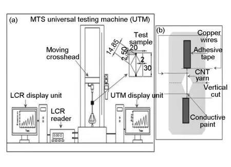
Fig. 2 Schematics of experimental setup.
2.4 Methodology
The MTS Criterion 43 was controlled via the TestWorks4 software and was programmed to apply a
uniaxial tension load to the sample at several displacement rates. The MTS MultiCycle package was used to apply both cyclic loading and load up to failure. The load applied to the sample and the cross-head extensions were recorded as a function of time. Additionally, the LCR reader simultaneously measured changes in resistance during the tests. Once the maximum load was reached, the loading machine stopped and then gradually unloaded the sample until the crosshead extension reached its original position. For accuracy, four-point probe measurements were used to eliminate contact resistance from the connecting wires. The results were analyzed using MATLABTMand Microsoft ExcelTM. All tests were performed at ambient temperature (20-25 ℃).
3 Results and discussion
3.1 Effect of slippage
The concept of slippage is very interesting and very important in describing the piezoresistive behavior in carbon nanotube yarns and fibers in general. It is also crucial in understanding the mechanism of adhesion between nanotubes. Carbon nanotubes are bound together by relatively weak van der Waals forces. For CNT yarns drawn from spinnable arrays, there is inter-tube friction between the CNT bundles (each CNT bundle consists of hundreds of individual nanotubes). The nature of the van der Waal and inter-bundle frictional forces is responsible for the measured properties of CNT yarns. It is also, in part, the reason their properties fall short of the excellent properties of individual carbon nanotubes. For example, the high axial tensile strength of individual CNTs and its stiffness (approximately 1 TPa for a single wall CNT, five times more than the stiffness of steel) is greater than any value reported for the CNT yarn[3-16]. While the covalent carbon bonds in individual nanotubes dominates their properties, they play little role in the properties of the CNT yarn.
Under a small deformation, the weak inter-tube bonding of the CNT bundles in the yarn allows them to experience sliding motion within the bundle, an action termed slippage. Slippage plays an important role in load transmission and stress distribution in CNT yarns. CNT yarns with a low packing factor will experience significant slippage. To reduce slippage, the contact between nanotubes must be improved for optimal frictional force engagement. One way to do that is by compaction through solvent densification or mechanical twist[28].
High twist in CNT yarn ensures minimal slippage due to fiber compaction or locking under tension. In a practical sense, however, there will always be slippage for instance at the grip locations during tests. This makes it much difficult to fully define the mechanics of CNT yarn deformation except if transverse isotropy is assumed throughout the yarn. Transverse isotropy can be achieved if the yarn is interminably twisted or the CNTs are perfectly interlocked that they all could experience uniform gripping pressure. Yarns though, have shown to start failing at high twist turns prior to a meaningful exertion of tensile force across its length[17]. To evaluate the effect of inter-tube slippage, the CNT yarn will be impregnated with an epoxy resin. This is to create a structure with stronger adhesion between CNT bundles.
The CNT yarn samples were dip-coated in the EPON 862/Epikure W system and tested under uniaxial tension. Uncoated CNT yarn samples were prepared for similar testing to compare the results. There were distinct differences in the strength, the ultimate strain and change in resistance of the CNT yarns. From Fig. 3a-c, it could be seen that the ultimate tensile strength of the CNT yarn increased when coated from 488 to 684 MPa. However, the fracture strain of the coated yarn reduced from 6.3% to 1.7%. Of importance to the context of this study is that the relative resistance change is higher in the dip-coated CNT yarn than that in the uncoated yarn. The maximum relative resistance change were about 4 at 6.3% strain for the uncoated CNT yarn compared to 0.6 at 1.7% strain for the coated yarn. However, this is because of the difference in the breaking strain. When the same strain level was compared for both CNT yarns (Fig. 3c), it was observed that the coated CNT yarn experiences a higher relative resistance change than the uncoated yarn. The linear region in the coated yarn persists to a higher strain level (0.2%-1.6%-strain) than in the uncoated one (1.2%-1.6%-strain). There was increased linearity when the CNT yarn is coated due to the fact that the matrix improved fiber adherence and reduced the propensity for the fibers to slip. The results indicate that the matrix-yarn interface/interphase plays an important role in the properties of the CNT yarn. CNT yarns are highly porous. Low molecular-weight polymer chains can infiltrate the fiber bundle, intercalate between nanotubes, and block load and charge-carrying channels. This will change the separation distance between adjacent CNTs, resulting in an increase in contact resistance due to tunneling. Fig. 3d shows that there is a considerable resin impregnation in the coated CNT yarn.
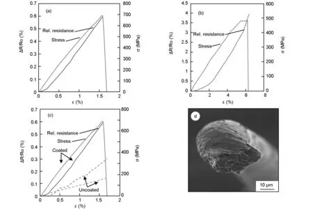
Fig. 3 (a-c) Relative resistance change and stress-strain curves of CNT yarn samples tested at 0.06 min-1 under tension to failure with the corresponding stress value: (a) coated, (b) uncoated, (c) both coated and uncoated CNT yarn up to 1.6 %-strain and (d) SEM image of the CNT yarn showing impregnation by the Epon 862/Epikure W system (×1 200).
3.2 Rate effects
CNT yarns experience strain rate strengthening[25]. Most fibers are expected to fail by the action of the load on the filaments; or in the case of CNT fibers, the carbon-carbon bonds that span most of the fiber length. CNT yarns with their high packing density, also experience failure by slip action between CNTs or CNT bundles. Under applied tensile forces, CNT yarns show a transition in fracture mode from pullout by shear between the CNTs, to a failure due to the fracture of the yarns themselves. This transition depends not only on the geometry of the CNTs but also on the rate of deformation of the CNT yarn. Higher tensile properties like the elastic modulus and strength of the CNT yarn are achieved at high strain rates while lower strain rates yield higher strains to failure[23]. For applications in sensing, it is imperative to determine the effect of the strain rate strengthening on the piezoresistivity of the CNT yarns, which has received no attention until now. The present studies were conducted using samples with a gauge length of 25 mm and subjected to several displacement rates including 15, 150, 1500, 15000 and 150000 mm min-1(with corresponding strain rates of 0.000 6, 0.006, 0.06, 0.6 and 6.0 min-1).
3.2.1 Sign of piezoresistivity
To determine the piezoresistive response of the CNT yarns under variable quasi-static strain rates, a cyclic loading up to a strain level of 1% was performed for 3 cycles. Fig. 4 shows the comparison of the results obtained at two different strain rates. At a strain rate of 0.006 min-1, the resistance increased during the loading segment and decreased as the load was released. This was in conformity to the previous understanding of traditional conducting fibers where upon application of the load, there would be a reduction in the contact length of the CNTs in the yarn, causing a tunneling distance across charge carriers. This separation of CNTs and their bundles leads to an increase in resistance. Since CNTs from arrays are short and do not span the yarn’s gauge length, their properties are defined by an overlay of extending neighboring nanotubes and actual contact with them. This makes the resistance contribution from the CNTs in the yarn (the intrinsic resistance) to be inconsequential in comparison to the inter-tube resistance. Thus, it can be assumed that contact resistance mostly accounts for the piezoresistivity.
At a very low strain rate, 0.001 min-1, a negative change in resistance was observed. This negative relative resistance change was observed in both the loading and unloading segments of the test. The negative piezoresistivity could be explained due to the time factor associated with low strain rates.

Fig. 4 Relative resistance change-strain curves at a 1%-maximum strain for strain rates of 0.001 and 0.006 min-1.
The rate of deformation or strain rate is the time derivative of the strain:
(1)
Due to the anisotropic nature of the CNT yarn and considering the Saint Venant’s principle, it will take a critical length for the stress to reach the entire CNT yarn uniformly due to the distance from the grips to the entire gauge length. It has been predicted that a critical length-to-diameter ratio of approximately 103is required to reach a uniform distribution of stress across the fiber[29]. This is in part due to the intricate morphology of yarns that allows the presence of discontinuities in the material to affect load transfer. It is
also likely that the frictional forces acting on the yarns may not be uniform since the yarn packing density is different across the radial length. Under low strain rate, the time associated with the displacement is so long that for load transmission to reach the critical length for normalized strain, the CNT yarns begin to experience relaxation. The relaxation is accompanied by rearrangement of networks of CNTs due to the increased possibility of sliding between the overlapping CNT bundles that produce new surface areas. If compaction is low, the tensile force will supersede the frictional forces and the reformation process will lead to slippage. Slippage with regards to load transmission and redistribution in CNT yarns is not useful as it leads to creation of materials with low strength. However, the structural form and ensuing mechanisms from such weak interactions are being considered for the development of self-organized CNT-based surface materials[30].
A decreasing resistance with strain have been previously reported for SWCNTs in parallel resistor network and attributed to change in band gaps of especially semiconducting nanotubes at high strain[31]. The results in this study shows that for MWCNT fibers, this phenomenon is rate-dependent.
It is important to determine the strain rate at which the piezoresistivity of the CNT yarn transitions from negative to positive. To achieve this, an additional spectrum of strain rates was tested within the low rates ranging from 0.000 6 to 0.001 6 min-1(Fig. 5).

Fig. 5 (a) Relative resistance change-strain curves for one cycle at 1 %-maximum strain for the following strain rates: 0.000 6, 0.001 and 0.001 6 min-1 and (b) Corresponding relative resistance history curves.
The negative resistance change persisted in the strain rate range of 0.000 6 to 0.001 min-1. It could be observed from Fig. 5b that the transition rate is at 0.001 min-1, after which the resistance increased during loading and decreased during unloading.
The change in resistance up to the point of failure was measured. However, since each section of the CNT yarn differs in strength and resistance at different strain rates, the CNT yarn has varying strain to failure. Therefore, a strain level at the proximity of the failure strain was chosen for uniformity. Tensile tests up to 2.5 %-strain at varying strain rates (Fig. 6), show that the relative resistance change is slightly higher at higher strain rates.

Fig. 6 Relative resistance change-strain to a maximum strain of 2.5 % for the following strain rates: 6, 0.6, 0.06 and 0.006 min-1.
From the results obtained, the following observations can be made:
The CNT yarns display higher sensitivity both at higher strain and at higher strain rates but marginally at higher strain rate.
The CNT yarns exhibit higher resistance change during the loading segments than during unloading segments for the higher strain rates (0.060, 0.600 and 6.000 min-1) where positive piezoresistivity was recorded. This effect is reversed for the lower rate (0.006 min-1) as the resistance change is more prominent during unloading.
The relative change in resistance decreases slightly during each successive cycle, i.e., the resistance change is higher during cycle 1, which is higher than that in cycle 2 and in turn higher than in cycle 3.
The explanation to the effect described in (b) is that at high strain rates, the CNT yarn experiences both higher deformation and strain hardening during loading. Upon unloading, the deformation causes enough elongation that the unloading trajectory becomes smaller than the deformed length. The strain hardening causes less deformation on subsequent loading cycles. This is quite understandable since the stress-strain hysteresis loop narrows successively for each new cycle[24]. The implication is that at a constant maximum strain, the energy needed to deform the CNT yarn in tension diminishes along with the strain for successive cycles. This explains the effect previously described in (c). In cyclic loading, the highest extension is achieved during the first cycle and that order is maintained as preceding cycles lead each further cycle in deformation.
The sensitivity of the CNT yarn also known as the gauge factor is given by:

(2)
whereR0is the initial resistance,ΔRis the change in resistance,εis strain, which is defined as the ratio of the change in lengthΔLover the original lengthL,GFis the gauge factor, which provides a measure of the sensitivity of the CNT yarn to measure strain.
The gauge factors were computed for each of the strain rates tested, and are presented in Fig. 7. There is only a slight difference in the values of the gauge factors from 0.000 6 to 6 min-1although the linear correlation increased with increasing strain rate. The inset in Fig.7 is the strain rate in logarithmic scale, showing the trend in the gauge factor. It can be inferred from this result that strain rates has little effect on the gauge factors. However, the linear association of values needed for sensing applications improved at higher strain rates. The gauge factors were similar for all further cycles tested, which is good for the robustness required for CNT yarns to be used as sensors.

Fig. 7 Gauge factors of CNT yarns at various strain rates with correlation coefficients.
It is proposed that two phenomena govern the electrical response of the CNT yarns: (1) an increase in resistance due to a decrease in contact length attributed to an elastic expansion of the carbon nanotubes bundles during the loading segments and a corresponding decrease in resistance due to increase in contact area by the contraction of the carbon nanotubes bundles during the unloading segments; and (2) a decrease in resistance due to inter-tube/inter-bundle slippage (inelastic shear motion) caused by yarn’s relaxation and structural reformation during the loading segments, and a continuous decrease in resistance during unloading as the yarn recovers its (conductive) structure. In the case of the higher strain rates, the first phenomenon dominates during both the loading and unloading segments. At very low strain rates, the second phenomenon dominates the loading segment and since this action is irrecoverable, any increase in resistance during the unloading segment is not expected or feasible.
3.2.2 Failure modes
In the preceding section, it was observed that for all strain rates tested, there is a consistent decrease in maximum resistance for each new cycle, which is consistent with the stress-strain results obtained in cyclic loads and may be caused by the permanent strain induced in the CNT yarn due to slippage. However, the change in resistance values remained relatively similar. It was also observed that the resistance changes at the lower strain rate (0.001 min-1) do not return to the origin or initial point for subsequent cycles unlike at the higher strain rate (0.006 min-1). This could be explained by the inability of the CNT yarn to recover fully due to effective slippage at low strain rates. To confirm these results, SEM images of the CNT yarns tested at the selected strain rates were taken at fracture locations. Images of the failure mechanisms of the CNT yarns tested at 0.000 6, 0.006, 0.06, 0.6 and 6 min-1strain rates are presented in Fig. 8. A ductile-like (gliding) mode of failure was observed at lower strain rates (0.000 6 and 0.006 min-1), but it starts to disappear as the strain rate increases through 0.06 min-1and vanishes at 6 min-1. At a strain rate of 6 min-1, a sharp cascading is seen and almost a brittle failure occurs. The ductile failure mode in CNT yarns could be explained by the relaxation phenomenon equalizing the rate of deformation because of structural collapse created by slippage. Consequently, a weak inter-tube adherence causes the CNTs and their bundles to fail under stronger sliding forces, which is not evident at higher strain rates. The slip or low shear interaction could also be assisted by the nature of the grip at the gauge ends. Since it is possible that the nanotubes closer to the surface of the yarn could be held differently in the grip to those closer to the center of the yarn, the CNTs that are not perfectly gripped will start to slip first. Comparing Fig. 8a with Fig. 8e, the Poisson’s effect appears to be more pronounced in Fig. 8a because of the detached nature of the pulling out of the CNT bundles in sliding motion prior to the ductile-like failure. It has also been suggested that in yarn-like fibers, the Poisson’s ratio does not depend on the slipping failure effect but strictly on the geometry of the yarn[32,33]. Due to the low-to-moderate twist angle of the CNT yarn, the twist is lost under tension prior to effective slippage as seen in the final shape of the CNT yarn itself after failure and evidenced by the ductile fracture (Fig. 8a,b). This weak twist interaction stems from the fact that the CNT yarn is expected to respond to the load by an initial separation along the twist angle as twisting is along its axial direction. At the region of ductile-like failure, slippage causes low shear friction on the carbon nanotubes, leading to elongation at the CNT yarn ends and a decrease in the CNT yarn’s cross-sectional area before failure.

Fig. 8 SEM images of the cross-sectional section and the longitudinal surroundings of the CNT yarn after fracture
CNT yarn mechanics is quite complex because unlike filament yarns with strength that depends solely on the strength of the constituent fibers, CNT yarns’ strength depends on many other factors like the bond between the fibers, the interaction between fibers (inter-fiber friction, stress concentration and lateral constraint), the interaction between the fiber and the yarn structure, flaw distribution along fiber length, etc. It is stipulated that the strength of a CNT yarn from a spinnable array obeys the weakest link theorem[17, 34]. The weakest link theorem postulates that the strength of a yarn is dictated by the weakest cross-section of the yarn structure. This means that a flaw size increases with length and a yarn under tension will most likely break at its weakest link. There is also the fiber fragmentation theorem that describes the failure strengths of yarns especially yarns of filaments with discrete length[35]. The fiber fragmentation theorem stipulates that fibers can break repeatedly with increasing strain before the actual final failure of the yarn. In this mechanism, a broken fiber under deformation can still build up tension, carry load, break into short segments and contribute to overall yarn’s strength. To explore these theorems, CNT yarn samples with the same gauge length were tested to failure at varying strain rates. Results from Fig. 9a,b, shows that at lower strain rates, the samples exhibit higher breaking strain. But in this case, there is not a definite correlation between strength and the strain rates unlike the comparison between coated and uncoated CNT yarns. An observation of the load-strain curve after initial failure, showed that there may be an evidence that mechanical load was still carried by some unbroken fibers before complete fracture. Fig. 9c displays the persisting load signal after failure which was visible under high strain rates and not so much at lower strain rates. This could corroborate the difference in failure mode obtained in Fig. 8. At lower strain rates, increased slippage coming from the weak frictional interaction leads to failure dominated by the fiber rather than the yarn. However, the electrical resistance stopped reading after the initial failure probably due to breakdown of structural interface to provide contact resistance. The results could be a confirmation that the fragmentation mechanism is purely a mechanical effect and has no visible correlation to the piezoresistivity of the CNT yarn especially after failure.

Fig. 9 (a) Stress-strain curves for samples tested to failure at 0.6, 0.06 and 0.006 min-1; b) Corresponding relative resistance curves and (c) load-strain curves showing the fragmentation process.
3.3 Piezoresistive hysteresis
To study the effect of increasing strain on the CNT yarn, tests were conducted at maximum strains of 0.1%, 0.5% and 1.0 % at a strain rate of 0.006 min-1. Six samples were tested at 0.1 %-strain, and eight at both 0.5 %-strain and 1.0 %-strain.
At 0.1%-strain level in a cyclic loading, the stress-strain curve for one cycle is shown in Fig. 10a. The absence of significant hysteresis is quite expected since there is very low stress built up in the sample at a very low strain. Thus, there is minimal dissipation of energy in the CNT yarn. In the relative resistance change-strain curve, an initial decrease in the resistance was observed. It had been suggested that since metallic CNTs have the lowest resistance, the piezoresistivity at low strain comes from them as they initially close their pseudo-bandgaps at the onset of strain before the gap opens and a resistance increase is recorded[16].
The stress-strain curve corresponding to a maximum strain of 0.5 % exhibits even more pronounced features with an increase in the strain (Fig. 10b), giving birth to an increased hysteresis loop. This hysteretic loop may be attributed to energy dissipation. More energy is absorbed during loading than energy released upon unloading. At a strain of 0.5 %, the increased strain in the CNT yarn is sufficient for plastic deformation to occur. As the strain level increases, the stress also increases. There is an appreciable increase in the relative resistance change, 0.019 at a maximum strain of 0.1 % compared to 0.05 at a maximum strain of 0.5 %.
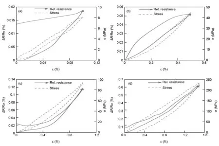
Fig. 10 Relative resistance change-strain curves with corresponding stress-strain curves for first cycle displacement test at strain rate of 0.006 min-1 for (a) 0.1 %- maximum strain; (b) 0.5 %-maximum strain; (c) 1 %-maximum strain and (d) 1.5 %-maximum strain.
The stress-strain curves at respective 1% and 1.5 % strains, (Fig. 10 b,c) showed a more prominent hysteresis curve than that observed at lower strain levels. This is due to higher stress introduced into the CNT yarn as the strain level was increased. As the stress value increased, hysteresis became prominent. During unloading, the CNT yarn would try to recover from the stretched or broken bonds to regain its initial state. Irrespective of the reversible strain, the total energy dissipated in the material under deformation is not recoverable. The deformation process starts with unraveling of twists and then reduction in cross-sectional area. Unlike in the strain rate effect, the Poisson’s effect is higher at high strain levels due to the significant amount of deformation involved. Hysteretic behavior is observed in both the mechanical and piezoresistive responses but it evolves oppositely with increasing strain level. The hysteresis loop associated with the mechanical response of the CNT yarn increases with increasing strain level while the piezoresistive hysteresis decreases with increasing strain (Fig. 10a-d).
These changes observed in the strain level, stress and resistance play a key role in the piezoresistivity of the CNT yarn. For the samples tested to a maximum strain of 1% and 1.5%, the relative resistance change was much larger as seen in Fig. 10 with the gauge factor reaching a value of 0.45. CNT yarns exhibit higher sensitivity at higher strain as expected.
To investigate the correlation and discrepancy in the resistance-stress and resistance-strain relationship reported previously[16], the relative resistance change-strain curves are presented alongside the relative resistance change-stress curves in Fig. 11.
It could be observed that the hysteresis of the relative resistance-strain curve disappeared at higher maximum strains from 1%- 1.5% while the stress-strain hysteretic behavior (displayed as insets) was fully captured on the relative resistance-stress curves.

Fig. 11 Relative resistance change-stress curves for first cycle displacement test at strain rate of 0.006 min-1 for
Due to the onset of plasticity at high strains, the stress-strain relationship becomes non-linear, while the piezoresistivity comes from stress contributions rather than the strain. It is seen that within the elastic region, 0.1%-strain for example (Fig. 11).

Table 1 The gauge factors of CNT yarns at various strain levels.
The corresponding relative resistance-strain curve and the relative resistance-stress curve were identical. This is because the stress is directly proportional to the strain in this region. Beyond the elastic region, the strain may not account for the entire piezoresistive effect. It was also noticed that the unloading curve of the piezoresistive hysteresis appears not to return to the origin and often returns to a higher relative resistance value than that of the loading curve. This is the opposite of the observed unloading curve of the mechanical hysteresis, where the unloading path was below the loading curve and always returned to the origin for the first cycle. The analysis of the computed gauge factors for the strain levels tested shows that unlike the strain rate, the strain level itself accounts for the variance in the gauge factor values (Table 1).
The effect of strain rate on the hysteretic behavior of the CNT yarn was also studied. Testing was done using strain rates of 0.006, 0.06 and 0.6 min-1up to 1%-strain level. There was no significant difference in the mechanical hysteresis behavior for all the strain rates tested. This could be seen from the superimposition of the hysteresis curves (Fig. 12a). There was also no noticeable difference in the piezoresistive hysteresis loop over the range of strain rates tested as presented in Fig. 12b. The superposition of the curves shows that the piezoresistive hysteresis of the CNT yarn can be described as strain rate-independent. At the maximum 1%-strain level tested, the stress in the specimen remained relatively similar for all strain rates as observed from the hysteresis loop.Since high displacement velocity (high strain rates) minimizes the impact of slippage, stress is well distributed at higher strain rates than at lower strain rates. The high displacement velocity could give rise to high internal friction. Disproportionate internal friction at varying strain rates will lead to the difference in the sizes of the hysteresis loop.

Fig. 12 Effect of strain rate on its piezoresistive hysteresis.
3.4 Geometrical effects
The piezoresistivity of CNT yarn depends not only on its stress/strain level but also on the change in its geometry, band gap, temperature, et al.[36-43]. The effect of geometrical parameters such as length and the cross-sectional area of the CNT yarn on its piezoresistivity was evaluated.
Increasing the aspect ratio (length/diameter) of the CNT yarn, will increase the area available for frictional forces to engage between the nanotubes. Consequently, a longer CNT yarn will experience increased friction. For CNT yarns with varying diameters, the assumption is that piezoresistivity is proportional to stress/strain and that stress is proportional to the amount of friction in the structure.
To study the impact of cross-sectional area on the CNT yarn’s resistance response, a simple assumption is made. It is assumed that the load that transfers from each CNT bundle inside the CNT yarn is proportional to the contact area while the stress level in the bundle is equal to the ratio of the applied load to the cross-sectional area. Also, considering the relationship between resistance,R, and cross-sectional area,A, an increased cross-sectional area (diameter) would amount to a decrease in the resistance for a constant resistivity.
CNT yarns of different diameters, 25 ± 5.3 μm and 47 ± 4.1 μm, synthesized similarly were used in this study. Five CNT yarn samples with a length of 25 mm were prepared and tested to failure under the same testing parameters as in prior sections. The mechanical test results in Fig. 13 confirmed that tensile elastic modulus and strength are higher for fibers of smaller diameter[44]due to assumed higher compaction in fibers of lesser thickness. Although the modulus and strength are higher for the yarn of smaller diameter, CNT yarn A (47 ± 4.1 μm-diameter) exhibits a higher resistance change than CNT yarn B (25 ± 5.3 μm-diameter). It is clear from Fig. 13b, that more load was transferred to CNT yarn B, but the corresponding resistance change did not indicate so.

Fig. 13 Effect of CNT yarn’s diameter on its piezoresistive response.
This may indicate that the previous notion of an increased cross-sectional area resulting in a decrease in resistance change does not hold for a CNT yarn due to its resistance being accounted for by mostly contact resistance. The CNT yarn with high diameter, due to the higher CNT fiber volume, experiences more friction in tension and as such, exhibits a better stress-to-resistance transmission mechanism.
Another set of CNT yarn samples with three different gauge lengths, 10, 15 and 25 mm, were prepared to compare the effects of varying length on the piezoresistivity of the CNT yarn. It is expected that any material with random defects would be weaker with length. However, the CNT yarn did not exhibit an increasing tensile strength with decreasing gauge length. From the relative resistance change curve of Fig. 14, it is observed that the longer the CNT yarn, the greater the resistance change. The 15 mm-long CNT yarn sample exhibited a similar response to that of 10 mm-long CNT yarn. However, the difference became very pronounced when the relative resistance readings were compared with those of the 25 mm-long
CNT yarn samples. This could be explained by the additional contact area that the longer CNT yarn provides for charge carriers to either separate or come in contact during the tests. It was important to determine the transition displacement rate at which the piezoresistivity sign was changed for each of the gauge length tested. The results are shown in Table 2.
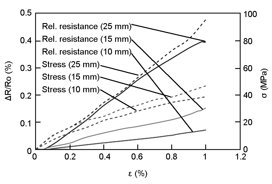
Fig. 14 Relative resistance change-strain and stress-strain curves at 0.006 min-1 to 1 %-maximum strain.
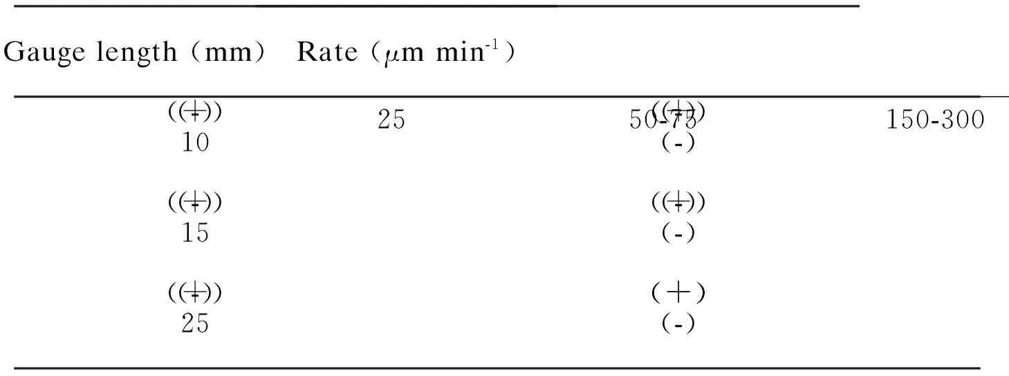
Table 2 Piezoresistivity sign of CNT yarns in terms of displacement rate and gauge length.
The 10 mm- and 15 mm-long CNT yarns have a lower transition displacement rates than the 25 mm-long CNT yarn. This could be explained by the limited effect of sliding in higher gauge lengths due to increased contact lengths. The interfacial contact means that stress redistribution is engaged more uniformly than at shorter gauge lengths, which provide less contact area. This is demonstrated by a higher sensitivity of the 25 mm-long CNT yarn, with a higher gauge factor of 0.4, compared to 0.13 of the 15 mm-long CNT yarn and 0.07 of the 10 mm-long CNT yarn.
4 Conclusions
An experimental study was conducted to determine the piezoresistive response of CNT yarns and the effect of strain rate, strain level, load transfer mechanisms and geometrical parameters on that response. The change in electrical resistance was studied as a function of strain level in CNT yarns that were subjected to uniaxial tensile quasi-static loading. The resistance of the CNT yarn increased with increasing strain and decreased during unloading as the material recovered its conductive structure. The change in resistance is associated with an increase in tunneling distance of charge carriers, which in the case of CNT yarn, could be attributed to the interfacial contact of CNTs. Understanding the role slippage in the behavior of CNT yarns is crucial in tapping its piezoresistive properties. In the presence of a matrix, the gauge factors are higher for the CNT yarn. There is also increased linearity for CNT yarns coated with a polymer when compared to the uncoated one for the same strain level.
It was observed that the resistance change is associated with not only an increase in strain but also in stress. Beyond the elastic region, the proportionality of strain with stress becomes tenuous due to effect of slippage and morphological changes. Slippage alters the load transfer mechanism, thus a correlation of resistance with stress becomes more appropriate. It was observed that the hysteresis loop associated with the mechanical response of the CNT yarn is directly proportional to the strain level while the piezoresistive hysteresis is inversely proportional to the strain. Compared to the mechanical hysteresis, the unloading curve of the first cycle of the piezoresistive hysteresis appears to follow a different path, most times higher than the loading curve while the unloading curve of the mechanical hysteresis always returns to the origin.
Strain rate plays a significant role in the piezoresistivity of the CNT yarn. At very low strain rates, a negative piezoresistivity was observed. The decreasing resistance was seen in both the loading and unloading segments at a strain rate of 0.001 min-1. This was attributed to the slippage and structure reformation of the CNT yarn. High CNT yarn slippage introduces uneven stress distribution, which allows the CNT yarn to reshape under load. Under this condition, the failure of the CNT yarns depends on the CNT bundles. At 0.006 min-1, a positive piezoresistive response was observed as the load exerted on the CNT yarn was much uniformly transferred to the structure through interfacial contacts of the CNT bundles. The resistance was directly proportional to the strain and stress during both loading and unloading segments.
It was also observed that the strain rate does not affect the gauge factor as much as the strain level does. There was in fact, very little or negligible change in the gauge factors when calculated at different strain rates. However, the gauge factors increased with increasing strain, peaking at 1%-1.5 %-strain before subsiding at strains above 2 %. CNT yarn of higher cross-sectional area (47 ± 4.1 μm-diameter) showed higher resistance change than those of lower cross sectional area (25 ± 5.3 μm-diameter). This may be explained by the contact nature of the resistance transfer in CNT yarns making the high-diameter yarn experience more friction under uniaxial tensile deformation. Slippage has a greater effect on shorter CNT yarns than longer ones due to less contact length in shorter yarns. Consequently, the shorter CNT yarns exhibit smaller gauge factors.
Piezoresistivity of the CNT yarn is much more complex than in traditional fibers due to their geometry. Within the limits of experimental work, this study underscores the importance of yarn structure and the CNTs as essential components of both stress transfer mechanisms and piezoresistive systems. Future studies will include modeling the observed effects that are associated with geometry to grasp fully the interplay of structure, load distribution and failure modes with the change in resistance. It is crucial to compare the results obtained for the CNT yarn to that of fibers without twist or even densification to corroborate some of the effects attributed to the yarn structure. By understanding the changes in the cross-sectional area of the CNT yarn while monitoring its mechanical and electrical characteristics, their correlation could be better understood. The results at these quasi-static strain rates will provide a good vista for studies involving the dynamic response of CNT yarns.
The authors thank Dylan Kemelor and all the students in the Intelligent Materials laboratory at The Catholic University of America for their logistical support to this study and Maureen E. Williams at the National Institute of Standards and Technology (NIST), Gaithersburg, Maryland, for the images. The authors acknowledge the financial support from the Air Force Office of Scientific Research (AFOSR) through Grants FA9550-10-1-0040 with program officer Dr. David Stargel and FA9550-15-1-0177 with program officers Dr. James Fillerup, Lt. Col. Jamie Morrison and Dr. Jaimie Tiley, and from the National Aeronautics Space Administration (NASA) District of Columbia Space Grant Consortium (DCSGC) through Grant 31154.
[1] Abot J L, Schulz M J, Song Y, et al. Novel distributed strain sensing in polymeric materials[J]. Smart Mater Struct, 2010, 19(8): 085007-1-085007-19.
[2] Abot J L, Song Y, Sri V M, et al. Delamination detection with carbon nanotube thread in self-sensing composite materials[J]. Compos Sci Technol, 2010, 70(7): 1113-1119.
[3] Zhao H, Zhang Y, Bradford P D, et al. Carbon nanotube yarn strain sensors[J]. Nanotechnology, 2010, 21: 305502.
[4] Li Y L, Kinloch I A, Windle A H. Direct spinning of carbon nanotube fibers from chemical vapor deposition synthesis[J]. Science, 2004, 304: 276-278.
[5] Jiang K L, Li Q Q, Fan S S. Nanotechnology: spinning continuous carbon nanotube yarns-carbon nanotubes weave their way into a range of imaginative macroscopic applications[J]. Nature, 2002, 419(6909): 1-801.
[6] Deng F, Lu W B, Zhao H B, et al. The properties of dry-spun carbon nanotube fibers and their interfacial shear strength in an epoxy composite[J]. Carbon, 2011, 49: 1752-1757.
[7] Vigolo B, Penicaud A, Coulon C, et al. Macroscopic fibers and ribbons of oriented carbon nanotubes[J]. Science, 2000, 290(5495): 1331-1334.
[8] Zhang M, Atkinson K R, Baughman R H. Multifunctional carbon nanotube fiber yarns by downsizing an ancient technology[J]. Science, 2004, 306: 1358-1361.
[9] Jayasinghe C, Chakrabarti S, Schulz M J, et al. Spinning yarn from long carbon nanotube arrays[J]. Journal of Materials Research, 2011, 26: 1-7.
[10] Koziol K, Vilatela J, Moisala A, et al. High-performance carbon nanotube fiber[J]. Science, 2007, 318(5858): 1892-1895.
[11] Lu W, Zu M, Byun J H, et al. State of the art of carbon nanotube fibers: opportunities and challenges[J]. Adv Mater, 2012, 24(14): 1805-1833.
[12] Wu A S, Tsu-Wei Chou. Carbon nanotube fibers for advanced composites[J]. Materials Today, 2012, 15: 7-8.
[13] Zheng L X, Zhang X F, Li Q W, et al. Carbon-nanotube cotton for large-scale fibers[J]. Adv Mater, 2007, 19(18): 2567-2570.
[14] Wu A S, Chou T W, Gillespie Jr J W, et al. Electromechanical response and failure behaviour of aerogel spun carbon nanotube fibres under tensile loading[J]. J Mater Chem, 2012, 22: 6792-6798.
[15] Jayasinghe C, Li W, Song Y, et al. Nanotube responsive materials[J]. MRS Bulletin, 2010, 35(9): 682-692.
[16] Lekawa-Raus A, Koziol KKK, Windle A H. Piezoresistive effect in carbon nanotube fibers[J]. ACS Nano, 2014, 8(11): 11214-11224.
[17] Miao, M. Yarn spun from carbon nanotube forests: Production, structure, properties and applications[J]. Particuology, 2013, 11: 378-393.
[18] Wang Y, Xia Y M. The effects of strain rate on the mechanical behaviour of Kevlar fibre bundles: an experimental and theoretical study[J]. Compos A, 1998, 29A: 1141-1415.
[19] Wang Y, Xia Y M. Experimental and theoretical study on the strain rate and temperature dependence of mechanical behavior of Kevlar fiber[J]. Compos Part A. Appl S, 1999, 30(11): 1251-1257.
[20] Zhu D J, Mobasher B, Rajan S D. Experimental study of dynamic behavior of Kevlar 49 single yarn. In: Proceedings, SEM annual conference, Indianapolis, USA[J]. Society for Experimental Mechanics, 2010: 147-152.
[21] Schwartz P, Netravali A, Sembach S. Effects of strain rate and gauge length on the failure of ultrahigh strength polyethylene fibers[J]. Text Res J, 1986, 56(8): 502-508.
[22] Wu A S, Nie X, Hudspeth M C, et al. Strain rate-dependent tensile properties and dynamic electromechanical response of carbon nanotube fibers[J]. Carbon, 2012: 3876-3881.
[23] Zhang Y, Zheng L, Sun G, et al. Failure mechanisms of carbon nanotube fibers under different strain rates[J]. Carbon, 2012: 2887-2893.
[24] Anike J C, Bajar A, Abot J L. Time-dependent effects on the coupled mechanical-electrical response of carbon nanotube yarns under tensile loading[J]. J Carbon Res, 2016, 2(1): 3.
[25] Wang P, Zhang X, Hansen R V, et al. Strengthening and failure mechanisms of individual carbon nanotube fibers under dynamic tensile loading[J]. Carbon, 2016, 102: 18-31.
[26] Yakobson B I, Campbell M P, Brabec C J, et al. High strain rate fracture and C-chain unraveling in carbon nanotubes[J]. Comp Mater Sci, 1997, 8(4): 341-348.
[27] Zhan Z Y, Zhang Y N, Sun G Z, et al. The effects of catalyst treatment on fast growth of millimeter-long multiwalled carbon nanotube arrays[J]. Appl Surf Sci, 2011, 257(17): 7704-7708.
[28] Hill F A, Havel T F, Hart A J, et al. Enhancing the tensile properties of continuous millimeter-scale carbon nanotube fibers by densification[J]. ACS Appl Mater Interfaces, 2013, 5: 7198-7207.
[29] Gspann T S, Montinaro N, Pantano A, et al. Mechanical properties of carbon nanotube fibres: St Venant’s principle at the limit and the role of imperfections[J]. Carbon, 2015, 93: 1021-1033.
[30] Buehler M J. Mesoscale modeling of mechanics of carbon nanotubes: Self-assembly, self-folding and fracture[J]. Journal of Materials Research, 2006, 21: 2855-2869.
[31] Cullinan M, Culpepper M. Carbon nanotube as piezoresistive microelectromechanical sensors: Theory and experiment[J]. Phys Rev B, 2010, 82: 115428.
[32] Pan N. Development of a constitutive theory for short fiber yarns: Mechanics of staple yarn without slippage effect[J]. Textile Res J, 1992, 62(12): 749-765.
[33] Pan N. Development of a constitutive theory for short fiber yarns. Part II: Mechanics of staple yarn with slippage effect[J]. Textile Res J, 1993, 63(9): 504-514.
[34] Peirce F T. Tensile tests for cotton yarns. Part 5: “Weakest link” theorems on the strength of long and of composite specimens[J]. Journal of the Textile Institute Transactions 1926, 17: 355-368.
[35] Realff M L, Pan N, Seo M, et al. A stochastic simulation of the failure process and ultimate strength of blended continuous yarns[J]. Textile Res J, 2000, 70(5): 415-430.
[36] Abot J L, Alosh T, Belay K. Strain dependence of electrical resistance in carbon nanotube yarns[J]. Carbon, 2014, 70: 95-102.
[37] Obitayo W, Liu T. A review: Carbon nanotube-based piezoresistive strain sensors[J]. J Sens, 2012: 652438.
[38] Vilatela J J, Windle A H. A multifunctional yarn made of carbon nanotubes[J]. J Eng Fiber Fabr, 2012, 7: 23-28.
[39] Yang L, Anantram M P, Han J, et al. Band-gap change of carbon nanotubes: effect of small uniaxial and torsional strain[J]. Phys Rev B, 1999, 60 (19): 13874-13878.
[40] Berger C, Yi Y, Wang Z L, et al. Multiwalled carbon nanotubes are ballistic conductors at room temperature[J]. Applied Physics A, 2002, 74(3): 363-365.
[41] Koratkar N, Modi A, Lass E, et al. Temperature effects on resistance of aligned multiwalled carbon nanotube films[J]. Journal of Nanoscience and Nanotechnology, 2004, 4(7): 744-748.
[42] Li X, Levy C, Elaadil L. Multiwalled carbon nanotube film for strain sensing[J]. Nanotechnology, 2008, 19(4): 045501.
[43] Loh K J, Kim J, Lynch J P, et al. Multifunctional layer-by-layer carbon nanotube-polyelectrolyte thin films for strain and corrosion sensing[J]. Smart Mat Struct, 2007, 16(2): 429-438.
[44] Zu M, Li Q, Zhu Y, et al. The effective interfacial shear strength of carbon nanotube fibers in an epoxy matrix characterized by a microdroplet test[J]. Carbon, 2012: 1271-1279.
猜你喜欢
核科学与工程(2021年4期)2022-01-12
今日农业(2020年19期)2020-12-14
商周刊(2017年5期)2017-08-22
中学物理·高中(2016年12期)2017-04-22
浙江大学学报(工学版)(2016年9期)2016-06-05
原子与分子物理学报(2015年3期)2015-11-24
少儿科学周刊·少年版(2015年2期)2015-07-07
快乐作文·低年级(2015年1期)2015-03-26
奥秘(2014年10期)2014-10-17
郑州大学学报(理学版)(2014年4期)2014-03-01