基于MEMS惯性传感器的高精度步长估计算法
2018-05-31 03:10路永乐陈永炜郭俊启
中国惯性技术学报 2018年2期
路永乐,陈永炜,邸 克,郭俊启,余 跃,刘 宇
(重庆邮电大学 光电信息感测与传输技术重庆市重点实验室,重庆 400065)
In the future, the measurement and monitor of temporal and spatial information of the pedestrian gait is essential for self-contained pedestrian outdoor and indoor navigation system and emergency rescue[1-2].Global Navigation Satellite System, such as Global Position System (GPS) and Globalnaya Navigatsionnay Sputnikovaya Sistema (GLONASS), has been playing an important role in pedestrian outdoor navigation system.The satellite signals are unable to penetrate buildings so that the indoor navigation techniques, such as ZigBee,Wi-Fi, Beacon, inertial sensors and so on, are required for pedestrian indoor navigation system[3-6].
With the rapid development of micro electro mechanical system technology (MEMS), the inertial measurement unit (IMU) including MEMS accelerometers and gyroscopes is widely used for pedestrian navigation system due to its independence, portability,low cost and low power consumption, and it can be attached to the subjects that interact with an ubiquitous computing environment[7-8]. The pedestrian inertial navigation algorithm requires both the orientation and walking distance determination in pedestrian’s per movement cycle[9-11]. So one of the key difficulties in pedestrian inertial navigation system is to accurately calculate or estimate the step length (SL) during walking by using various systems and algorithms[12].
Existing methods for the SL estimation in literature[13] are generally based either on an inverted pendulum or on regressive models utilizing spatiotemporal parameters of inertial sensors signal. The step length can be obtained by step length estimation algorithms of various linear regressions, but these regressive models for SL estimation may be ineffective under general conditions,because the models’ statistical parameters should be adjusted according to the stride frequency, the variation and the extreme value of accelerometer signal.
The forward displacement during the single stance phase and the double stance phase, in level normal walking, can be modeled as an inverted pendulum through the bio-mechanic model of a kneeless biped[14].The leg and foot length parameters for the pedestrian need to be measured accurately, and the accuracy of traversed distance ranged from 94.5% to 106.7% of the actual traversed distance. Shin and Park proposed an adaptive step length estimation algorithm by utilizing optimal parameters and movement status awareness with the IMU attached to the subject’s waist belt[15]. The measured error for a subject’s walking distance was 4.8%with respect to actual walking distance. A novel method for step length was proposed by means of combining a Kalman filter with an optimally filtered direct and reverse integration applied to the sensor signals[16]. The step length was estimated for nine subjects with less than 3%error by using the proposed method. But the IMU must be positioned to the right side of the subject pelvis, and Y axis of IMU must be parallel to the direction of the pedestrian progression.
Prior works for the SL estimation are based either on a general regressive representation or on a simplified bio-mechanic model of the human gait. The above SL indirect estimation methods are restricted to the level normal walking of health subjects, or can require the subjects’ leg length. Conversely, the unrestricted and accurate measurement approach of space walking distance based on IMU is proposed to compensate for the defects encountered in prior algorithms.
1 Description of gait model and system
The pedestrian gait is a regular and frequent movement with complex and periodic characteristics. The gravity center of pedestrian body varies periodically in both horizontal direction and vertical direction during normal walking. The development of the inertial measurement technique is beneficial to the dynamic quantitative analysis with respect to various parts of the body. Most parts of the body, such as feet, legs and waist, have corresponding variations of the acceleration and angular velocity during walking. Each gait cycle can be divided into two phases: the stance phase and the swing phase including lifting, swing and dropping, as shown in Fig.1.
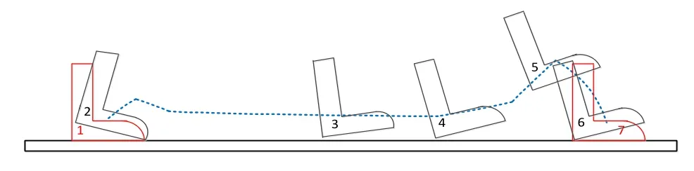
Fig.1 A gait cycle for pedestrian walking
In per normal walking cycle, the period of the stance phase is slightly less than the swing period. The swing phase of one gait cycle includes three states.Firstly, a gait cycle begins when a pedestrian lifts the heel from the stance phase; Secondly, the pedestrian moves feet from one location to another; thirdly, a gait cycle ends when heel strikes the ground, and finally it returns to the stance phase at the end of swing phase. The space trajectory of the sensor module mounted on the pedestrian instep is shown as blue line in Fig.1.
The procedure of the proposed algorithm in this paper includes the identification of gait events and time interval in per swing period and the determination of foot displacement along the direction of horizontal and vertical progression. However, the cumulative error grows quadratically over time in practice. Zero velocity update is proposed to periodically update the sensor module drift. The calculating method of step length described below can be applied into the data obtained from inertial sensor module. The algorithm structure is shown as the Fig.2.
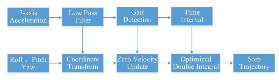
Fig.2 Block diagram of the algorithm
2 Gait detection
An micro attitude and heading reference system AHRS_Box featuring a tri-axial accelerometer, a tri-axial magnetometer and a tri-axial gyroscope (dynamic accuracies of roll, pitch and yaw angles are 0.5°, 0.5°, 3.0°,respectively, unit weight is 35 g, unit size is 47 mm × 43 mm × 17 mm, sampling data is at 400 frames/s) was used in the research of this paper. The sensor module was attached to a user’s shoe withX,YandZaxes pointing to forward, left and upward respectively. The data of the sensor module was stored in a laptop through Bluetooth,as shown in Fig.3.
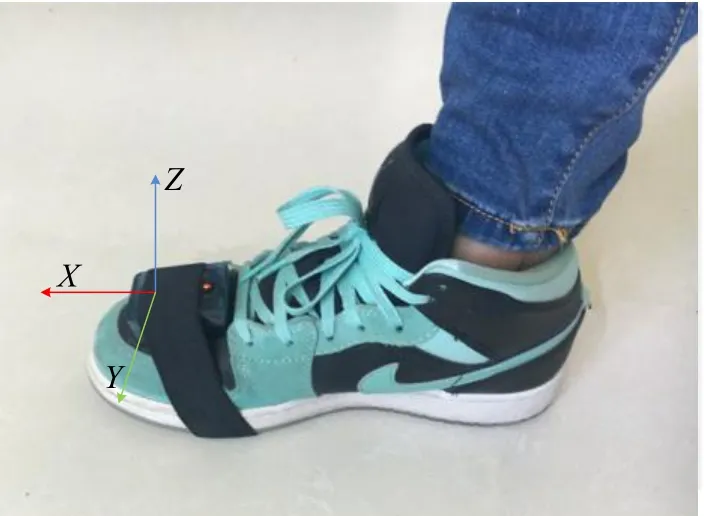
Fig.3 Sensor module mounted on the pedestrian instep
A gait cycle begins when the heel of a foot strikes the ground and ends when the same situation occurs again. Based on the swing and stance characteristics of the pedestrian walking, the three-axis accelerometer modulus values form a waveform of cyclical and regular changes. Therefore, the characteristics of the waveform can be used to detect the gait events. The detecting methods including flat zone detection, zero crossing detection and peak detection were generally utilized to detect the gait cycle. The zero crossing detection and the peak detection were generally used when the accelerometer was held in user’s hand or attached to the user’s waist. Since sensor module was mounted on the user’s instep in this paper, the flat zone detection was applied to detect the flat zone of the accelerometer modulus values during the stance phase. Three-axis accelerometer modulus values were shown as Eq.(1).
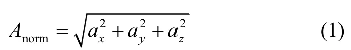
Whererepresent the output data of tri-axial accelerometer in theX,Y, andZdirections respectively.
Since the physiological frequency captured by the sensors associated to pedestrian movements is below 15Hz, the low-pass digital filtering technique with a 15 Hz cut-off frequency is utilized to remove the high frequency noise of the sensor data. The simulation of aceleration data is shown in Fig.4, in which one walking cycle is divided into two phases including the stance phase 1 and the swing phase 2, and is divided into four states including the lifting state A, the swing state B, the heel strike state C and the stance state D. The flat zone detection under the conditions shown in Eq.(2) is utilized to determine whether the foot is stationary on the floor.According to the abundant experiments and data analyses based on a large number of testers with different heights and walking at different speeds, the acceleration modulus values and their standard deviations are usually less than the threshold.
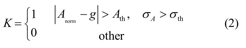
Wheregis local acceleration of gravity,is the standard deviation of acceleration modulus value,andstand respectively for the thresholds of standard deviation and acceleration modulus during swing phase 2.

Fig.4 Step detection based on accelerometer modulus values
However, a few false judgments, as shown in Fig.4,were caused by the slight jitter during walking. According to the study of pedestrian walking, the stride frequency of pedestrian does not exceed five steps per second. In order to get rid of these false judgments, the time threshold was set to eliminate the gauge errors.represents the time interval between the same foot’s leaving and thereafter hitting the ground,Whereshown as state A, B and C in Fig.4.stands for the time threshold.
3 Step length calculation
The proposed method for calculating the pedestrian displacement requires the acceleration along both the level direction and the vertical direction with respect to the global frame. The global frame was defined as follows: bothaxis andaxis coincide with the level direction which stands for the direction of pedestrians’ progression during level walking, andaxis coincides with the direction of gravity. Theaxis of global frame conform to the right-hand rule.
Since the sensor module was mounted on one of users’ insteps, theX,Y,Zdirections of tri-axial acelerometer were inconsistent withlevel direction andgravity direction of the global frame. The acceleration vectors of both reference coordinate systems need to be transformed. The following formula is the transformational matrix from global frame to the sensor reference frame.

Wherestand respectively for pitch, roll and yaw of the sensor orientation during the movement.
In order to acquire level component and vertical component of the accelerometer in the global frame,three components of the global frame are calculated according to the following formula:
Whereis the matrix transpose of the transformational matrix
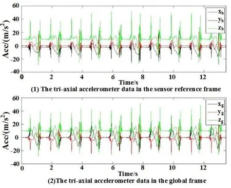
Fig.5 Accelerometer data in different frames
The differences resulting from this conversion are shown in Fig.5. Since the accelerometer vector of the sensor module contains gravity vector, the acceleration of gravity direction in the global frame is computed by subtracting the local acceleration of gravity. The acceleration signal in the sensor frame, however, contains bias and gain errors due to temperature calibration errors,bias instability, etc. The cumulative error caused by the zero-offset of inertial sensors grows quadratically in time so that it becomes infinity. When the pedestrian’s foot is stationary on the ground, the zero velocity update (ZUPT)is an effective method to eliminate and control the cumulative error. As mentioned above, the velocity and acceleration of the pedestrian’s per gait are zero when pedestrian’s foot is in the stance state.
According to the periodical characteristics of the pedestrian walking, the intervalof the swing state during one walking cycle has been detected in the step detection. The trajectory of the pedestrian’s foot was calculated by using optimized double integral for the sensor’s acceleration vectors in the global frame. The calculation formulae are as follows:
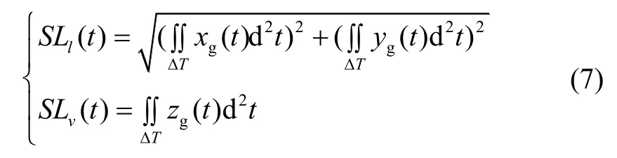
Whereare the sensor’s acceleration vectors in the global frame,SLlandSLvstand respectively for the level displacement and the vertical displacement of MEMS sensor module in the global frame during one step cycle.
Based on the zero velocity update and the optimized double integral, per step trajectory of the pedestrian’s foot was calculated, and per step length of the pedestrian was the level displacement of sensor module during per gait cycle. The level displacement and the vertical displacement of the pedestrian foot were shown in Fig.6. The changing trends of the simulation result and the actual moving track in Fig.1 are consistent. Per walking cycle included the lift off state A, the swing state B, the heel strike state C, and the stance state D.
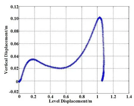
Fig.6 Trajectory of the pedestrian foot
4 Testing results
In order to verify the performance and the adaptability of the proposed step length calculation method, a large amount of outdoor and indoor tests on ten healthy subjects (169±10 cm tall) were conducted. Tests were conducted both on the University’s football ground and laboratory building. The AHRS_Box MEMS sensor was strapped to the instep of subjects, as shown in Fig.3. The acceleration, attitude angle and yaw angle measured by the sensor module were recorded at 400 Hz sample rate.
The data was processed on the custom Matlab platform in non-real-time way. A magnified part of the gait detection process for a subject is shown in Fig.4. The results of step detection for ten healthy subjects are shown in Table 1. The accuracy of step detection using the proposed algorithm was approximate to actual value.

Tab.1 Gait detection results
In order to evaluate the quantity of the presented method, per actual value during walking needs to be measured accurately. Therefore, the sole of the shoe was stained with red ink, and the true walking distance of per step was accurately detected for all subjects.
Each subject was simply required to walk ten steps for a heavy workload of step length measurement. The movement trajectory of a subject walking ten steps is shown in Fig.7. The difference between calculated value and actual value during the gait cycle is shown in Table 2.The percentages of the calculation errors varied from-2.39% to 3.41% across subjects. The mean relative errors across ten subjects are below 2.00%.
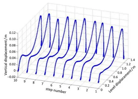
Fig.7 Space trajectory of one subject walking ten steps
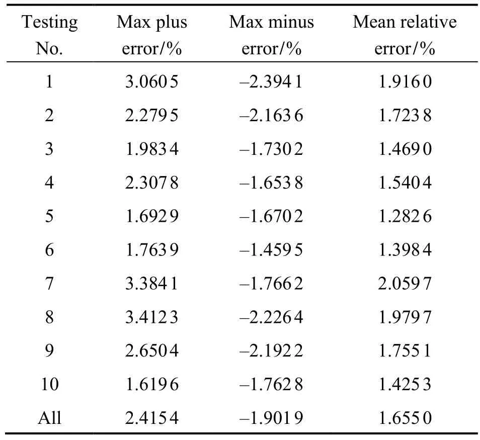
Tab.2 Results of step length calculation
To more accurately verify the practical performance of the proposed method, ten subjects were required to walk along 105.86m straight border of the football ground normally. Subjects’ toes were aligned to the start line when they were ready to walk, and subjects stopped at the end line. The absolute error and relative error of the total traversed distance together with the mean percentage of errors are shown in Table 3. It is reported that the percentage of the calculating errors over a walking distance 105.86 m is between -2.57 m (2.42%)and 2.63 m (2.48%). The mean relative errors of all testing data were below 1.80%, which was 1.9m with respect to the actual traversed distance 105.86m.
5 Conclusions
A novel step length calculation algorithm using zero velocity update and optimized double integral method for the inertial measurement device was proposed.This algorithm was developed based only on a single sensor module, consisting of a tri-axial accelerometer, a tri-axial gyroscope and a microcontroller. Experiments were conducted to verify the proposed method.
Zero velocity update was conducted as an effective method to eliminate the cumulative error of inertial sensor during the integration procedure. According to the gait feature, optimized double integral was utilized to calculate the space trajectory of per step, i.e. the step length.Experiments results verify the proposed method. The calculation error based on the proposed method was below 2.5% with respect to the actual value. In addition,the step length calculation by the proposed method was unrestricted and accurate for each subject selected, which was superior to that of previous algorithms.
[1] Liu W, Zhang Y, Yang X, et al. Pedestrian navigation using inertial sensors and altitude error correction[J].Sensor Review, 2015, 35(1): 68-75.
[2] Hediyeh H, Sayed T, Zaki M H, et al. Pedestrian gait analysis using automated computer vision techniques[J].Transportmetrica A: Transport Science, 2014, 10(3): 214-232.
[3] Yoon Y J, Li K H H, Lee J S, et al. Real-time precision pedestrian navigation solution using Inertial Navigation System and Global Positioning System[J]. Advances in Mechanical Engineering, 2015, 7(3): 1-9.
[4] Luoh L. ZigBee-based intelligent indoor positioning system soft computing[J]. Soft Computing, 2014, 18(3):443-456.
[5] Trawiński K, Alonso J M, Cordón O. Applying random linear oracles with fuzzy classifier ensembles on WiFi indoor localization problem[J]. Studies in Fuzziness &Soft Computing, 2015, 322: 277-287.
[6] Kirkup J A, Rowlands D D, Thiel D V. Dynamic tracking of a 2.4GHz waist mounted beacon for indoor basketball player positioning[J]. Procedia Engineering, 2014, 72:108-113.
[7] Harle R. A survey of indoor inertial positioning systems for pedestrians[J]. IEEE Communications Surveys &Tutorials, 2013, 15(3): 1281-1293.
[8] Tian Z, Zhang Y, Zhou M, et al. Pedestrian dead reckoning for MARG navigation using a smartphone[J].EURASIP Journal on Advances in Signal Processing,2014(1): 1-9.
[9] Zhang X X, Rong Z, Guo M F, et al. Yaw error selfobservation algorithm for pedestrian navigation via footmounted inertial navigation system[J]. Journal of Chinese Inertial Technology, 2015, 23(4): 457-466.
[10] Yuan X U, Chen X Y, Wang Y M, et al. Improved indoor pedestrian navigation method using low-cost foot-mounted AHRS and shoulder-mounted compass[J]. Journal of Chinese Inertial Technology, 2016, 24(3): 325-329.
[11] Chen G L, Fei L I, Zhang Y Z. Pedometer method based on adaptive peak detection algorithm[J]. Journal of Chinese Inertial Technology, 2015, 23(3): 315-321.陈国良, 李飞, 张言哲, 等. 一种基于自适应波峰检测的MEMS计步算法[J]. 中国惯性技术学报, 2015, 23(3):315-321.
[12] Pham D D, Suh Y S. Pedestrian navigation using footmounted inertial sensor and LIDAR[J]. Sensors, 2016, 16:120(1-17).
[13] Jahn J, Batzer U, Seitz J, et al. Comparison and evaluation of acceleration based step length estimators for handheld devices[C]//2010 International Conference on Indoor Positioning and Indoor Navigation (IPIN). 2010: 1-6.
[14] González R C, Alvarez D, Alvarez A M L J C. Ambulatory estimation of mean step length during unconstrained walking by means of COG accelerometry[J]. Computer Methods in Biomechanics and Biomedical Engineering,2009, 12(6): 721-726.
[15] Shin S H, Park C G. Adaptive step length estimation algorithm using optimal parameters and movement status awareness[J]. Medical engineering & physics, 2011, 33(9):1064-1071.
[16] Köse A, Cereatti A, Della Croce U. Bilateral step length estimation using a single inertial measurement unit attached to the pelvis[J]. Journal of Neuroengineering and Rehabilitation, 2012, 9: 9(1-10).
猜你喜欢
肇庆学院学报(2022年5期)2022-09-29
西安邮电大学学报(2022年2期)2022-09-19
包装工程(2022年10期)2022-05-27
中学生数理化·八年级物理人教版(2022年3期)2022-03-16
成都信息工程大学学报(2021年5期)2021-12-30
中学生数理化·八年级物理人教版(2021年3期)2021-07-22
西安邮电大学学报(2021年6期)2021-05-10
西安邮电大学学报(2021年5期)2021-03-14
中国惯性技术学报(2020年2期)2020-07-24
北京航空航天大学学报(2016年12期)2016-02-27