
Anti-Windup Control Strategy of Drive System for Humanoid Robot Arm Joint
2018-06-15 02:17XiaofeiZhangQinjunDuChuanmingSongandYiChengSchoolofElectricalandElectronicEngineeringShandongUniversityofTechnologyZibo255049ShandongChina
Xiaofei Zhang, Qinjun Du, Chuanming Song and Yi Cheng(School of Electrical and Electronic Engineering, Shandong University of Technology, Zibo 255049, Shandong, China)
In order to comply with the requirements of production process improvement, the severity of aging population and the special needs in military, medical, aerospace industry and so on, humanoid robot, which has the same shape as human being, can replace human to complete some work without changing human living environment. The essence of humanoid robot arm movement is that the driving motor drives the arm joint to move through the speed reduction device. Therefore, in order to ensure that humanoid robot arm can replace human’s work in various tasks, we must assure the effectiveness of the motor drive system. At present, the study on the drive system for humanoid robot arm joint mostly ignores the saturation phenomenon of the controller. However, the drive system, including the drive motor, is constrained by the volume and weight of the humanoid robot arm in practice. The output torque of the drive motor is limited[1], which results in vibration of the robot arm during working process. For example, if the load is too heavy, the drive system will become saturated when the robot is carrying heavy weights. The saturation will reduce the performance of the motion system, which could have a strong influence on the control quality of the drive system and the practical operation effect. Therefore, the saturation and limited control torque problem must be considered when the drive system for humanoid robot arm joint is designed.
Speed regulator is an important part of the motor drive system. The PI control method is generally used. Therefore, researchers proposed a variety of anti-windup control strategies based on PI control to improve the performance of the speed regulator to solve the controller saturation problem in the drive system for humanoid robot arm joint[2]. The anti-windup control strategies can be classfied into two major categories: the conditional integration method and the inverse algorithm method[3-4]. The basic idea of the conditional integration method is that the system can rapidly exit saturation by limiting integral action when the system is saturated[5]. However, the traditional conditional integration method should select different control parameters for different control objects, and the practical application is difficult. On the other hand, the inverse algorithm method takes the difference between the output value of the controller and the limit amplitude as the feedback signal of the closed-loop system to form the feedback branch. The feedback gain is determined from experience to achieve the anti-windup effect. But the feedback gain is not easy to determine, and it needs to be adjusted repeatedly to obtain the appropriate setting value[6]. So it is difficult to be used in practice. Ref.[7] proposed that the output of the PI controller is multiplied by a negative coefficient and fed back to its output to converge the output of the integral link to zero when the system is saturated. The system can break away from the saturation by this method. In Refs.[8-9], the conditional integration method was combined with the inverse algorithm method to obtain a good anti-windup effect by choosing the appropriate feedback gain. All the above schemes are the improvement of the traditional anti-windup method. But these schemes still fail to solve the overshoot problem caused by the given mutation, and lack foresight.
In order to make up for the shortcomings of the traditional anti-windup control strategy and achieve a good anti-windup effect, this paper proposes an anti-windup control strategy based on the integral state prediction. The steady state value of the integrator is predicted with this method according to the speed setting value and the load torque of the speed regulator of the drive system for humanoid robot arm joint. If the controller is not saturated, the PI controller works normally. If the controller is saturated, the PI controller stops integrating. Then the predicted steady-state value of the integrator is used as the initial input value of the integrator, which makes the PI controller achieve the effect of anti-windup. Considering that the brushless DC motor has advantages of high efficiency, simple control and less interference, this design uses a brushless DC motor as the driving motor for humanoid robot arm joint, and the direct torque control strategy is used to control a brushless DC motor. Compared with the traditional anti-windup strategy, the proposed scheme has a good anti-windup effect. The scheme can suppress overshoot, reduce the adjustment time and ensure the stability of the drive system.
1 Arm Joint Modeling
The humanoid robot arm is actuated by the control of the drive system. The reasonable design of the drive system determines the accuracy and stability of robot arm movement. The structure of the drive system for arm joint is shown in Fig.1.
The mathematical model of humanoid robot arm joint is established based on the momentum conservation of the system and the Lagrange equation[10]. Its dynamical equation is
(1)
where J is the positive definite inertia matrix of the motor, D is the positive definite inertia matrix of the robot,θris the rotor position vector of the motor,θis the connecting rod position vector of humanoid robot arm, CHis a vector containing the Coriolis force and centrifugal force, GHis the gravity torque,TLis the external interference.
The dynamical Eq.(1) is decomposed,
(2)
(3)
F=fω
(4)
(5)
where Eq.(2) is the dynamical equation of drive motor, Eq. (3) is the dynamical equation of humanoid robot, F is the friction torque of motor, FHis the friction torque of robot arm joint, f is the friction coefficient of the motor, THis a nonlinear term of robot arm, including the friction torque of robot arm joint and gravity torque,τis the control torque for joint.
During the operation of humanoid robot arm joint drive system, if the load is too heavy, the control system will be saturated because of the limited output torque of the drive motor. It will cause vibration of the arm during the motor movement. And robot arm operation performance will be affected. So it will be difficult to achieve the desired operating results. Therefore, the saturation problem of the drive system must be considered when designing the drive system for humanoid robot arm joint[11].
2 Design of Arm Joint Drive System
The arm joint driving system is the core of arm motion control. The direct torque control method is used to design the arm joint drive system in this paper, which realizes the control of the brushless DC motor and drives the robot arm movement. The direct torque control method uses the idea of space vector and stator flux orientation[12]. Through the detection of the stator voltage and current, a simple coordinate transformation is carried out to realize the calculation and observation of the stator flux and motor torque. The calculated values are compared with the given value of the flux linkage and the torque reference value outputted by the speed controller respectively. The corresponding control signals are outputted by hysteresis comparators. According to the control signal and the sector of the stator flux, the best space voltage vector is selected from the switch table to control the switching state of power tube of the inverter, and then drive the brushless DC motor to run. The system configuration of direct torque control is shown in Fig.2.

Fig.2 System configuration of direct torque control
2.1 Analysis of space voltage vector
The brushless DC motor usually works in a two-phase conduction mode, that is, only two phases are connected at the same time in the steady state. Therefore, the 6 digital method must be used to represent the switching state of the inverter power tube. Each digit represents a power tube. “1” means the power tube is on and the “0” means the power tube is off. So, effective states of the inverter are V1(100001),V2(001001),V3(011000),V4(010010),V5(000110),V6(100100). V0(000000) is a “public inverse vector”, which can reduce the torque[12]. The nonzero voltage vector and the six sector spatial distribution are shown in Fig.3.

Fig.3 Nonzero voltage vector and six sector spatial distribution
The stator voltage equation is
US=RSiS+pψS
(6)
wherepis a differential operator.
If the stator resistance is ignored, the following equation can be derived from Eq.(6),

(7)
Discretization of Eq.(7),

(8)
By Eq.(8), the stator flux speed and amplitude are related to the applied voltage vector.

Fig.4 Resolution of voltage vector
Analyzing the voltage vector with the stator flux located in the first sector, the stator flux turns counter-clockwise as an example, as shown in Fig.4. If the V1 voltage vector is applied, V1 is the carried out resolution of vector to obtain flux component. Since the direction of the flux linkage component is the same as that of the stator flux linkage, the amplitude of the stator flux linkage will increase. If the V3 voltage vector is applied and carried out resolution of vector, the direction of the V3 flux component is opposite to that of the stator flux direction, then the amplitude of the stator flux linkage will decrease. The torque is adjusted according to whether the applied voltage vector is advancing (or lagging behind) the current stator flux. If the voltage vector is ahead of the current stator flux, the torque will increase. If the voltage vector lags the current stator flux, the torque will decrease. Similarly, when the stator flux linkage is located in the other five sectors, the stator flux and torque are controlled by selecting the optimal voltage vector to get the required amplitude of the stator flux linkage and torque.
The key of direct torque control is to select the optimal voltage space vector to control the flux and torque. A space voltage vector switching table is set up by analysing the control effects of different voltage vectors, as shown in Tab.1.
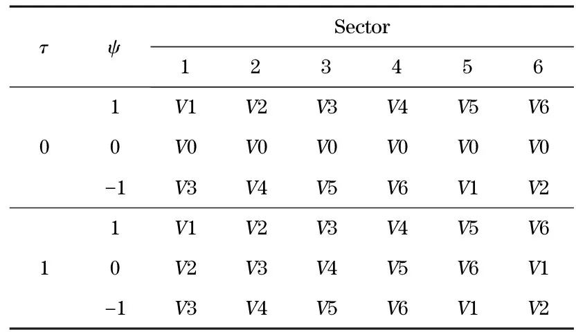
Tab.1 Switch table for direct torque control system
2.2 Stator flux linkage and torque observation
①The component of stator flux linkage in theα-βcoordinate system
(9)
whereΨsα,Ψsβ,usα,usβ,isα,isβare the components ofΨs,us,isin theα-βcoordinate system respectively.
The stator flux amplitude and angle are
(10)
(11)
② The electromagnetic torque of the brushless DC motor in theα-βcoordinate system can be described as
(12)
wherepis the pole pairs of the motor,Ψrα,Ψrβare the components of rotor flux linkage in theα-βcoordinate system respectively,θeis the rotor electric degree.
2.3 Flux linkage and torque regulation
The space voltage vector is selected according to the sector of the stator flux linkage and the deviation of the stator flux and torque.
The parameterθis the section value, and it can be determined by the position sensor;
Parameterτrepresents the trend of torqueTeincreasing or decreasing,
(13)
Parameterφrepresents the trend of stator flux linkage increasing or decreasing,
(14)
In this paper, a hysteresis comparator is used in the closed-loop of flux and torque. The stator flux and torque observation values are compared with their given values respectively, then the hysteresis comparator outputs the corresponding control signals. According to control signals and the section of stator flux linkage, the optimal space voltage vector is selected from Tab.1 to achieve the control of the motor stator flux and torque.
2.4 Analysis of speed controller model
In this paper, a brushless DC motor is used as the driving motor for the humanoid robot arm joint, and its dynamical equation is shown in Eq.(2). From Eq.(2), it can be seen that to achieve the anti-windup control for the humanoid robot arm joint and to solve the problem of limited output torque of the driving motor, the key lies in the design of the speed controller. PID control contains a differential function. Although the differential element has a predictive function, it can send out the correction signal ahead of time, but the differential action is generally small, and there is a disadvantage of amplifying the high-frequency interference signal. Moreover, due to the existence of differentials, the system cannot quickly weaken the overshoot and make the system restore stability when a sudden step occurs. Therefore, a PI controller is adopted in this paper to prevent the humanoid robot from arm vibration when a sudden change is given to a humanoid robot, a large overshoot occurs in the system, which lead to a sudden change in the torque given by the speed regulator and affect the stability of the driving system seriously during the movement[13-15]. The structure of the speed controller is shown in Fig.5.

Fig.5 Structure diagram of traditional PI speed regulation system
The PI controller equation is expressed as

(15)
whereusis the output of the PI controller,ω*is the speed reference,ωis the actual value of speed,KPis the proportional gain, andKIis the integral gain.


If |
u
s
|≤
T
max
, that is
the system is in the linear region. Conversely, the system is in the saturation zone. At this point, the output of the controller is not equal to the input of the controlled object, which makes the system unstable.
As shown in Fig.5, the speed regulator is actually a PI regulator. The speed error is calculated by the PI regulator to obtain the torque reference. Then the speed controller and direct torque control form a torque loop. Therefore, the key to design the anti-windup controller for humanoid robot arm joint drive system is how to make the drive system controller transition from a saturated zone to the linear region quickly, to avoid the sudden change of the reference having impact on the system when the system is saturated.
3 Design of Anti-Windup Controller for Arm Joint Drive System
3.1 Analysis of influence of the integral element initial value on system

F=T-TL
(16)
Take Eq.(4) into Eq.(16), we have
fω=T-TL
(17)
At this point, the output of the speed controller is
us=KPe+u
(18)
e=ω*-ω
(19)
(20)
whereuis the output of the integral.
Put Eq.(17) and Eq.(19) into Eq.(2),
(21)
The integral steady-state value of the system can be obtained by Eqs.(18)-(21),
uss=TL+fω*
(22)
whereussis the integral steady-state value of the system. By Eq.(22), it is shown that the integral steady-state value is related to the load torque and the speed reference when the system is stable.
By Eqs.(18) (21) (22), the error dynamic equation is
(23)
With the Laplace transformation on Eq.(23), we obtain
(24)

Fig.7 Structural diagram of the anti-windup controller
Eq.(24) shows that if the PI regulator parameters have been determined, the error dynamics will be determined by the initial error valuee(0), the integral steady-state valueussand the initial valueu(0). Therefore, the dynamic characteristic of the drive system for humanoid robot arm joint is related to the initial integral value of the actuator from the saturation zone into the linear region when the PI parameter is determined[16].
3.2 Design of anti-windup control strategy for humanoid robot arm joint
The traditional PI controller is represented as
us=KPe+u
(25)
The integral control method is
(26)

When the system is in the nonlinear region, that is, the PI regulator is saturated. The error dynamic equation is
(27)
uss=TL+fω*
(28)
As a result, the integral state prediction of the PI controller in the saturated state is estimated as
(29)


Fig.8 Structural diagram of the anti-windup control system for humanoid robot arm joint
4 Simulation and Analysis
In order to verify the effectiveness of the anti-windup controller for the humanoid robot arm joint based on the integral state prediction, this paper uses MATLAB/SIMULINK to build a model for simulation verification.
Brushless DC motor parameters are specified as follows: the rated voltage is 12 V, the rated power is 24 W, the armature resistance is 24 Ω, the moment of inertia is 0.005 kg·m2, the rated speed is 1 800 r/min, the damping coefficient is 0.000 2 N·m·s/rad, the pole of motor is 4 pairs, the difference between the self-inductance and mutual-inductance of stator windings isL-M=2.5 mH.
In the simulation process, the motor starts with no load, the given speed of the motor is set to 1 800 r/min, the stator flux amplitude is 0.8 Wb, the speed PI controller parameters are set toKP=1.2,KI=0.2. The load torqueTL=0.2 N·m applied at 0.4 s. The control effect of anti-windup control strategy for the humanoid robot arm joint based on the integral state prediction is observed by simulation.
Fig.9 is the stator flux trajectory, the speed and torque waveforms are shown in Fig.10 and Fig.11, respectively. Fig.11a shows the torque changing curve at no load. Fig.11b shows the torque response when the load varies from 0 N·m to 0.2 N·m at 0.4 s. Fig.12 is the Back-electromotive force waveform of the brushless DC motor.

Fig.9 Stator flux linkage
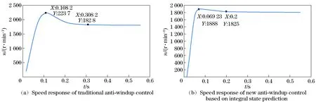
Fig.10 Speed graph

Fig.11 Torque graph

Fig.12 Back-electromotive force of brushless DC motor
Taking ±2% as the error band, and the initial speed is given as 1 800 r/min. As shown in Fig.10a, the peak speed reaches 2 237 r/min at 0.108 2 s with the traditional anti-windup control method. The speed reaches 1 826 r/min at 0.308 2 s, the speed is within the allowable error range, and the speed is stable. The overshoot is 24.3% and the adjusting time is 0.308 2 s. The peak speed reaches 1 888 r/min at 0.069 23 s with the anti-windup control method based on the integral state prediction and the speed reaches 1 825 r/min at 0.2 s, as shown in Fig.10b, the speed reaches a stable range. The overshoot is 4.8% and the adjusting time is 0.2 s. As shown in Fig.12, the top of the Back-electromotive force waveform of the brushless DC motor is fluctuated in the range of 6±0.12 V, and the motor output power can be regarded as constant, so the vibration of the torque is reduced. By comparing the simulation curves of the traditional anti-windup method with the simulation curves of the new anti-windup control method based on the integral state prediction, it is obvious that the new anti-windup controller based on the integral state prediction can effectively suppress the overshoot of the system. And the new anti-windup controller can reduce the adjusting time, achieve the purpose of anti-windup.
5 Conclusion
This paper presents an anti-windup control strategy for a humanoid robot arm joint based on the integral state prediction, which solves the problem caused by the drive motor limited output torque and the saturation of the drive system. The traditional anti-windup strategy and the new anti-windup strategy are both analyzed in theory. This new control strategy not only inherits the advantages of simple structure and good robustness of the traditional anti-windup method, but also compensates for the shortcomings of the traditional anti-windup method. The simulation results show that the new control strategy has a good anti-windup effect and can reduce the adjusting time and the overshoot of the system effectively. The new strategy also speeds up the response, improves the stability of the system, suppresses the vibration phenomenon of the robot arm and ensures that the system has a good dynamic performance.
[1] Xie Limin, Chen Li. Robust fuzzy sliding mode control of free-floating space robot with flexible-joints and bounded torques[J]. Engineering Mechanics, 2013, 30(8): 298-304.(in Chinese)
[2] Dong Xijun, Yao Yu, Wang Zicai. Anti-windup design based on filter and its application to servo system[J]. Journal of Harbin Institute of Technology, 2002, 32(1): 101-104. (in Chinese)
[3] Yu Yanjun, Chai Feng, Gao Hongwei, et al. Design of PMSM system based on anti-windup controller[J]. Transactions of China Electrotechnical Society, 2009, 24(4): 66-70.(in Chinese)
[4] Zhang Xinghua, Nie Jing, Wang Deming. Variable structure anti-windup controller for direct torque controlled induction motor drives[J]. Electric Machines and Control, 2013, 17(1): 77-81. (in Chinese)
[5] Qi Liang, Jia Tinggang, Shi Hongbo. Design of permanent magnet synchronous motor speed controller based on anti-windup[J]. Electric Machines and Control Application, 2011, 38(9): 17-20. (in Chinese)
[6] Zhang Xinghua, Yao Dan. Anti-windup speed controller design for direct torque controlled induction motor drives[J]. Transactions of China Electrotechnical Society, 2014, 29(5): 181-188. (in Chinese)
[7] Miao Jingli, Li Qimeng. The new anti-windup PI controller in the application of the induction motor DTC system[J]. Small and Special Electrical Machines, 2013, 41(12): 47-50. (in Chinese)
[8] Yang Ming, Xu Dianguo, Gui Xianguo. Study of AC PMSM speed servo system anti-windup design[J]. Proceedings of the CSEE, 2007, 27(15): 28-32. (in Chinese)
[9] Jordi Espina, Antoni Arias. Speed anti-windup PI strategies review for field oriented control of permanent magnet synchronous machine[J]. Power Electronics Controllers for Power Systems, 2009: 279-285.
[10] Wang Liangyong, Yang Xiao. Trajectory tracking control for robot manipulators endowed with feedforward and neural networks[J]. Electric Machines and Control, 2013, 17 (8): 113-118. (in Chinese)
[11] Phil March, Mattewc Turner. Anti-windup compensator designs for nonsalient permanent magnet synchronous motor speed regulators[J]. IEEE Transactions on Industry Applications, 2009, 45(5): 1598-1606.
[12] Hu Yuwen, Gao Jin, Yang Jianfei, et al. Direct torque control system of permanent magnet synchronous motor[M]. Beijing: China Machine Press, 2015. (in Chinese)
[13] Hu Yongjin, Huang Xianlin, Yin Hang, et al. Design of controller for a target simulator based on optimal anti-windup theory[C]// Proceedings of the 25th Chinese Control Conference, Harbin, China, 2006: 1569-1572.
[14] Yang Ming, Xu Dianguo, Gui Xianguo. Review of control system anti-windup design[J]. Electric Machines and Control, 2006, 10(6): 622-626. (in Chinese)
[15] Visioli A. Modified anti-windup scheme for PID controllers [J]. IEEE Control Theory and Applications, 2003, 150(1): 49-54.
[16] Niu Li, Yang Ming, Tang Siyu, et al. Design of anti-windup PID controller with integral state prediction[J]. Transactions of China Electrotechnical Society, 2014, 29(9): 145-152. (in Chinese)
 Journal of Beijing Institute of Technology2018年2期
- Journal of Beijing Institute of Technology的其它文章
- Two-Dimensional Direction Finding via Sequential Sparse Representations
- Curvature Compensated CMOS Bandgap Reference with Novel Process Variation Calibration Technique
- Energy Optimization Oriented Three-Way Clustering Algorithm for Cloud Tasks
- Different Frequency Synchronization Theory and Its Frequency Measurement Practice Teaching Innovation Based on Lissajous Figure Method
- Multi-Object Tracking Based on Segmentation and Collision Avoidance
- Super-Resolution Image Reconstruction Based on an Improved Maximum a Posteriori Algorithm