
Robust adaptive fault-tolerant control of a tandem coaxial ducted fan aircraft with actuator saturation
2018-06-28 11:05XiolingWANGChngleXIANGHomyounNAJJARANBinXU
CHINESE JOURNAL OF AERONAUTICS 2018年6期
Xioling WANG,Chngle XIANG,Homyoun NAJJARAN,Bin XU
aVehicle Research Center,School of Mechanical Engineering,Beijing Institute of Technology,Beijing 100081,China
bOkanagan School of Engineering,The University of British Columbia,Kelowna V1V 1V7,Canada
1.Introduction
The ducted fan aircraft,as a novel aircraft design,is driving evident research interest in academic and industrial communities.Since 1990s,many countries have started research in this field one after another,and have developed different ducted aerial aircrafts.1Compared with traditional flight aircrafts,the ducted fan aircraft has special characteristics that enable it to complete various applications on areas that are unknown,dangerous,and inaccessible to traditional aircrafts.The protected rotor blades of the ducted fan aircrafts are compatible with the environments potentially cluttered with obstacles.Moreover,a ducted fan produces more thrust than an open rotor at the same blade size.These features also ensure a markedly compact body design with strong mobility,low noise,and high efficiency.2,3
In Beijing Institute of Technology(BIT),several prototypes of the ducted fan aircraft have been designed for research on modelling,system identification and flight control algorithms.2,4,5The design iterations of the ducted fan aircraft inBIT is shown in Fig.1.However,for the first two prototypes,they have proved to reveal poor stability and controllability due to structural coupling.4Under this context,as shown in Fig.2,the latest prototype adopts two ducts with coaxial rotors and control vanes.In order to illustrate the features of the new design,the moment generation mechanism of these prototypes is given in Table 1.For the latest model,pitch and yaw moment are generated by changing the speed of the four rotors.To be specific,roll moment is regulated by the control vanes.Compared to the previous ones,this newly adopted structure is able to provide more control moments with the same size duct,especially in roll direction.On that case,the new aircraft is expected to achieve better decoupling features and controllability.
In order to achieve various types of civil and military applications,the novel ducted fan aircraft must have the strong ability for trajectory tracking independent of the atmospheric conditions.A number of approaches to flight control of novel ducted fan aircraft and other UAVs have been applied to a variety of problems.For example,as a classic control method,PID controller is used by Sheng and Sun,6but it is not robust to noise and disturbance,and therefore fails to ensure performance for full envelop flight.Dynamic inversion control and sliding mode control are also presented.7,8Although these control algorithms are able to reject external disturbance and achieve good control performance in simulations,they rely on known and accurate system model.Neural Network(NN)techniques also have been widely employed for robots in literatures.He et al.9applies an NN controller to suppress the vibration of a flexible robotic manipulator system with input deadzone.Although input deadzone and unknown dynamics can be approximated,the method does not consider large disturbance and is just validated by Single Input Single Output(SISO)system.Adaptive NN10and adaptive fuzzy NN11are used to identify system uncertainties and disturbance for a constrained robot.However,their methods are of great complexity and difficult to utilized in practical engineering.In consideration of model errors,H-infinity control and adaptive control are widely adopted.Successive two-loop control architecture5is employed and control gains are well tuned by Non-smooth optimization method.This control structure ensures robust stabilization,but transient tracking performance drops when large uncertainty are included.Indirect adaptive control schemes 6 and adaptive gain scheduling algorithm12are respectively adopted to deal with parametric uncertainty.These adaptive control methods guaranteed small tracking error and the convergence of adjustable parameters.However,the dynamics is over simplified and dynamic couplings is not considered.Standard Model Reference Adaptive Control(MRAC)framework13is proposed to cope with system uncertainty and also guarantees that the tracking error decreases asymptotically to zero.Unfortunately,the previous research does not take mismatched disturbance into consideration.
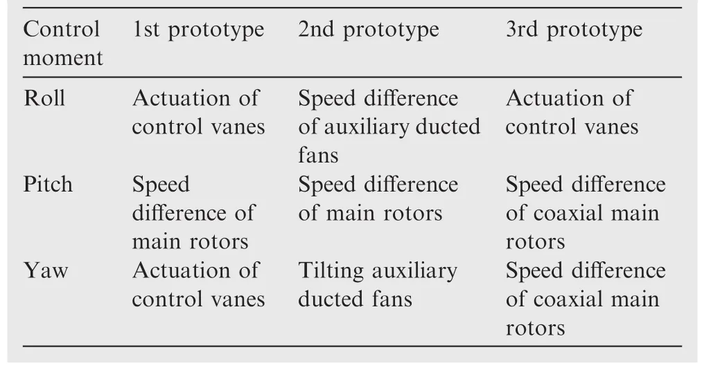
Table 1 Moments generation mechanism of ducted fan aircrafts in BIT.
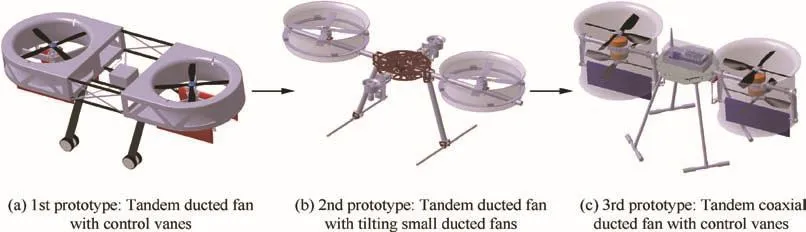
Fig.1 Design iterations of ducted fan aircrafts in BIT.
On the other hand,an important problem encountered in practice is actuator saturation because it is frequently one of the main sources of instability,degradation of system performance,and parasitic equilibrium points of a control system.14Some solutions have been provided to handle input constraint for flight control system.Based on structured H-infinity optimization,an anti-windup compensator15is designed to preserve stability and maintain the performance level under input saturations.Guaranteed transient performance based attitude control with input saturation is also proposed using the backstepping method.16Nevertheless,these methods cannot ensure control performance in the presence of large mismatched disturbance and system uncertainty.Auxiliary system17,18that is embedded to Lyapunov function is also adopted to deal with input saturation.Nevertheless,the effect of the auxiliary system parameters on system performance is implicit,which could result in a very conservative design.Zhang et al.19adopts robust Model Predictive Control(MPC)algorithms that transforms the design problem into a minimization problem of a worst-case performance index with respect to model uncertainty.However,the designed controller is too conservative to achieve fast tracking and high bandwidth.
In addition to flight control aspects,property of controllability that relates to the mechanical design is equally important in practice.Skogestad and Postlethwaite20have proved that input–output controllability is independent of controller.This property,related to its mechanical structure of the real plant,is able to show inherent limitations on system control and the ability to reject external disturbance.Thus we will start with a comprehensive controllability analysis to provide insightful suggestions for mechanical design.In this study,robust adaptive fault-tolerant tracking control is presented for the novel ducted fan aircraft.The proposed method bene fits techniques of H-infinity control and adaptive control.Considering mismatched disturbance,the baseline controller tuning is completed by non-smooth optimization algorithm21in structured H-infinity synthesis,which provides reference dynamics for adaptive control.Motivated by the classic MRAC algorithm22–24,the adaptive control augmentation is then applied to recover the desired performance in the presence of system uncertainty,mismatched disturbance and actuator fault.Further,the reference model modification in consideration of transient response and actuator saturation is then performed to improve robustness and tracking accuracy.
The remaining part of the paper is organized as follows:system model and comprehensive controllability analysis are first presented in Section 2;Robust H-infinity synthesis for baseline controller is proposed in Section 3;Section 4 details the design of augmented adaptive control law;and finally,we draw concluding remarks in Section 5.
2.System model and comprehensive controllability analysis
2.1.Model description
Modelling of ducted fan dynamics is one the popular topics in the literature of unmanned aircrafts.Based on aerodynamics of open rotors,Johnson and Turbe25proposes a modified momentum model by an in flow theory.In some researches4,26,duct effect is simply represented by in flow deflection and thrust augmentation due to the suction flow of the lip.However,regarding duct with coaxial rotors,the dynamics is much more complicated than duct with single rotor.3Based on our results of Computational Fluid Dynamics(CFD)that is shown in Fig.3,the duct generates almost half of the total thrust,and the lower rotor produces more lift than the upper counterpart,which challenges the conclusions by Ohanian1and Jang et al.27Therefore,it is very difficult to capture complete dynamics of duct fan with coaxial rotors by mechanism modeling.In this work,instead of complex nonlinear model with a number of unknown parameters,we adopt a simple control-oriented model.
Thus,system state vector xp∈Rnpand control input u∈Rnare defined as
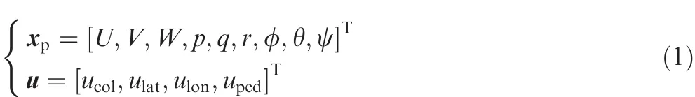
where[U,V,W]Trepresents body-axis velocity,[p,q,r]Tand[φ,θ,ψ]Tare respectively Euler angular rate and angle.u is input vector and each of its components is normalized to[-1,1].The normalization of input vector is very important.First,the normalized input helps the elements of control matrix to keep at a proper scale,and avoid control matrix to be ill conditioned.Second,this normalization also ensures similar scale for the components of transfer function matrix of the closed-loop system,which is necessary to H-infinity framework on system tuning.
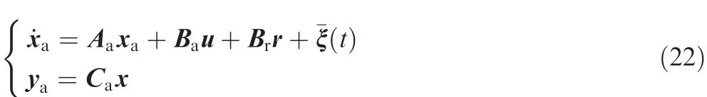
Linearized at trimming points,the uncertain system model22is
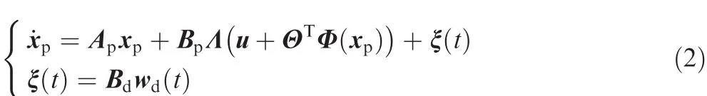
where Apand Bpare respectively system state matrix and control matrix.The matched system uncertainty is represented by ΘTΦ(xp). Θ is real matrix,and Φ(xp)is the known N-dimensional repressor vector whose components are locally Lipschitz-continuous functions of xp.This matched uncertainty is introduced to consider unmolded dynamics and model errors.Λ denotes actuator fault that could be uncertain control gains or incorrectly estimated the system control effectiveness.13
The system is also under a uniformly bounded time dependent disturbance ξmax, which is mismatched disturbance,22

where wd(t)is related to unknown moments and forces,ξmaxis the bound of mismatched disturbance,and||·||denotes H-infinity norm of vector.In this way,the disturbance vector and the parameter matrix are as follows

where dU,dV,dw,dp,dq,drare respectively disturbance for state U,V,W,p,q and r.
In order to obtain nominal system matrix Apand Bp,closed-loop flight tests have been performed in hovering condition.We followed standard steps for system identification,28,29which will not be detailed in this paper.The identification results are as follows
Then comprehensive controllability gain is proposed as follows:
System input u is rewritten as the sum of bases for each control channel,

2.2.Comprehensive controllability analysis with mismatched uncertainty
Controllability is an important property of a control system and plays a crucial role in many control problems,in terms of evaluation of system controllability,a classic way is to compute the controllability matrix30

It is easy to verify that our nominal system(Ap,Bp)is controllable.Nevertheless,the system that achieves classic controllability often disregards the quality of the response between and after these states,and the magnitude of required inputs may be excessive.5In that case,motivated by Singular Value Decomposition(SVD),31we propose an alternative solution that enables to quantify actual ease of system control in frequency-domain,which is called comprehensive controllability analysis.
Since we focus on nominal system with external disturbance(mismatched disturbance),matched system uncertainty and actuator fault are ignored.In this way,system model is then released to

We first factorize the nominal system into a standard SVD,

where Umand Vmare respectively output matrix and input matrix,S is singular value matrix,(·)Hdenotes conjugate transpose.These corresponding matrices are given as follows
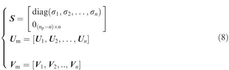
where diag(·)denotes diagnose matrix,and σ denotes singular value.
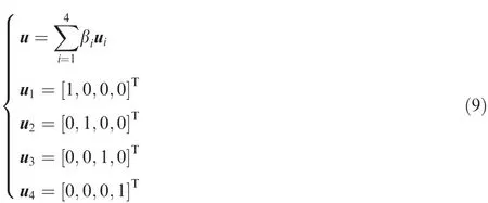
where βiis the coefficient of components of the input vector u,and uiis the base for each control channel.For the sake of input normalization,we have

The comprehensive controllability gain is defined as

where ω is frequency.
Through SVD,system input u is rotated by input matrix Vm,and the rotated input u*can be represented by the new bases

where θiis denotes the coefficient of components of rotated input vector u*and Vmis output matrix for SVD.
According to property of matrix norm,since the input matrix||Vm||=1,we have

where||·||maxdenotes maximum H-infinity.
An essential property of SVD is
where Uiand Viare respectively components of output matrix Umand input matrix Vmin Eq.(8).
In this way,the gain is deduced by
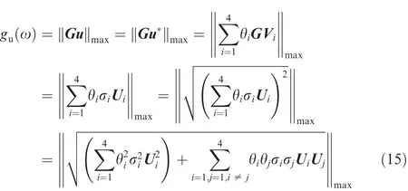
Since Umis orthogonal matrix,then

Therefore,the comprehensive controllability gain is calculated by

It is shown in Fig.4 that comprehensive controllability gain of most states in low frequency are more than 1,indicating that controllability for those states is excellent.Unfortunately,roll channel is difficult to control due to the low controllability gain in roll angle and roll angular rate,which also means that robust stability margin of roll channel is fundamentally small for closed-loop system.
Eq.(17)provides the maximum gain from system input to all states in frequency domain.Similarly,it is easy to calculate the maximum gain from mismatched disturbance to system output,and the disturbance system is defined by

Then we get a solution to estimate the maximum tolerance of mismatched disturbance for the linear model.The gain generated by disturbance should be compensated by system input,so we have the following constraints

where gd(ω)denotes comprehensive controllability gain for mismatched disturbance and kmdenotes maximum disturbance tolerance.Note that we just focus on states that follow the reference command,i.e.U,V,W,and ψ.
The reason why the inner-loop states(φ,θ,p,q,and r)are removed is that these states will deviate from trimming to compensate disturbance.In terms of our nominal system,the calculated maximum disturbance tolerance is km=2.1055,indicating that the nominal system is able to attenuate disturbance that is less than 2.1055 times as unit disturbance in each direction.Corresponding controllability gains are plotted in Fig.5.It is shown that the disturbance makes the greatest influence on yaw angle ψ in low frequency,because yaw channel have already reached the maximum tolerant magnitude rather than other states.In other words,the system has to make large control effort in yaw channel(uped)to deal with disturbance.Hence,there is low margin for disturbance rejection in yaw channel for our new designed aircraft.
3.Robust H-infinity synthesis for baseline controller
In this work,we will present rigorous steps for robust adaptive fault tolerant control of our novel ducted fan aircraft.This control problem is divided into two sub-problems:robust baseline control design and the adaptive augmentation,each with its own design objective.The first step,i.e.robust baseline control,is presented in this section.
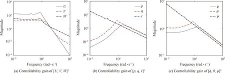
Fig.4 Comprehensive controllability gain of each state for nominal system.

Fig.5 Comprehensive controllability gain for nominal system with maximum tolerance of mismatched disturbance.
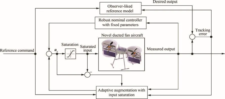
Fig.6 Robust adaptive flight control configuration.
3.1.Structured baseline controller design via Non-smooth optimization
As shown in Fig.6,the reference model represents the baseline closed-loop dynamics that would be achieved under the baseline controller and without any uncertainty and actuator fault.22Then this desired dynamics is expected to be followed by actual response through the adaptive control law when uncertainty and actuator fault are included.Therefore,it is necessary to find robust control structure for baseline control that asymptotically rejects mismatched disturbance and track reference commands accurately with constrained control input.The adopted baseline control configuration is plotted in Fig.7.The inner loop,in degrees for static state feedback control,is responsible for stabilization and decoupling,and the outer loop with integral feedback connections is applied to provide the desired command-tracking performance.
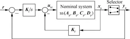
Fig.7 Baseline control configuration.
The system output tracking error is

where r=[Uref,Vref,Wref,ψref]Tis reference command,and y=[U,V,W,ψ]Tis system output.
Then the system states xpis augmented with integrated output tracking error

where xais the augmented state vector.
The open-loop dynamics including mismatched disturbance(Eq.(6))is extended to
where corresponding matrices are as follows
燃烧炉内生成的有机硫是硫磺回收装置有机硫的主要来源,而常用控制方案是将其在一级克劳斯反应器内最大限度地水解生成H 2 S,残余有机硫在尾气处理单元加氢水解反应器中进行转化。在硫磺回收单元各级反应器中,通常一级反应器床层温度为280~360℃,后续各级反应器床层温度略低于此值,而现有工业催化剂性能存在局限性,在较低的反应温度下对有机硫的水解催化性能均较差。尾气处理单元加氢水解反应器床层温度往往在240~330℃,可实现一定的末级催化加氢水解作用,现有主流尾气处理工艺对加氢反应器后的残余有机硫几乎不再进行更深度的转化,将直接被带入灼烧炉燃烧转化为SO2后,通过烟囱排入大气。

Then the baseline control for the extended open-loop systems is written as

where the controller parameters matrix is


Fig.8 General interconnection for H-infinity synthesis.
The static gain matrix for controller indicates ease practical testing,validation,and possibly on-site re-tuning.5In terms of tuning methods, Linear Quadric Regulation (LQR)method13,23is applied to tune the baseline controller gain Kx.Although the controller tuned by LQR method achieves ideal tracking performance for step-input commands,it ignores mismatched disturbance and input energy limitations.Therefore,a general H-infinity synthesis is adopted in Fig.8,and P(s)is integrated system model.
Then the considered controller parameter tuning is to solve the following optimization problem:

where Ti(Kx)denotes that target function regarding specifications such as tracking accuracy,input energy limitations and disturbance attenuation.Since the H-infinity synthesis problem is no longer convex for structural constraints,we use the non-smooth approach21to tune the proposed controller in Eq.(25).
In order to satisfy accurate command tracking with limited amplitude of control input,we address that
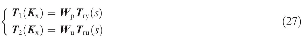
where Try(s)and Tru(s)respectively denote the closed-loop transfer function from reference command to system output and control input.H-infinity norm of closed transfer function Tru(s)is applied as the measurement of control energy.Wpand Wuare corresponding weighting functions.
Obviously,the parameters of weighting function make a great influence on the tuning results.Through selections of different weighting functions,closed-loop system bandwidth of each channel versus control energy is given in Fig.9.Generally,the tracking bandwidth is conflicted with control input limitations under unit reference command,since high input energy is required to ensure a rapid response.Hence,we have to limit control energy by specifying an appropriate desired bandwidth in order to avoid large control effort that possibly leads to input saturation.
In addition to Eq.(27),another target function is addressed for disturbance rejection,which is written as

where Tdy(s)denotes the closed-loop transfer function from mismatched disturbance to system output and Wdis weighting function.

Fig.9 Closed-loop system bandwidth of each channel versus‖Tru(s)‖∞ (control energy).
Obviously,a small magnitude of||Tdy(s)||is expected to attenuate mismatched disturbance.Therefore,the complete non-smooth H-infinity synthesis including Eqs.(27)and(28)are performed to ensure a good trade off among specifications on tracking,control effort limitation,and disturbance rejection.
After some repetitions,the selected weighting functions and the optimized gains are as follows

Fig.10 shows that singular value plots of Try(s),Tdy(s)and Tru(s)that respectively demonstrates the archived tracking performance,the ability to disturbance rejection and the constrained control energy of the resulted closed-loop system.Therefore,the performance of closed-loop system is validated in frequency domain.The next step is the corresponding simulation in time domain.
3.2.Simulation of the novel ducted fan aircraft under mismatched disturbance
The disturbance d(t)stands for external forces and moments,where the components are described by Dryden model.32The disturbance is constructed by filtered Gaussian white noise n(t)with zero mean

where Gf(s)is a low-pass filter with bandwidth ωf,and we have

The Power Spectral Density(PSD)of n(t)is given as n0,then we have the approximated power of the filtered signal

Then the standard deviation of the filtered signal is

In this work,we choose a low-pass filter with bandwidth at ωf=2.5 rad/s and the standard deviation of each disturbance channel is 0.4,as shown in Fig.11.To verify the effectiveness of the tuned controller,simulation results for the close-loop system under mismatched disturbance are plotted in Figs.12 and 13.
Fig.12 reveals that the closed-loop system achieves to track reference command in a rapid speed and small tracking error.Clearly the closed-loop system is able to maintain its command tracking abilities in the presence of mismatched disturbance.

Fig.10 Singular value plots of Try(s),Tdy(s)and Tru(s).

Fig.11 Mismatched disturbance for simulation.

Fig.12 System outputs of reference tracking response under mismatched disturbance.
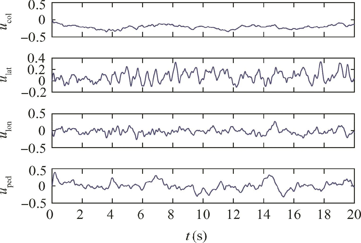
Fig.13 Control inputs of reference tracking response under mismatched disturbance.
As plotted in Fig.13,the amplitude of control inputs is constrained within[-0.5,0.5],since target function Eq.(27)for control energy limitation is applied.It is interesting that the largest control effort is the pedal input(uped)that primarily produces yaw moment.Therefore,there is less margin in yaw direction to compensate disturbance than other channels.
4.Adaptive control design considering system uncertainty,actuator fault and input saturation
Although the baseline controller designed by robust H-infinity synthesis is able to achieve satisfactory performance in the presence of mismatched disturbance,the robust performance cannot be ensured under large system uncertainty and actuator fault.22In addition,the proposed H-infinity synthesis neglects the occurrence of input saturation.In this section,as shown in Fig.6,the adaptive augmentation of the baseline controller will be designed to recover the desired performance under system uncertainty,actuator fault and even when input saturation is active.
4.1.Adaptive control law with improved transient response and robustness
Similar to Eq.(22),the open-loop system with uncertainty and actuator fault is extended as

The state tracking error e=xa-xris used to drive the composite adaptive control input

where uadis adaptive augmentation for the baseline control ubl.
Then we have the following equations with redefined regressive vector Φa(ubl,xp)
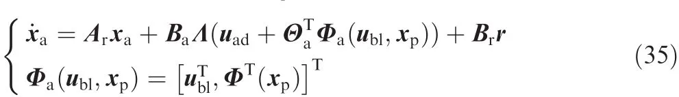
The extended uncertainty matrix is

The reference dynamics to be followed is written as
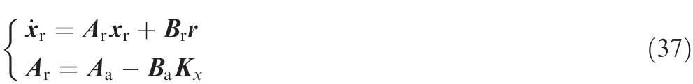
Note that the reference model is the nominal closed-loop system stabilized by baseline controller.In order to improve the transient characteristics of the closed-loop dynamics,the observer-like reference model13is written as

where Keis the error feedback gain.
The adaptive control input is calculated by estimated uncertainty.and Φa(ubl,xp)

which is substituted to Eq.(35)to give

Then the equation for tracking error is deduced as

The error feedback gain is given as the following Algebraic Riccati Equation(ARE)22
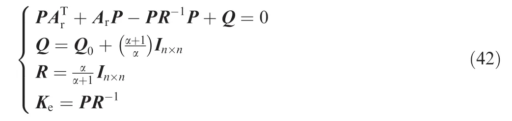
where Q0and α are tuning parameters.
The observer closed-loop matrix is

Substitute it to Eq.(42),we have
The adaptive control laws with adaption rate Γais selected as

In order to perform stability analysis,we choose the Lyapunov function candidate

Then we have

Eq.(47)indicates that the state tracking error e is uniformly bounded in time.In addition,the second derivative of V(e,ΔΘa)is written as

Note the second time derivative of the Lyapunov function is also uniformly bounded,which yields that the system is globally asymptotically stable by Barbalat’s lemma13and the state tracking error satisfies limt→∞‖e(t)‖ =0.
To perform transient dynamics analysis,Eq.(41)is rewritten as
Then we have the asymptotic relation22that defines the corresponding convergence rate

where O denotes Bachmann–Landau asymptotic order notation.33
If we set a constant positive definite symmetric matrix P0,we can deduce

The Eq.(51)can be viewed as singularly perturbed system,where α is a small parameter.In this case,we can claim that for a sufficiently small α > 0,while starting from an initial time t0,this singular perturbation system has a unique solution e(t,α)on an in finite interva.22Then we have the following conclusion about system state13,22
where o(1)is a function of time with limt→∞o(1)=0,and O(1)decays to zero no slower than α.
Eq.(52)indicates that quantifiable transient characteristics of the closed-loop tracking performance can be ensured using sufficiently small parameter α,so as to reduce oscillations in the adaptive control system.12
Note that the proposed control law only considers matched uncertainty.Although the mismatched disturbance has been sufficiently discussed and rejected by the nominal baseline controller for the reference dynamics,we still need to make some modifications to achieve a more robust result.In this work,dead-zone modification and projection operator12are combined as the robustness modifications to Eq.(45)

where μ(||e||)represents dead-zone modification,which prevents adaptive parameters from drifting away due to noise,system uncertainty and external disturbance.31And proj()denotes projection operator which is defined as

where β,Γ,and x are projection variables,▽ denotes gradient operator,βmaxand ε are tuned parameters.
The adaptive control law modified by projection operator will force the tracking error to become small by preventing the adaptive parameters evolving out of the preset bounds.It also helps to avoid undesirable windup phenomenon for nonlinear integrators.
4.2.Adaptive control law modification for input saturation
The ability to deal with input saturation is one of the fundamental problems for practical applications,especially along with disturbance and actuator fault.The saturation function is defined as

where b is the allowable bound of the saturated variable x.This saturation function is imposed on each component of control input,and the difference vector between designed input and the saturated input is calculated as
In this work,motivated by dynamic anti-windup compensators,34the reference model is modified to adapt intensity of the saturation by reducing magnitude of reference signal during the transient process.In that case,the reference model(Eq.(38))is evolved to

Similar to those steps in Section 4.1,we have the following error dynamics
Choose the Lyapunov function candidate
If we apply the modified adaptive control law for input saturation

where Γuis adaption rate for input saturation.
The time derivative of V(e,ΔΘa,ΔKu)can be computed as

Therefore,global asymptotic tracking is proved for the proposed system in the presence of input saturations.In particular,we also use projection operator to limit adaptive gain Kuto avoid integrator windup problems,which is represented by Due to feedback term KuΔu that is attached to the proposed reference model,the reference command is reduced to compensate saturations,as the cost of delayed transient response.

4.3.Numerical simulation of the novel ducted fan aircraft

Fig.14 Evaluation model of the novel ducted fan aircraft.
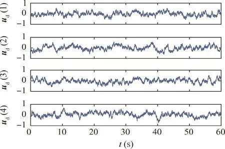
Fig.15 Matched system uncertainty for simulation of novel ducted fan aircraft.
In previous sections,rigorous design steps for robust adaptive control have been detailed.In order to evaluate the effectiveness of the proposed algorithm,a series of simulations are performed on our novel ducted fan aircraft.System parameters are taken from the results in Section 2.1.In the simulation,evaluation model includes system uncertainty,mismatched disturbance and actuator fault,as shown in Fig.14.The uncertain system is written as

In terms of mismatched disturbance,we adopt the same signal(see Fig.11)in Section 3.2.Λ is set to 0.75 to account for 25%loss of effectiveness that regards to actuator fault.The matched system uncertainty is denoted by ud,which is also approximated by filtered Gaussian white noise(Eq.(29))and given in Fig.15.The corresponding parameters of udis

where ωf(·)and σ(·)respectively denotes standard deviation and bandwidth.
In our adaptive control law,the term ΘTΦ(xp)is used to estimate the system uncertainty ud,and as for simplicity,we adopt the following regressive function
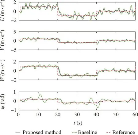
Fig.16 System outputs of reference tracking response by baseline control and adaptive control(no input saturation).

Fig.17 System outputs of reference tracking response by proposed method and MARC-LQR method(no input saturation).

The other parameters of adaptive control law are given as Q0=80I13×13, α =0.1, Γa=5I13×13, Γu=-2.9I4×4
And the maximum allowable bound for the projection operator is set to 2.
In the first simulation,we will validate the performance of the proposed adaptive method with no input saturation.Fig.16 provides reference tracking response of the ducted fan aircraft by baseline control and adaptive control.Section 3.2 shows that the baseline controller enables nominal system to achieve satisfied performance.However,when matched uncertainty and actuator fault is included,the robust baseline controller alone reveals large tracking error,whereas the adaptive controller keeps good performance.Therefore,the advantage of the adaptive augmentation over the baseline controller is verified.
In terms of baseline control tuning,(LQR)13,22,23method has been applied by classic MRAC method.It is pointed out that one short of LQR method is the ignorance of mismatched disturbance,which has been considered by our algorithm.Reference tracking response conducted by the proposed method and its comparison are plotted in Fig.17.Compared to classic MRAC-LQR algorithm,the proposed method enables a faster tracking speed and smaller fluctuation,especially for yaw channel.This progress of system performance is attributed to the adoption of H-infinity synthesis for baseline control,and observer-like reference model for its adaptive augmentation.The reason for the existence of tracking error is that the closed-loop system is under continuous matched uncertainty and mismatched disturbance at very large magnitude(see Figs.11 and 15).In addition,the control effort to attenuate these uncertainty and disturbance and the bandwidth of actuators are limited.Therefore,the tracking error cannot be extremely small.

Fig.18 System outputs of reference tracking response by the proposed method and MARC-LQR method (with input saturation).

Fig.19 Control input of reference tracking response by proposed method and MARC-LQR method (with input saturation).
In the next simulation,we will test performance of closed-loop system with the activated actuator saturation.The allowable bound of control input is 0.5 for each control channel,which is very serious saturation.The corresponding reference tracking response and control input are respectively plotted in Figs.18 and 19.We can observe that the classic MRAC-LQR controller fails to maintain stability,while the proposed method still provides satisfied response in the transient phase.Note that tracking performance is unavoidable degraded,because in the proposed reference model(Eq.(57)),the reference command is reduced to compensate the saturated control input,indicating that system response is delayed.
5.Conclusions
This study presents a robust adaptive control of novel tandem coaxial ducted fan aircraft.The comprehensive controllability analysis provides a detailed assessment of the controllability of the prototype as well as the margin to reject mismatched disturbance.In this way,the primary challenge for the flight control design is attributed to poor controllability in roll direction,and low margin for disturbance rejection in yaw direction.Based on the control-oriented model,a control framework combining robust baseline controller and its adaptive augmentation is proposed.Mismatched disturbance attenuation is ensured by the robust baseline controller tuned by H-infinity synthesis.To deal with system uncertainty,actuator fault and input saturation,the adaptive augmentation of the baseline control is applied.In order to illustrate the superiority of the proposed method,we compare our results with those classic MRAC methods13,22,23by numerical simulation.The simulation results showed that,for system uncertainty,mismatched disturbance and actuator fault,the proposed algorithm achieves the closed-loop system better transient response and more robust margin than the classic MRAC method.Especially when input saturation is activated,the proposed method provides slightly degraded performance whereas the classic MARC method deteriorates to be instable.
There is still certain margin to improve the proposed method in near future.For instance,systematic methodology to select parameters(Q0,α,Γa,and Γu)for the adaptive control can be researched to achieve better system performance.In addition,simulation on nonlinear model or real flights should be performed to further validate the proposed algorithms.Another possible research topic could be robust control considering time delay or bandwidth limitation of actuators.
1.Ko A,Ohanian O,Gelhausen P.Ducted fan UAV modeling and simulation in preliminary design.AIAA modeling and simulation technologies conference and exhibit;2007 Aug 20–23;Hilton Head.Reston:AIAA;2007.p.1–10.
2.Wang Z,Liu Z,Fan N,Guo M.Flight dynamics modeling of a small ducted fan aerial vehicle based on parameter identification.Chin J Aeronaut 2013;26(6):1439–48.
3.Naldi R,Gentili L,Marconi L,Sala A.Design and experimental validation of a nonlinear control law for a ducted-fan miniature aerial vehicle.Control Eng Pract 2010;18(7):747–60.
4.Xu B,Wang X,Xiang C,Ma Y.Modelling and hovering control of a novel multi-tandem ducted fan vehicle.2015 International conference on unmanned aircraft systems(ICUAS);2015 June 9–12;Denver.Piscataway:IEEE Press;2015.p.1346–54.
5.Xiang C,Wang Y,Ma Y,Xu B.Robust flight control using nonsmooth optimization for a tandem ducted fan vehicle.Asian J Control 2016;18(5):1805–24.
6.Sheng S,Sun C.A near-hover adaptive attitude control strategy of a ducted fan micro aerial vehicle with actuator dynamics.Appl Sci 2015;5(4):666–8.
7.Hess RA,Bakhtiari-Nejad M.Sliding-mode control applied of a nonlinear model of an unmanned aerial vehicle.J Guidance,Control,Dynam 2008;31(4):1163–6.
8.Aruneshwaran R,Suresh S,Wang J,Venugopalan,TK.Neural adaptive flight controller for ducted-fan UAV performing nonlinear maneuver.Computational intelligence for security and defense applications(CISDA);2013 Apr 16–19;Singapore.Piscataway:IEEE Press;2013.p.51–6.
9.He W,Ouyang Y,Hong J.Vibration control of a flexible robotic manipulator in the presence of input deadzone.IEEE Trans Ind Inf 2016;13(1):48–59.
10.He W,Chen Y,Yin Z.Adaptive neural network control of an uncertain robot with full-state constraints.IEEE Trans Cybern 2016;46(3):620–9.
11.He W,Dong Y.Adaptive fuzzy neural network control for a constrained robot using impedance learning.IEEE Trans Neural Networks Learn Syst 2017;PP(99):1–13.
12.Sheng S,Sun C,Zhao H.Indirect adaptive attitude control for a ducted fan vertical takeoff and landing microaerial vehicle.Mathe Probl Eng 2015;6:1–13.
13.Valavanis KP,Vachtsevanos GJ.Handbook of unmanned aerial vehicles:A springer live reference.Berlin:Springer-Verlag;2011.p.1125–230.
14.Hu T,Lin Z.Control systems with actuator saturation:analysis and design.Berlin:Springer Science&Business Media;2001.p.327–30.
15.Guilhem P,Jean-Marc B.Application of robust antiwindup design to the longitudinal aircraft control to cover actuator loss.IFAC Proc Vol 2013;46(19):506–11.
16.Chen M,Wu Q,Jiang C.Jiang,B.Guaranteed transient performance based control with input saturation for near space vehicles.Sci China Inf Sci 2014;57(5):1–12.
17.He W,He X,Ge S.Vibration control of flexible marine riser systems with input saturation.IEEE/ASME Trans Mechatron 2016;21(1):254–65.
18.He W,Dong Y,Sun C.Adaptive neural impedance control of a robotic manipulator with input saturation.IEEE Trans Syst,Man,Cybernet:Syst 2016;46(3):334–44.
19.Zhang L,Xie W,Wang J.Robust MPC for linear systems with structured time-varying uncertainties and saturating actuator.Asian J Control 2017;19(3):1197–204.
20.Skogestad S,Postlethwaite I.Multivariable feedback control:Analysis and design.New York:Wiley;2007.p.100–5.
21.Gahinet P,Apkarian P.Structured H-infinity synthesis using MATLAB.18th IFAC world congress;2011 Aug 28-Spetember 2;Milano.Laxenburg:IFAC;2011.p.1435–40.
22.Eugene L,Kevin W.Robust and adaptive control with aerospace applications.Berlin Heidelberg:Springer;2013.p.175–80.
23.Wiese D,Annaswamy A,Muse J,Bolender M,Lavretsky E.Adaptive output feedback based on closed-loop reference models for hypersonic vehicles.J Guid,Control Dyn 2015;38(12):2429–40.
24.Hussain H,Annaswamy A,Lavretsky E.A new approach to robust adaptive control.American control conference(ACC);2016 Jul 6–8;Boston.Piscataway:IEEE Press;2016.p.3856–61.
25.Johnson EN,Turbe MA.Modeling,control,and flight testing of a small ducted fan aircraft.J Guid,Control Dyn 2006;29(4):769–79.
26.Zhang Y,Xiang C,Xu B,Fan W.Comprehensive nonlinear modeling and attitude control of a novel tandem ducted fan vehicle.IEEE international conference on aircraft utility systems(AUS);2016 October 10–12;Beijing.Piscataway:IEEE Press;2015.p.50–6.
27.Jang I,Jeong J,Shin H,Kim S,Tsourdos A,Suk J.Cooperative control for a flight array of UAVs and an application in radar jamming.IFAC-Papers On Line 2017;50(1):8011–8.
28.Cai G,Chen B,Lee T,Lum K.Comprehensive nonlinear modeling of an unmanned-aerial-vehicle helicopter.AIAA guidance,navigation and control conference and exhibit;2008 August 18–21;Honolulu.Reston:AIAA;2008.p.7414–38.
29.Tischler M,Remple R.Aircraft and rotorcraft system identification.Reston:AIAA;2006.p.95–110.
30.Chen Y,Atherton D.Linear feedback control:analysis and design with MATLAB.Philadelphia:SIAM;2007.p.120–5.
31.Zhou K,Doyle JC.Essentials of robust control.Upper Saddle River:Prentice hall;1998.p.155–60.
32.Decker,BarbréJ.Temporal wind pairs for space launch vehicle capability assessment and risk mitigation.J Spacecraft Rockets 2014;52(1):209–16.
33.Kevorkian J,Cole J.Multiple scale and singular perturbation methods.Berlin Heidelberg:Springer Science&Business Media;2012.p.127–30.
34.Sarhadi P,Noei AR,Khosravi A.Adaptive μ-modification control for a nonlinear autonomous underwater vehicle in the presence of actuator saturation.Int J Dynam Control 2017;5(3):596–603.
猜你喜欢
中国化肥信息(2022年8期)2022-11-30
中国化肥信息(2022年9期)2022-11-23
磷肥与复肥(2022年7期)2022-09-01
节能与环保(2022年4期)2022-06-02
中国应急管理科学(2022年2期)2022-05-23
纯碱工业(2022年2期)2022-04-22
考试与评价·高二版(2020年4期)2020-09-10
中国新技术新产品(2020年9期)2020-07-16
养生保健指南(2017年3期)2017-03-30
国外科技新书评介(2016年8期)2016-11-16
 CHINESE JOURNAL OF AERONAUTICS2018年6期
- CHINESE JOURNAL OF AERONAUTICS的其它文章
- An efficient aerodynamic shape optimization of blended wing body UAV using multi- fidelity models
- Effect of multiple rings on side force over an ogive-cylinder body at subsonic speed
- Dynamic temperature prediction of electronic equipment under high altitude long endurance conditions
- Experimental investigation on static/dynamic characteristics of a fast-response pressure sensitive paint
- Takagi-Sugeno fuzzy model identification for turbofan aero-engines with guaranteed stability
- Experimental study on film cooling performance of imperfect holes