
A joint mid-course and terminal course cooperative guidance law for multi-missile salvo attack
2018-06-28 11:05JieZENGLihuaDOUBinXIN
CHINESE JOURNAL OF AERONAUTICS 2018年6期
Jie ZENG,Lihua DOU,Bin XIN
School of Automation,Beijing Institute of Technology,Beijing 100081,China
State Key Laboratory of Intelligent Control and Decision of Complex Systems,Beijing 100081,China
1.Introduction
Since a many-to-one engagement is advantageous to increase the lethality and probability of penetration,1cooperative guidance is a technique which is certain to be widely applied in future missile systems.In fact,persistent efforts have been made to meet the increasing need of cooperative guidance of missiles.1–14
The common missile engagement timeline can be functionally partitioned into four phases.15launching,midcourse guidance,acquisition,and terminal guidance.Existing cooperative guidance strategies mostly focus on the terminal guidance phase of missiles,and they are based on the classic Proportional Navigation Guidance16(PNG)or the optimal guidance.17In 2006,Jeon et al.1derived a closed form of the Impact Time Control Guidance(ITCG)law based on a linear formulation.The ITCG law guides a missile to attack a stationary target at a presetting time.Lee et al.2extended the ITCG law to control both the impact time and the impact angle.In 2010,Jeon and Lee3proposed a Cooperative Proportional Navigation(CPN)for many-to-one engagements,which decreases the variance of the time-to-go(time left before hitting)of engaged missiles.Based on ITCG and consensus protocols,Zhao and Zhou4introduced an effective hierarchical cooperative guidance architecture including both centralized and distributed coordination algorithms.Zou et al.5proposed a distributed adaptive cooperative guidance law for multiple missiles with a heterogeneous leader–follower structure to implement a cooperative salvo attack.Similarly,Zhao et al.6proposed a virtual leader-based scheme that achieves impact time control indirectly by skillfully transforming the time-constrained guidance problem to a nonlinear tracking problem.Zhang et al.7designed a practical Three-Dimensional(3-D)impact time and impact angle control guidance law by using a two-stage control approach.Zhang and Ma et al.8designed a feasible Biased PNG(BPNG)law to control the impact time and the impact angle.Based on ITCG,a biased term with the cosine of weighted leading angle was used by Zhang et al.9to guarantee that the Field-Of-View(FOV)constraint is not violated during an engagement.Furthermore,Zhang and Wang et al.10proposed a distributed cooperative scheme to ensure a convergence to the same impact time under an either fixed or switching sensing/communication network.Zhao and Zhou11presented unified cooperative strategies for the salvo attack of multiple missiles,and developed guidance laws against both stationary and maneuvering targets.Lately,Zhao et al.12proposed an effective 3-D guidance law to perform cooperative engagements of multiple missiles against both a stationary target and a maneuvering one.
From another point of view,some scholars have concentrated on cooperative guidance in midcourse.15,18–22Morgan15addressed a midcourse guidance law which ensures a sufficiently small Zero Effort Miss(ZEM)at the handover moment and optimizes an energy cost function.Since a sooner attack is preferred in a battle field,Indig et al.18presented near-optimal solutions for minimum-time midcourse guidance of missiles with an angular constraint in both planar and spatial cases.As shown in the simulations work of Indig et al., flight paths closely approximate the optimal Dubins path19which is the time-optimal path for vehicles with a constant velocity.Tanil20firstly made midcourse cooperative waypoint path planning for multi-missile salvo attack by adopting an evolutionary speciation approach.Obstacle avoidance and simultaneous arrival are equally emphasized in the work of Tanil,but the turning radius constraint is neglected.Shima et al.21solved a simultaneous interception problem of multiple vehicles,and proposed three path elongation algorithms,but all the elongated paths have curved turnings at the end of flights,which is not suitable for midcourse guidance.The acquisition phase is considered in our proposal,and all the elongated paths have straight headings toward a target at the end of flights.Yao et al.23presented elongated Dubins paths with bounded curvatures and preset lengths.However,the leader-follower scheme in our proposal ensures a soonest salvo attack.
The satisfactory effect of aforementioned guidance laws has been proven in either the mid-course or the terminal course.However,the two courses should not be considered separately in a cooperative guidance since a terminal guidance with a closed-loop command is indispensable for a precise attack.Meanwhile,the initial conditions of the terminal course are generated from the midcourse flight,and there are constraints on the initial conditions of the terminal course cooperation as follows:
(1)The detection range constraint of seeker:all participant missiles should be in certain ranges from the target at the moment when the cooperative terminal guidance starts.
(2)The FOV constraint of seeker:all the included angles between Line-Of-Sight(LOS)and missile headings should not violate the FOV constraints throughout the cooperative terminal course.
In short words,all the engaged missiles should have accomplished the acquisition and the handover process at the initial moment of the cooperative terminal guidance.Moreover,the Time-To-Go(TTG)differences among them should be small enough.
These initial constraints above are not innately satisfied without the mid-course cooperation,since the differences between the predicted flight times among the missiles cannot be eliminated from the launching moment to the terminal course.Therefore,the demand on a joint midcourse and terminal course cooperative guidance emerges.Besides,a joint cooperative guidance is required for long-range cruise missiles and those for stand-off attack.The joint mid-course and terminal course cooperative guidance at least has the following three advantages:
(1)Since missiles are relatively far from the target in the mid-course flight,the length adjustment for a missile’s path has a much wider range as compared with that in the terminal phase.
(2)The heading of a missile is not constrained by the FOV in the midcourse.
(3)The terminal course flight is in the core defense area of the opponent.As compared with maneuvering in the terminal course,elongating a flight path in the midcourse has a lower risk.
Taking both multi-missile handover conditions and the soonest salvo attack into consideration,this paper utilizes Dubins paths and proposes a coordinated path planning method under a novel leader-follower framework.Unlike common leader-follower frameworks,5,6the framework built in this paper is for synchronizing the expected arrival time of all engaged missiles by path planning,rather than simply unifying the missile speed,heading error,and sight distance.The planned flight paths for all missiles not only follow the dynamics of these missiles,but also achieve a soonest salvo attack.
The innovations of this paper are as follows:
(1)To our best knowledge,it is the first time to propose a joint cooperative guidance law from the perspective of satisfying the constraints on the initial conditions of cooperative terminal guidance by incorporating mid-course coordinated path planning.The effectiveness and advantages of the proposed joint cooperative guidance law have been validated by comparative simulations with different configurations of combat scenarios.
(2)As for the mid-course coordination,we apply the Dubins path with terminal heading relaxation to determine the earliest arrival time of missiles and build a distinct leader-follower framework for synchronization of the arrival time.By defining feasible path elongation patterns and deriving their applicability conditions,we propose an effective coordinated path planning method for a soonest salvo attack.The mid-course cooperative guidance law can be easily derived from the planned paths,and provides ideal initial conditions for the cooperative guidance in the terminal course.
The remainder of this paper is organized as follows.Section2 presents the integrated cooperative strategy and preliminaries.Section 3 proposes the coordinated Dubins path planning method for the mid-course and the guidance law.Section 4 demonstrates simulation results and analyzes the effectiveness of the proposed method.Section5 gives the conclusions.
2.Problem statement and preliminaries
2.1.Cooperative attack scenario
In a hypothesis battle engagement,various cruise missile systems are obliged to strike a surface target.The participant missiles are cooperatively guided to attack the target simultaneously,especially when the target is under the protection of a Close-in Weapon System(CIWS).As an important part of the Theatre Missile Defense(TMD)System,a CIWS is used to detect and destroy incoming anti-ship missiles and enemy aircraft at a short range from the target.Fig.1 illustrates the scenario of three different missile systems striking a stationary target.Assume that the engaged systems are scattered in different locations,and each of them launches one constant-speed cruise missile in the attack.The missiles may be different in the speed,the minimal turning radius,the missile-target range,and the initial heading.
2.2.Cooperative attack strategy
The cooperation strategy proposed in this paper is mainly focused on cooperative path planning in the midcourse.The following statements sketch the cooperation strategy.Details will be presented in Section 3.

Fig.1 Scenario of a cooperative attack.
Before launching,all the missile launching platforms that are available at the current moment send information about their locations,initial directions,minimal turning radii,and missile speeds to the Centralized Coordination Center(CCC).Then the CCC allocates proper missiles for a salvo attack according to the battle plan and the collected information.Then,the minimum flight times of engaged missiles are calculated by applying Dubins paths with terminal heading relaxation,and the last arriving missile is set as the leader.Subsequently,all the other missiles become followers,and the flight paths for the followers will be re-planned to hit the target at the same time as the leader.Hence,the soonest simultaneous arrival is achieved,which is preferred since the shorter the engagement time is,the better a missile survives threats.1
The midcourse guidance command implies an open-loop control since it is expected to follow the planned path.Nevertheless,the heading error at the hand-off moment is permissible as long as the seeker lock-on is achievable.Furthermore,the small time-to-go differences at the start moment of the cooperative terminal phase will be eliminated by cooperative terminal guidance.In the terminal course,existing techniques such as ITCG and CPN can be used for all missiles including the leader,ensuring that all the participant missiles accurately hit the target at the same time.In fact,using a preprogrammed guidance command in the midcourse and implementing homing guidance control in the terminal course is quite common in the practical applications of single-missile guidance schemes.3In order to start the cooperative terminal guidance,the cooperative hand-off moment is set to be the moment when all the missiles have locked on the target.In other words,all the missiles switch into the cooperative homing guidance phase when the last missile locks on the target.
It is worthy of attention that effectively and rapidly solving the midcourse path planning problem of followers is crucial in a battle field.Therefore,we take it into consideration and propose three path patterns that can monotonically elongate the flight paths of followers and use an efficient bisection algorithm to calculate the parameters.
2.3.Preliminaries
The optimal Dubins path with terminal heading relaxation is introduced in this subsection.In the midcourse flight,missiles are controlled by a pre-programed guidance law when the target is not locked-on by the seeker.Therefore,the missile-target relative movement is not involved in this phase.However,maneuvering of the missiles is constrained by their maximum overloads,due to which the 2-D Dubins model18,21(see Eq.(1))is used in this paper to describe the midcourse dynamics of missiles with the constraint of minimal turning radius.
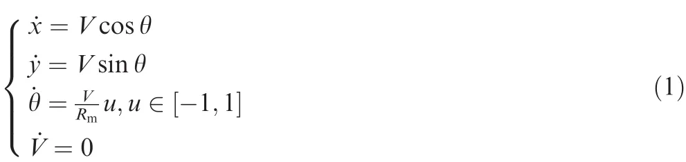
where (x,y)and θ are the planar coordinates and the heading of a missile,respectively,V is the velocity of the missile,Rmis the minimal turning radius,u is the control input,u<0 means turning left with respect to the heading,u>0 means turning right,u=0 means keeping straight flying,and a triplet(x,y,θ)is called a configuration.
The shortest path from one configuration to another must be one of the six Dubins path patterns:RSL,LSR,RSR,LSL,RLR,and LRL,19where L means turning left with the minimal turning radius,R means turning right correspondingly,and S means moving along a straight line.From the conclusions,it can be seen that the shortest Dubins path between two configurations relies on both their positions and headings.
In this research,the heading of a missile at the handover moment is not fixed,so θ in the terminal configuration is unrestricted.It is straightforward to prove that,in the case of terminal heading relaxation,θ in the terminal configuration is unrestricted,and the LS or RS path24is the optimal path when the target is outside of the turning circle of the initial configuration.In battle field situations,the minimal turning radii of missiles are usually hundreds of meters,while the missiletarget ranges in midcourse are at least several times of the minimal turning radii.Hence,the target is certainly outside of the turning circles.The optimal Dubins path pattern of RS/LS will be applied in the path planning calculation.Fig.2 shows the LS and RS Dubins paths,where the initial position of the missile is located at the origin which is denoted by S,and the initial heading of the missile is along the Y-axis.The target is denoted by T′or T,while OLand ORare the centers of left and right turning circles,respectively.The coordinates of OLand ORare(-Rm,0)and (Rm,0),respectively.The coordinates of T′and T are (xT′,yT′)and (xT,yT),respectively.
In the rest of this paper,the RS/LS-type Dubins path with u ∈ [-1,1]is called RS/LS path for short,and the RS/LS path with u=1 or u=-1 is called optimal RS/LS path for short.
3.Cooperative guidance law in the midcourse
As introduced in Section 2.2,the cooperative guidance commands in the midcourse are gained on the basis of the planned paths for the missiles.Firstly,the path patterns of all missiles are settled after the leader is selected and the expected path lengths of followers are known.Then,the parameters in the path pattern of each missile will be calculated according to the expected path lengths.After that,explicit guidance commands can be derived.
3.1.Mid-course cooperative path planning
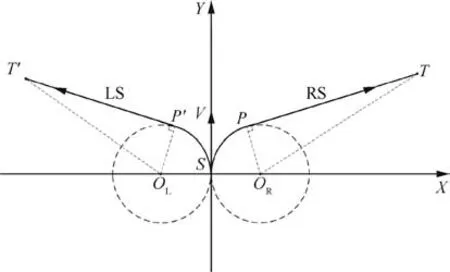
Fig.2 RS/LS Dubins paths with terminal heading relaxation.
In this section,we will show how to calculate the length of the optimal RS/LS path for selecting the leader.Then we propose three path patterns for followers to elongate their paths and introduce applicability conditions.Because the path lengths under the three patterns are monotonous with respect to the respective undetermined parameters,the bisection algorithm is used to calculate the parameters as its effectiveness and convergence rate can be guaranteed.25
3.1.1.Selection of the leader
According to the cooperation strategy,the missile with the longest minimum flight time is selected as the leader,which will follow the optimal RS/LS path for the soonest arrive.To obtain the minimum flight time of each engaged missile and select the leader,the length of the optimal RS/LS path for each missile under the initial conditions is calculated.
Take the optimal RS path in Fig.2 for example.The length is calculated as
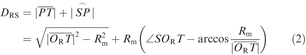
The minimal turning radius Rmand the coordinates of S,OR,and T are known;therefore,and∠SORT can be derived.The shortest flight time of each missile can be obtained as

where Diis the Dubins path length of missile i,and Viis its velocity.
Then,according to the cooperative strategy,the expected flight time^t of all missiles is

The expected path length DEiof each missile is

The missile with ti=^t is selected as the leader to follow its own optimal RS/LS path.The next step is to plan the flight paths for the followers.
3.1.2.Patterns of elongated paths for followers
Because the expected flight times are longer than the calculated minimum flight times of the followers,the main purpose of path planning is to extend the flight times of the followers.However,a missile’s speed should not decelerate with the scruple that improper deceleration for a follower’s flight might cause aerodynamic stall.Therefore,the lengths of the flight paths of the followers will be elongated.Meanwhile,length adjustment and heading alignment should be accomplished at the early stage of the mid-course flight,to achieve a lockon as early as possible.Moreover,the calculation process must be fast and effective since the response time for missiles is limited.In this condition,three patterns of elongated paths for followers are designed.A combination of the applicability conditions for the three patterns can cover the range of all the expected path lengths.For each follower,one of the three patterns will be applied to plan a path with an expected length.The selection of the pattern is determined by both the applicability conditions and the priority order of the path patterns.The priority order from high to low is the circling path,the RS/LS path,and the double-turning path,since small flight coverages and less alternations of the acceleration direction are preferred.
(1)Pattern 1(RS/LS path):Firstly,the most intuitive way to elongate a flight path is magnifying the turning radius in the RS/LS path.However,the extended range of this pattern is relatively narrow because a magnification of the turning radius is subject to the missile-target range and the initial direction of the missile,as shown in Fig.3.The arcis the longest path when magnifying the turning radius in the RS/LS pattern,and the maximum path length in this case is Dmax1=||.The corresponding turning radius is r/(2sinσ)where r is the sight distance and σ is the heading error.In addition,a larger turning radius will result in a larger flight coverage area,which could potentially cause collision or losing communication with the launching platform,especially when the heading error is relatively large.Consequently,the turning radius will be restricted in a certain range.Suppose that Rmaxis the maximum safe turning radius.The maximum path length under the restriction R ≤ Rmaxis Dmax2=DRS(Rmax).Thus,magnifying the turning radius is limited by the two conditions above.Lastly,it will be proven in the appendix(see Theorem 1)that the RS/LS path length DP1monotonically increases with respect to the turning radius R.
Dmax1and Dmax2can be calculated as follows.It is noticeable that the calculation of Dmax2is similar to that of DRSin Eq.(2).

The applicability condition of this path pattern is DE≤ min{Dmax1,Dmax2}.
The length of this path pattern is
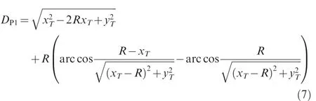

Fig.3 RS/LS optimal Dubins paths with different turning radii.
(2)Pattern 2(circling path):Circling near the start point is a simple solution to cope with the path elongating problem when the expected path length is relatively long.Since circling will be executed at least once,the expected length DEshould be at least 2πRm+DRS.
The applicability condition of this path pattern is

The length of this path pattern is
where the number of circles n and the turning radius R are two unknown variables.Thus,more than one solution may exist for the equation DP2(n,R)=DE.Since a small flight coverage area is preferred,a missile will circle for the maximum n with a small turning radius.Then,the circles number n can be determined in advance for a unique solution as follows:

Because n is determined and the monotonicity of DP1with respect to R is already proven,the monotonicity of DP2with respect to R is obvious.
Therefore,an RS/LS path will be used for a follower if DE< min{Dmax1,Dmax2}.If DE> DRS+2πRm,a circling path will be used.The above two path patterns are enough for the followers to extend their path lengths if min{Dmax1,Dmax2} ≥DRS+2πRm.Otherwise,an eclectic solution is needed if min{Dmax1,Dmax2} < DE< DRS+2πRm.
(3)Pattern 3(double-turning path):An illustration of the double-turning path is shown in Fig.4.The planned path is combined by two circle arcs and a straight line.A flight arc with a certain turning angle δ is executed in advance(see Fig.4).Then,a new optimal Dubins path starting from the new position Srwill be calculated and executed.The minimal turning radius Rmis used in the two circle arcs.The path length is DP3=δRm+DrRS,where DrRSis the path length of the RS/LS path from Srto T.The monotonicity of DP3with respect to δ and the conclusion that DP3covers the range from DRSto DRS+2π ·Rmwill be proven in the appendix(see Theorem 2).The coordinate of T in the XSY coordinate system is(xT,yT).Then,the coordinate of T in the XrSrYrcoordinate system (xTr,yTr)can be calculated as follows:

Fig.4 A double-turning path.

The applicability condition of this path pattern is

The length of this path pattern is

The completeness of the three path patterns:
Based on the above three path patterns,the lengths of elongated paths for the followers range from DRSto+∞,where DRSis the shortest path length to arrive at the target.In this sense,any follower can obtain a desirable planned path from the three path patterns.
As introduced at the outset of Section 3.1.2,one of the three path patterns is selected for each follower.Further,the applicability conditions and the mentioned priority order of the path patterns can uniquely determine the appropriate path pattern for each follower with an expected path length.To intuitively reveal the selections of the path patterns,Table 1 enumerates all the possible cases and the reasons for the selections.
The rationality of the three path patterns is reflected from the following four aspects:
(1)The heading error is eliminated in the soonest way while the path is elongated to the expected length,which will bene fit the locking-on later;
(2)The flight coverage is as small as possible,which reduces the chance that the missile is detected in the early stage of attacking;
(3)There is only one unknown parameter in each path pattern,and the path length of each path pattern is monotonic with regard to each parameter respectively,which facilitates a simple and fast calculation by the bisection algorithm;
(4)The resulting guidance command does not change frequently,as a fickle command may potentially cause instability in the missile’s flight.
3.1.3.Calculation of parameters for follower paths
In order to obtain an elongated path with a selected pattern and an expected length,only one parameter needs to be determined,that is,the turning radius R in Patterns 1 and 2 or δ in Pattern 3.However,the analytical solutions of these parameters are not easy to get since the equations DPi=DEi(i=1,2,3)are transcendental.The bisection algorithm is used in this proposal to solve proper parameters for paths with expected lengths,as long as the path lengths of the three patterns can be calculated with given parameters.Meanwhile,the monotonicity conditions of the path lengths for applying the bisection algorithm are satisfied.25
The pseudo-code of the bisection algorithm is presented in Algorithm 1.

(1)Arguments calculation by the bisection algorithm in the RS/LS path

If the RS/LS path is chosen to obtain the expected path length,the desired turning radius R is calculated by the bisection algorithm with DP1(R)=DE.DE> DP1(Rm)is obvious,and DP1(min{r/(2 ·sinσ),Rmax})-DE≥ 0 is known since the applicability condition for the RS/LS path is satisfied.Therefore,the given bound for R is R ∈ [Rm,min{r/(2sinσ),Rmax}].The output is a proper turning radius R for the followers to apply the RS/LS path.
(2)Arguments calculation by the bisection algorithm in the circling path

If the circling path is chosen to obtain the expected path length,the desired turning radius R is calculated by the bisection algorithm with DP2(R)=DE.DE≥ DP2(Rm)is tenable as the applicability condition for the circling path is satisfied.DP2(2Rm)-DE=DP1(2Rm)+2nπ2Rm-DE> 0, sinceTherefore, the given bound for R is R ∈ [Rm,2Rm].The output is a proper turning radius R for the followers to apply the circling path.

Table 1 Selections of path patterns in all cases.
(3)Arguments calculation by the bisection algorithm in the double-turning path

If the double-turning path is chosen to obtain the expected path length,the desired arc angle δ to satisfy DP3(δ)=DEcan be calculated by the bisection algorithm.DE> DRS=DP3(0)is tenable as the double-turning path is the same as the RS/LS path with a minimal turning radius when δ=0.It can also be proven that DP3(π)> DRS+2πRm> DE(see the appendix for detail).Therefore,the given bound for δ is δ∈ [0,π].The output is a proper arc angle δ for the followers to apply the double-turning path.
3.2.Integrated cooperative guidance command
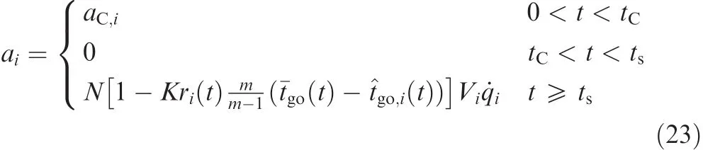
Because the path patterns are simple,it is easy to derive guidance commands corresponding to the three path patterns in Section 3.1.We take the guidance commands α in Fig.5 for example to illustrate the three patterns.tRis the flight time of a missile with a constant normal acceleration in the RS/LS path.tCis the flight time of a missile with a constant normal acceleration in the circling path.tD1and tD2represent a missile’s flight time of the two arcs in sequence in the double-turning path,respectively.
The parameters tR,tC,tD1,and tD2are calculated as follows:

Denote aRand aCthe acceleration values in the RS/LS and circling paths,respectively.Denote aD1and aD2the accelerations corresponding to the two arcs in the double-turning path in sequence.The negative sign in aD1means that the direction deviates from the turning direction in the RS/LS path.
To provide an integrated guidance law,the classic CPN is employed in the terminal course.The simple form of CPN is shown as below.Interested readers may refer to the work of Jeon3for more details.
where N is a constant which is usually set to be around 3,K is the coordination coefficient,riis the sight distance,m is the number of missiles,^tgois the estimate of time-to-go,¯tgois the mean value of all the estimates of time-to-go,and˙q is the rate of LOS.
Each missile will switch into the terminal guidance when the sight distance to the target and the heading error are in a certain range.The switching condition is as follows:

Fig.5 Control commands for generating the planned paths.
where riand ηiare the sight distance and the heading error of the ith missile,respectively.Siand Ciare the maximum sight distance of the seeker and the FOV constraint of the ith missile,respectively.tsstands for the moment when the switching conditions of all engaged missiles are satisfied.
For the ith missile which executes an RS/LS path in the mid-course,the integrated guidance command is

For the ith missile which executes a circling path in the midcourse,the integrated guidance command is
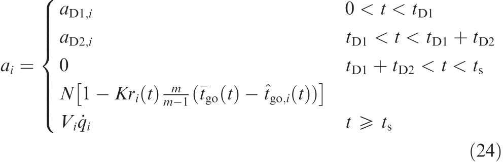
For the ith missile which executes a double-turning path in the mid-course,the integrated guidance command is
Remark 1.The convergence of the cooperative guidance law is guaranteed jointly by the coordinated path planning in the mid-course and the application of CPN in the terminal course.The Dubins paths and the path patterns for elongation are calculated by a geometric method with a fixed initial configuration and terminal position.Therefore,the paths planned in the mid-course will definitely reach the target.Then,the planned paths for the followers are calculated by the bisection algorithm according to the expected flight time.The bisection algorithm is an established method for determining the zero of a monotonic function,and it is considered highly efficient.The path length function of each path pattern has been proven monotonous with regard to the undetermined parameter in the appendix.Therefore,an arrival-time synchronization of the planned paths is guaranteed.In other words,the flight times of the followers converge to the expected flight time which is the same as the minimum flight time of the leader.In this case,the headings and the times-to-go of the missiles at the switching moment satisfy the initial conditions required by CPN for the cooperative terminal guidance.At the terminal guidance phase,CPN is applied,and the convergence of the algorithm has been proven by Jeon3.The impacting error of the missiles and the variance of the arrival time will converge to zero.Therefore,a convergence of the cooperative guidance law is guaranteed.
A smooth switch from the mid-course into the terminal course bene fits the performance of cooperative terminal guidance,and the designed three path patterns have the feature of heading straight toward the target at the transition instant.Then,the accelerations of the missiles at the transition instant tsare zero if the planned paths are traced.However,the configurations of the missiles at the transition instant are crucial to the performance of cooperative terminal guidance.Therefore,we present an analytic method to predict the conditions of the missiles at ts.
To calculate the configurations(positions and headings)of the missiles at the transition instant,we should firstly calculate the headings and the distances of the missiles from the target since the missiles are all heading straight toward the target at that moment.According to the assumption that the missiles switch into the cooperative terminal guidance phase at the moment every missile detects the target,the distance of each missile is calculated as follows:
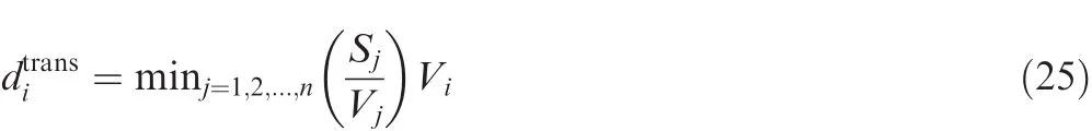
where Sjis the detecting range of each missile.Then we predict the transition instant asIn addition,the heading of every missile at the moment is calculated as follows:
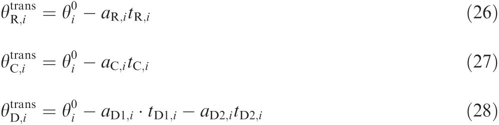
Eqs.(26)–(28)are the calculations corresponding to the RS/LS path pattern,the circling path pattern and the doubleturning path pattern,respectively.is the initial heading of the missile,and the corresponding acceleration is positive if the missile turns right by the command.
Then the position of the missile at the transition instant
wheremeans that the heading is one of,,or.Then the predicted configuration of the ith missile at the transition instant is,,,0)which stands for the position,heading,and acceleration.
4.Simulation and analysis
The simulation consists of three parts so as to demonstrate the necessity of midcourse cooperative guidance and the performance of the proposed coordination methods for multiple missiles,respectively.In each part,three scenarios of simultaneous arrival are performed.The scenarios describe a group of missiles attacking a stationary target with different initial conditions.There are parameters of missiles such as cruising speed,maximum acceleration,and detecting range need to be preset in the simulation.The choices of the parameters in the three parts are made with different special emphasis.
In Section 4.1 the scenarios are designed to clearly represent the three path patterns and illustrate that the proposed guidance method usually has good performance while the comparison method cannot achieve a salvo attack.Therefore,the parameters of missiles are chosen according to the performance indexes of a common cruise missile.The missiles are with cruising speeds around the sonic velocity,the maximum overload is between 6g and 11g,and the detecting range is set to be 8 km.Moreover,the initial headings of missiles are randomly set,while the initial positions are set to generate a result that all three path patterns are applied in each scenario.
In Section 4.2 the scenarios are designed to verify the advantage of the proposed method in the final arrival time of a salvo attack.Therefore,the parameters of missiles are similar to those in Section 4.1.Moreover,the initial headings are also randomly set,but the initial positions are set to ensure that the comparison method can also achieve a salvo attack.
In Section 4.3 the scenarios are designed to illustrate the robustness of the proposed method.Therefore,the missiles are assumed to be various.The missile speeds vary from Mach 0.82–1.62,the maximum overload is between 9g and 22g,and the detection range could be 8 km,9 km,or 10 km.The initial positions and headings are all randomly generated.
Lastly,the maximum turning radius Rmaxis set to be 2Rmfor all the missiles when calculating the applicability condition of the path patterns.
4.1.Verifying necessity of midcourse cooperative guidance
In this part,the midcourse guidance law with a terminal handover constraint recently proposed by Morgan15is combined with CPN in the terminal course to perform cooperative guidance.This composite method is named Morgan&CPN here and used for comparison.The two constraints described in Section 1 are taken into consideration.Hence,we assume that the missiles will not join the terminal cooperative guidance if they have not yet locked on the target at that moment,and the first several missiles that have locked on the target activate the cooperative terminal guidance.Then,missiles that lock on the target afterward can join the cooperation and play an equal role only if the previous ones are not about to reach the target.In the terminal course,we consider the missiles as losing the track of the target and seceding from the terminal guidance if they generate heading errors that are larger than the FOV constraint on account of detouring.The FOV constraint is that the heading error is between ±75°.The initial conditions of engaged missiles are listed in Table 2,Fig.6 shows the simulation results of the three scenarios when applying the above mentioned guidance scheme.In Fig.6,the dashed lines depict the flight paths of four engaged missiles.The marks of a small circle stand for the handover points that the missiles have locked on the target.The marks of a diamond stand for the moment that missiles join the cooperative terminal guidance.
The flight times of those missiles hitting the target are presented in Table 3.
The results shown in Fig.6 and Table 3 are further expatiated to make the scene clear.In Scenario A1,Missile 4 and Missile 2 successively acquire the target at 47.80 s and 56.41 s,and CPN takes over the terminal guidance of both missiles at the moment when Missile 2 locks on.Missile 3 joins the cooperative terminal guidance later at 56.48 s when it acquires the target.However,Missile 4 loses the target at 60.79 s due to the violation of the FOV constraint when detouring,though CPN rapidly impels Missile 3 to head straight to the target to shorten the flight time.After that,Missile 2 and Missile 3 hit the target at 81.40 s and 81.52 s,respectively.Missile 1 has not acquired the target yet when Missile 2 and Missile 3 hit the target.
In Scenario A2,Missile 3 hit the target alone at a much earlier time that is 51.09 s.Missile 1 and Missile 2 successively acquire the target and successfully hit the target simultaneously at 73.10 s.Missile 4 acquires the target too late at 63.57 s when Missile 1 and Missile 2 are already very close to the target,so it cannot join the terminal cooperation.
In Scenario A3,Missile 4 and Missile 2 successively acquire the target at 41.70 s and 55.52 s.Then the terminal cooperation starts at 55.52 s.Missile 4 loses the target in the cooperative guidance with Missile 2 at 60.12 s.At last,Missile 2 hit the target alone at 77.74 s.Missile 1 and Missile 3 have not acquired the target until the cooperative guidance ends in failure.
The results shown in these simulations illustrate the necessity of the mid-course cooperative guidance when missiles perform a simultaneous attack.If we postpone the launching times of the missiles that have a shorter flight time or alter the launching angles in order to ameliorate the initial condition for the terminal cooperation,it will excessively increase the period of occupation of the engaged platform since the initial launching conditions are rigorous.In this proposal,the launching platform is able to launch a missile right away and forget.The platform is out of occupation and ready for other subsequent tasks right after launching.
As comparison,simulations with the proposed cooperative guidance law applied in the same scenarios are shown.First of all,the optimal RS/LS flight paths for all missiles will be calculated at the start moment of the cooperative attack assignment.The minimum flight times of the four missiles in the three scenarios can be obtained,which are shown in Table 4.Then,the missile with the longest minimum flight time,that is Missile 1 in Scenario A1,Missile 4 in Scenario A2,or Missile 1 in Scenario A3,will be selected as the leader and follow the optimal RS/LS path.The flight time of the leader will be applied as the flight time constraint in path planning of the other missiles.The expected path length of each follower can be calculated according to the expected flight time and its own speed.
In the coordinated path planning process,the path pattern for each missile will be chosen according to Table 1.After the path patterns are confirmed,the bisection algorithm is used in this proposal to find the proper parameters for the paths with expected lengths.Fig.7 depicts the planned flight paths of the four engaged missiles to attack the target simultaneously.Control commands for these planned paths are shown in Fig.8.
The control commands shown in Fig.8 will be used as the guidance law in the midcourse of missile flights,and then all the engaged missiles will approach the target and generate paths that are similar in path length.When all the missiletarget distances and missile heading errors satisfy the lock-on condition,the missiles start the cooperative terminal guidance.The lock-on condition in this simulation is that the sight distance is less than the detection range and the heading error is less than 30°.Moreover,according to the calculations in Section 3.2,the predicted configurations of the missiles at the switching instant are:(5114,6126,-129.9°,0),(-6440,4563,-35.3,0),(4169,-6819,129.7°,0),(-6156,-5109,39.7°,0)in Scenario A1,(-4047,5706,-54.7°,0),(6749,4295,-147.5°,0),(5819,-5182,138.3°,0),(-4194,-5733,53.8°,0)in Scenario A2,and(-4434,5328,-50.2°,0),(6011,5278,-138.7°,0),(6122,-4048,146.5°,0),(-5772,-4013,-145.2°,0)in Scenario A3.
Table 2 Initial conditions of engaged missiles.

Fig.6 Flight paths without midcourse cooperative guidance.
Table 3 Simulation record of missiles without midcourse cooperative guidance.
Fig.9 depicts the paths generated by the joint cooperative guidance in the midcourse and the terminal course.The flight paths in the midcourse are indicated by solid lines,and the terminal course paths by the terminal guidance law are indicated by dashed lines.The four rhombuses denote the points that missiles switch into cooperative terminal guidance at the same time.It is obvious that the ZEM at the handover points of all missiles is sufficiently small,which is preferred for acquiring the target.As compared with Fig.6,Fig.9 demonstrates that the proposed cooperative midcourse guidance ensures a successful simultaneous attack,and the initial launching condition is relaxed.
In Scenario A1,Missile 1 with the longest minimum flight time of 86.88 s is selected as the leader.At 62.14 s,all missiles have locked on the target and switch into the cooperativeterminal course.The heading errors of all missiles and the variance of time-to-go at the hand-off moment are sufficiently small.Then,cooperative terminal guidance is carried out successfully.In Scenario A2,Missile 4 is selected as the leader.At 44.33 s,all missiles switch into the cooperative terminal course.Cooperative terminal guidance is also carried out successfully.In Scenario A3,Missile 1 is selected as the leader.All missiles switch into the cooperative terminal course at 62.50 s.
Table 4 Simulation record of the engaged missiles.

Fig.7 Planned flight paths of four engaged missiles.

Fig.8 Mid-course guidance commands.
Fig.9 Flight paths by proposed method(Scenario A1–A3).
Table 5 Parameters of scenarios for attack time comparison.
Table 6 Final attack time obtained by two methods.
At the hand-off moments,all the missiles have locked on the target,and the time-to-go is estimated if traditional PNG is carried out in the terminal course as shown in Table 4.The final arrival time of the engaged missiles is also shown.It is obvious that due to the cooperative mid-course guidance,the variance of the time-to-go at the hand-off moment is much less than the variance of the RS/LS path flight time at the initial moment.Moreover,the variance of the final arrival time almost decreases to zero when the cooperative terminal guidance course is over.The maximum difference among the impact times of engaged missiles is 0.32 s in Scenario A1,0.27 s in scenario A2,and 0.37 s in Scenario A3.It is rational to indicate that the four missiles impact on the target almost at the same time by applying the proposed guidance law in each scenario.
4.2.Simulations to illustrate advantage of a quick salvo attack
The applicable scenarios for Morgan&CPN are much fewer than those for the proposed method.The scenarios for comparison are those in which a salvo attack can be realized by both methods.The parameters are listed in Table 5.The results of the two methods are presented in Table 6 and Fig.10.
As shown in Table 6,the final attack times of the missiles obtained by applying the proposed method are surely much earlier than the counterpart by Morgan&CPN.Therefore,the proposed cooperative strategy is advantageous in the final arrival time of a salvo attack.Moreover,elongations of path lengths are accomplished at the early stage of the mid-course flights.As a result,the flight paths in the terminal course are smooth and short,which is also advantageous in a battle field.
4.3.Simulations to illustrate robustness of proposed method
In this part,the performance of the proposed method is further validated by various scenarios.Parameters such as the number of engaged missiles,the locations of the missiles,and the capabilities of the missiles are different in the scenarios.The final arrival times of the missiles,the variance of final arrival times,and the variance of times-to-go by PNG at the hand-off moment indicate the cooperative guidance performance.
Three different scenarios are presented here.The considered performance indexes of missiles are the missile speed,the maximum acceleration,and the detection range of the seeker.The parameters of missiles in every scenario are shown in Table 7.The flight paths are shown in Fig.11.The records of simulations are presented in Table 8.In Scenario C1,Missiles 1 and 2 are from one field and have better performances than those of Missiles 3 and 4 from another field.In Scenario C2,five missiles are engaged,in which Missiles 1 and 2 are from one field,and Missiles 3,4,and 5 from another field with much longer distances to the target.In Scenario C3,Missile 5 alone is from one field which is much closer to the target in contrast with the other field,in which the rest four missiles have much better performances.
Fig.10 Comparison between Morgan&CPN and the proposed method.
Table 7 Parameters of simulation scenarios.

Fig.11 Flight paths by proposed method(Scenario C1-C3).
Table 8 Simulation records of the scenarios.
The simulation results are quite satisfying in different scenarios with various parameters and tactical characteristics. As illustrated by Table 8 and Fig.11,the engaged missiles in each scenario have accomplished a salvo attack.The variances of the final arrival times are small enough,and the adjustment of flight path lengths is achieved at the early stage of the midcourse flight owing to the effective path patterns for elongation.At the cooperative terminal guidance switching point indicated by the rhombuses,all the missiles have acquired the target and switched into cooperative terminal guidance successfully.In Scenario C1,the speed of Missile 2 is nearly twice of Missile 3.In Scenario C2,the minimum flight time of Missile 4 is more than twice of Missile 1 or 2.Even with such speed differences,the proposed method still achieves salvo attack efficiently.Moreover,it is noticeable that the final arrival times of engaged missiles in every scenario are very close to the longest one among the minimum flight times of all the missiles which is theoretically the earliest completion time of a salvo attack. In this sense, the proposed method also achieves a soonest salve attack.
5.Conclusions
This paper proposes a joint mid-course and terminal course cooperative guidance law for supporting a salvo attack of multiple missiles with different initial conditions.The mid-course cooperative guidance law is derived from path planning for all missiles under a distinct leader-follower framework.Dubins paths with terminal heading relaxation and three path patterns for followers ensure a soonest salvo attack.When all missiles lock on a target,cooperative guidance will switch from the mid-course to the terminal course.Cooperative proportional navigation is employed as the terminal cooperative guidance law in order to lead the missiles to impact on the target simultaneously.The synergy of these two courses provides an effective solution for multiple missiles to salvo attack a surface target,especially for long-and medium-range missiles or stand-off attacking.As for the mid-course guidance,the proposed three path patterns for followers and the corresponding path calculation method based on the bisection algorithm are very simple to implement.Simulations validate the effectiveness of the joint cooperative guidance law.
Acknowledgements
The leader-follower framework for joint mid-course and terminal course cooperative guidance of multiple missiles in a salvo attack is proposed by Bin Xin.Bisection algorithms for different path patterns are built and implemented by Jie Zeng under the guidance of Bin Xin and Lihua Dou.The work of Bin Xin is supported by the National Natural Science Foundation of China(No.61304215).The work of Lihua Dou is supported by the Beijing Education Committee Cooperation Building Foundation Project(CSYS100070417).
Appendix A
Theorem 1.In the RS/LS pattern of an optimal Dubins path,the path length will monotonically increase if the turning radius is magnified.
Proof.Due to the symmetry,the RS path will be illustrated in the proof,and the same approach can be applied for the LS path.As shown in Fig.A1,the missile path starts from point S,the target is located at T,the LOS distance between S and T is r,the initial heading is represented by V,σ is the initial heading error,and the turning radii for two RS paths are R and R+Δ,respectively.The Path RS1with R as the turning radius is composed ofand,and α is the angle ofwhile OR1is the center.The Path RS2with R+Δ(Δ>0)as the turning radius is composed ofandand β is the angle ofwhile OR2is the center.Line OR1P1intersects withat A,and the angle of ∠OR1AOR2is θ.
Firstly,
where

If||≥||,the conclusion can be proven then.
Fig.A1 Two RS paths with different turning radii.
Obviously,

When α ≥ π,α= β- θ so that||≥||,and then the conclusion is proven.
When α < π,α = β +θ,and

then

De fine

Set λ=and 0< λ < 1,and then 0< λ ·α < π.If λα >then F(α)> 0,and the conclusion is proven.When 0≤ λα ≤we can get λα > sin-1(λsinα)if sinsinα because of the monotonicity of the sine function in.De fine

Obviously,G(0)=0 and˙G(α)=cos(λα)-cosα>0,which leads to

Therefore,F(α)≥ 0 when 0≤ λ·α≤
Therefore,the path length will monotonically increase with respect to the turning radius in the RS/LS pattern. □
Theorem 2.In a double-turning path,the path length will monotonically increase with respect to the angle δ.
Proof.The recursive method is used in this proof.

Fig.A2 Double-turning paths with the first arc angles being δ and δ + τ.
As shown in Fig.A2, flight Path 1 is an RS pattern path when δ=0,while Path 2 is a double-turning path.Both of them start from S,and end at T.The turning radii in the two paths are the same,so that Path 2 is longer than Path 1 because the RS pattern path is the shortest path when the initial position and direction,the final position,and the turning radius are fixed.20
Consider Path 3 which is a double-turning path with the first arc angle being δ + τ (τ> 0).If ignoring the flight arc angle δ,the rest of path 2 is an RS pattern path starting from Sr,and the rest of path 3 is a double-turning path starting from Sr.
Therefore,it is obvious that Path 3 is longer than Path 2,and Path 2 is longer than Path 1,as long as δ > 0,τ> 0.In other words,the length of the double-turning path will monotonically increase with respect to the angle δ.
Besides,it is also obvious that the length of the doubleturning path is longer than D(RS)+2πRmif δ > π.Then the path length in this pattern can range from D(RS)to D(RS)+2πRm,and the double-turning path is a logical choice when the expected path length is between min{Dmax1,Dmax2} and D(RS)+2πRm. □
1.Jeon IS,Lee JI,Tahk MJ.Impact-time-control guidance law for anti-ship missiles.IEEE Trans Control Syst Technol 2006;14(2):260–6.
2.Lee JI,Jeon IS,Tahk MJ.Guidance law to control impact time and angle.IEEE Trans Aerosp Electron Syst 2007;43(1):301–10.
3.Jeon IS,Lee JI.Homing guidance law for cooperative attack of multiple missiles.J Guid Control Dyn 2010;33(1):275–80.
4.Zhao SY,Zhou R.Cooperative guidance for multi-missile salvo attack.Chin J Aeronaut 2008;21(6):533–9.
5.Zou L,Kong FE,Zhou R,Wu J.Distributed adaptive cooperative guidance for multi-missile salvo attack.J Beijing Univ Aeronaut Astronaut 2012;38(1):128–32[Chinese].
6.Zhao SY,Zhou R,Chen W.Design of time-constrained guidance laws via virtual leader approach.Chin J Aeronaut 2010;23(1):103–8.
7.Zhang YG,Zhang YA.Three-dimensional guidance law to control impact time and impact angle:A two-stage control approach.Control Theory Appl 2010;27(10):1429–34.
8.Zhang YA,Ma GX,Liu AL.Guidance law with impact time and impact angle constraints.Chin J Aeronaut 2013;26(4):960–6.
9.Zhang YA,Wang XL,Wu HL.Impact time control guidance law with field of view constraint.Aerosp Sci Technol 2014;39:361–9.
10.Zhang YA,Wang XL,Wu HL.A distributed cooperative guidance law for salvo attack of multiple anti-ship missiles.Chin J Aeronaut 2015;28(5):1438–50.
11.Zhao J,Zhou R.Unified approach to cooperative guidance laws against stationary and maneuvering targets.Nonlinear Dyn 2015;81(4):1635–47.
12.Zhao J,Zhou R,Dong Z.Three-dimensional cooperative guidance laws against stationary and maneuvering targets.Chin J Aeronaut 2015;28(4):1104–20.
13.Zeng J,Dou LH,Xin B.Cooperative salvo attack using guidance law of multiple missiles.J Adv Comput Intelligence Intelligent Inf 2015;19:301–6.
14.Zhou J,Yang J,Li Z.Simultaneous attack of a stationary target using multiple missiles:a consensus-based approach.Sci China Inform Sci 2017;60(7):1–14.
15.Morgan RW. Midcourse guidance with terminal handover constraint. Proceedings of the American control conference; 2016 July 6–8; Boston, MA. Piscataway: IEEE Press; 2016. p. 6006–11.
16.Guelman M.A qualitative study of proportional navigation.IEEE Trans Aerosp Electron Syst 1971;7(4):637–43.
17.Ho YC,Bryson Jr AE,Baron S.Differential games and optimal pursuit-evasion strategies.IEEE Trans Autom Control 1965;10(4):385–9.
18.Indig N,Benasher JZ,Sigal E.Near-optimal minimum-time guidance under spatial angular constraint in atmospheric flight.J Guid Control Dyn 2016;39(7):1–15.
19.Dubins LE.On curves of minimal length with a constraint on average curvature and with prescribed initial and terminal positions and tangents.Am J Math 1957;79(3):497–516.
20.Tanil C.Cooperative path planning for multiple missiles-An evolutionary speciation approach.AIAA guidance,navigation,and control conference;2012 Aug 13–16;Minneapolis,MN.Reston:AIAA 2012.p.1–13.
21.Meyer Y,Isaiah P,Shima T.On Dubins paths to intercept a moving target.Automatica 2015;53:256–63.
22.Wang L,Yao Y,He FH,Liu K.A novel cooperative mid-course guidance scheme for multiple intercepting missiles.Chin J Aeronaut 2017;30(3):1140–53.
23.Yao W,Qi N,Zhao J,Neng W.Bounded curvature path planning with expected length for Dubins vehicle entering target manifold.Robot Auton Syst 2017;97:217–29.
24.Xin B,Chen J,Xu DL,Chen YW.Hybrid encoding based differential evolution algorithms for Dubins traveling salesman problem with neighborhood.Control Theory Appl2014;31(7):941–54.
25.Parida PK,Gupta DK.A cubic convergent iterative method for enclosing simple roots of nonlinear equations.Appl Math Comput 2007;187(2):1544–51.
 CHINESE JOURNAL OF AERONAUTICS2018年6期
- CHINESE JOURNAL OF AERONAUTICS的其它文章
- An efficient aerodynamic shape optimization of blended wing body UAV using multi- fidelity models
- Effect of multiple rings on side force over an ogive-cylinder body at subsonic speed
- Dynamic temperature prediction of electronic equipment under high altitude long endurance conditions
- Experimental investigation on static/dynamic characteristics of a fast-response pressure sensitive paint
- Takagi-Sugeno fuzzy model identification for turbofan aero-engines with guaranteed stability
- Experimental study on film cooling performance of imperfect holes