
Cathode erosion site distributions in an applied-field magnetoplasmadynamic thruster
2020-09-14 01:13PengWU吴鹏YibaiWANG王一白YongLI李永BaojunWANG王宝军KaiyuZHANG张凯宇HaibinTANG汤海滨andJinbinCAO曹晋滨
Plasma Science and Technology 2020年9期
关键词:海滨
Peng WU (吴鹏),Yibai WANG (王一白),Yong LI (李永),Baojun WANG (王宝军),Kaiyu ZHANG (张凯宇),Haibin TANG(汤海滨) and Jinbin CAO (曹晋滨)
1 School of Astronautics,Beihang University,Beijing 100191,People’s Republic of China
2 Beijng Institute of Control Engineering,Beijing 100190,People’s Republic of China
3 School of Space and Environment,Beihang University,Beijing 100191,People’s Republic of China
4 Key Laboratory of Spacecraft Design Optimization &Dynamic Simulation Technologies,Ministry of Education,Beijing 100083,People’s Republic of China
5 Laboratory of Space Environment Monitoring and Information Processing,Ministry of Industry and Information Technology,Beijing 100083,People’s Republic of China
Abstract
Keywords:electric propulsion,applied-field magnetoplasmadynamic thruster,cathode erosion,magnetic field,propellant mass flow rate
1.Introduction
The magnetic field which is perpendicular to arc column plays an important role in vacuum arc facility [1],the magnetoplasmadynamic thruster (MPDT) is not an exception.MPDT utilizes the Lorenz force to convert electrical energy into propellant axial kinetic energy.The increasing number of satellites has resulted in greater consideration of electric propulsion as potential thruster systems[2,3].MPDT are one of the primary candidates for high energy space exploration missions due to their high specific impulse and thrust density[4-7].However,the operational lifetime of typical MPD thrusters is insufficient for such space missions and is one of the main limitations to the application of MPD thrusters [8].The life of an MPD thruster is mainly dictated by the life of the cathode [9].The cathode erosion mechanism varies with different devices and also with different stages in the operation of a given device:these can be divided into a start-up stage and a steady-state stage [10].During the start-up stage,there are quantities of tiny spots on the cathode surface,the current density of which can reach 1012A m−2[11].Due to this high current density,local corrosion and sputtering are the main cause of the erosion.When thrusters reach a stable operation stage,the cathodes work in a diffuse mode [12].Those current densities are much lower than the start-up stage,while the overall cathode temperature will be much higher,even close to the melting point [13,14].Thus,evaporation is dominant in the steady-state stage [14].Research has shown that cathode erosion occurs mainly during the start-up stage,and the erosion rates of the two stages differ by three to four orders of magnitude [15,16].
Research on cathode erosion has focused on microcosmic erosion mechanisms [17-20].The formation and development of cathode spot in vacuum arc were well described in recent years [21,22].However,the distributions of the cathode spot on the cathode surface were not investigated.In fact,the erosion location can also significantly affect the cathode life.Cathode erosion usually concentrates in the middle of cathodes [16,23,24],with adverse effect.If the cathodes can be consumed from the top or eroded uniformly on the outer cylindrical surface,the cathode life can be greatly extended.This research is directed to understanding erosion sites for the purpose of extending cathode lifetime of MPD thrusters.
To identify effects of erosion due to spot location,Kimura [25-27]divided a hollow cathode into two parts and measured the current flowing through the segments.By combination of six groups of divided cathodes,Kimura mapped current densities on cathode surfaces.However,artificially separating the cathode may have influenced the original current distribution,and the results are anecdotal.
Schrade [11]investigated erosion using the procedure of significant repetition of an operating condition to make the mass loss of the cathode more significant.He repeated ignition experiments 30-50 times to measure the erosion rate during the starting phase;he operated the thruster for 60-240 min to measure the erosion rate of steady state.These experiments were extremely time-consuming,and effects of only a few working parameters were evaluated.The research provided information on erosion rates,but there was no discussion about the erosion sites.
To measure the erosion rate at selected points,Polk[28,29]used a Surface Layer Activation technique.The method not only provided submicron level accuracy,but also can be employed to measure the erosion rates of anode,cathode and insulator.Nevertheless,the method can only measure the erosion rate at several selected areas,not the whole cathode surface.
In this paper,graphite was used as the cathode material to more clearly identify the effects of the cathode erosion.Compared to traditional cathode material such as tungsten or thoriated tungsten,the erosion rate of graphite is much higher.As a result,only 20 s was needed to obtain significant erosion grooves on a new cathode for one operation condition.Ten cathodes were employed in the experiments,corresponding to ten different operation conditions;these include different applied magnetic field strengths,applied magnetic field positions,anode propellant mass flow rates and cathode propellant mass flow rates.With these results,the influence of these working parameters on cathodic erosion position was analyzed,and the data were used to construct a theoretical location model.
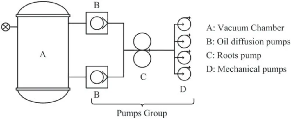
Figure 1.Schematic diagram of vacuum system.

Figure 2.Schematic diagram of AF-MPDT structure.
2.Experiment
2.1.Vacuum facility
A controlled vacuum environment is necessary to conduct experiments on MPD thruster operation.A schematic of the vacuum system used in the experiments is shown in figure 1:the main components are the vacuum chamber,a triple-stage pump group and controllers.The vacuum tank was 3 m(diameter)×5 m (height) and was made of 304 stainless steel.The group of pumps was comprised of four mechanical vacuum pumps,one Roots pump and two oil diffusion pumps.The ultimate vacuum of the system was 5×10⁻⁴Pa;the working pressure was 5×10⁻²Pa when the mass flow rate of propellant was no more than 21 mg s−1with argon propellant.
2.2.AF-MPD thruster
The thruster used in the experiment was a 10 kW class AFMPDT[30,31],and its structural schematic diagram is shown in figure 2.The main thruster components are cathode,anode and insulator.There is a ring clearance between the anode and insulator,propellant can flow into the discharge chamber through the clearance,and this is called anode propellant.Propellant can also be supplied through a channel inside the hollow cathode,and this is called cathode propellant.
The anode length and inner diameter are 30 mm.The cathode itself was made of graphite,this was chosen because its erosion rate is relatively high compared to standard MPD thruster models [32].The cathode is 13 mm long,6 mm in outer diameter and 3 mm in inner diameter.As significant erosion can be obtained after thruster operation for a short time,every graphite cathode was used only once in one experiment to ensure that the erosion trace is formatted under only one operating condition.
A solenoid coil was placed coaxially to the thruster axis to generate a convergent-divergent magnetic field geometry.The relative axial position between the coil and the thruster body could be adjusted to allow evaluation of its effect on erosion sites.The distance between the center of the coil and the end of the cathode is SM-C.As shown in figure 3,the magnetic coil was formed by 240 turns of hollow wire,which acted as the passage for both electric current and coolingwater.We will take the magnetic field strength at the center of the coil as a representative descriptor of the whole magnetic field.

Figure 3.Schematic diagram of magnetic coil.
2.3.Experiment procedure
Four operation parameters were examined to determine their influence on cathode erosion:the relative axial position of the magnetic coil(SM-C);the applied magnetic field strength(Ba);anode propellant mass flow rate(a);cathode propellant mass flow rate (c);discharge voltage (Vd) and discharge current(Id).Data were recorded for ten different thruster operation configurations in order to determine the effects of these four parameters;the operations map is shown in table 1.The detail operation processes of the ignition can be found in [33].
The amplitude of the discharge current has influence on the formation of the cathode crater.However,the discharge current lacks the impact on the erosion sites,according to the equation(13).The discharge current is fixed on 150 A in this paper.Some description of the mapping is as follows.Three different orientations of thruster and applied field are:SM-C,0 mm (No.2 in table 1),6.1 mm (No.1 in table 1) and 12.3 mm(No.4 in table 1),according to the length of the cathode,extending out of the insulator,which is 12.3 mm.Three different applied field strengths were employed:Ba=0 mT(No.6 in table 1),Ba=68 mT (No.1 in table 1) and Ba=102 mT (No.7 in table 1).To evaluate the effect of anode/cathode mass flow rate feed,propellant mass flow rates ofa=16.8 mg s−1,c=4.2 mg s−1were chosen as a basic condition(No.1 in table 1),where the ratio ofatocis 4:1 and the total mass flow rate is 21 mg s−1.A second propellant feed configuration enlarged the total mass flow rate to 1.5 times basic condition,while keeping the ratio constant(No.8 in table 1).Third,the ratio was changed to 1:4,while the total mass flow rate was kept constant (No.9 in table 1).
The configuration for No.10 in table 1 is a limiting condition of no propellant feed except through the cathode,and it was expected to exaggerate the erosion effects.In order to verify repeatability,in the 1-10 sequence of the experiments,No.3 and No.5 operation conditions were the same as No.2 and No.4.Each experiment was conducted with a new cathode,which was operated for 20 s.Further details of experiment operations can be found in [25].
2.4.Experiment results
As shown in figure 4,there are two different operating modes of cathode:starting with a cold cathode (starting phase) and steady-state operation.The duration of starting phase is 5 s approximately.The voltage oscillates seriously in this operating mode,which means severe ion sputtering.When the cathode is hot enough,the discharge becomes stable and quiet.The cathode erosion in starting phase is much more serious than that in steady-state operation [11].
The visual appearance of cathode erosion was photographed and is shown in figure 5.Data conditions correspond to thruster operation parameters identified in table 1.The green dashed line in the figures represents the location of the center of the magnetic coil.Figure 5 presents images of the locations of cathode erosion for different magnetic field conditions.Figure 5(a) provides evidence of data variability for different magnetic geometry axial positions.Figure 5(b)shows the erosion patterns for different magnetic field strengths.Figure 6(a) shows cathode erosion for different propellant mass flow rates.Figure 6(b)shows cathode erosion for different anode propellant mass flow rates.
According to these erosion images,it can be found that the erosion always distributes around cathode tips.Here we define SE-Cas the width of erosion range,and the varying of SE-Cwith axial magnetic field positions and applied field strengths is shown in figures 7 and 8.According to figure 7,SE-Cincreases with SM-C.In combination with figure 5(a),the cathode erosion degree did not be worse,despite that erosion range on the out surface becomes narrower.Considering that the total discharge current keeps constant in the experiments,thus the conclusion can be drawn that moving the magnetic coil to downstream can push the arc attachment points to the inner surface of hollow cathode.
According to figure 8,SE-Cdecreases linearly with applied field strengths.The experimental results are coincide with the conclusion of [25],according to which,with the increase of magnetic field strengths,the current density around the cathode base decreases,while the density in the downstream of cathode increases.
Examination of the data regarding location of cathode erosion sites allows the following conclusions to be drawn from the experimental results:
(1) When the applied magnetic field was zero,the cathode erosion was concentrated at one point,and the erosion was most serious.
(2) In the presence of an applied magnetic field,the erosion sites on the cathode surface were distributed around the circumferential direction of the external surface and appeared to be less serious than that without a magnetic field.
(3) When the magnetic field was strengthened,the erosion range was reduced in size and moved slightly downstream of the magnetic field center.
(4) When the cathode and anode mass flow rate was increased,the erosion range was reduced in size and was slightly downstream.
(5) When the anode mass flow rate was reduced,the erosion range of the cathode surface was more diffuse and upstream;the range of the diffuse cathode discharge became larger with lower anode mass flow rate.

Table 1.Thruster operation conditions for the evaluation of cathode erosion spot location.
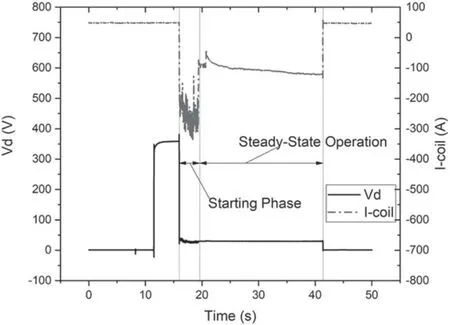
Figure 4.The variation of discharge voltage and coil current in condition 1.
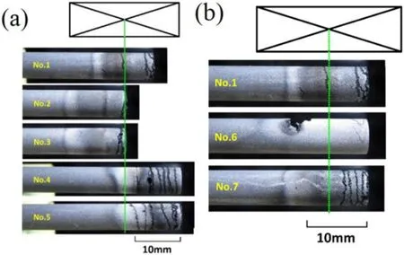
Figure 5.Cathode erosion data variability under different magnetic field positions (a) and magnetic field strengths (b).
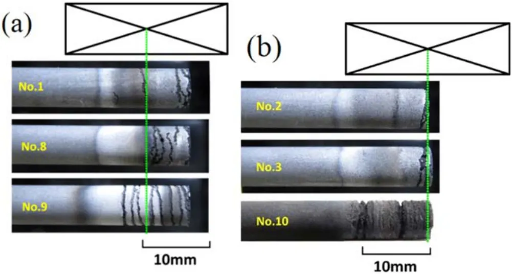
Figure 6.Variable mass flow with the center of coil placed in the middle of cathode (a) and the top of cathode (b).
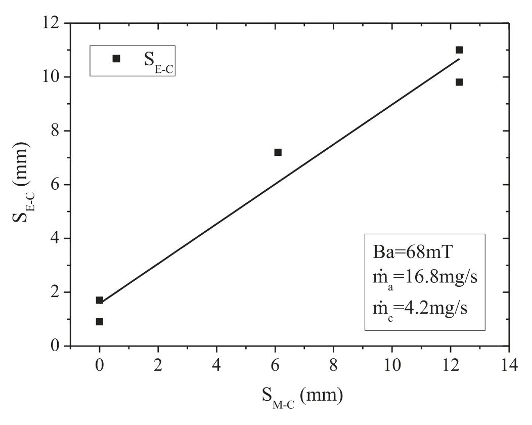
Figure 7.The influence of magnetic field positions on the cathode erosion sites.
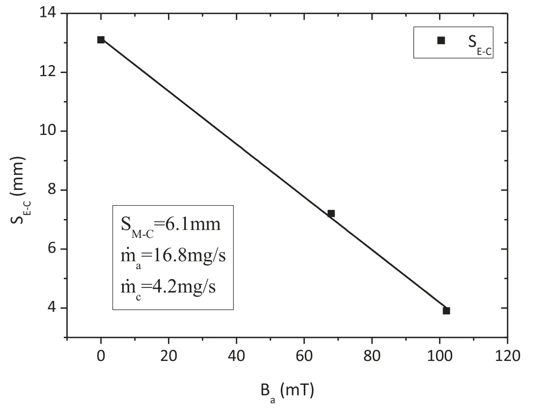
Figure 8.The influence of magnetic field strength on the cathode erosion sites.
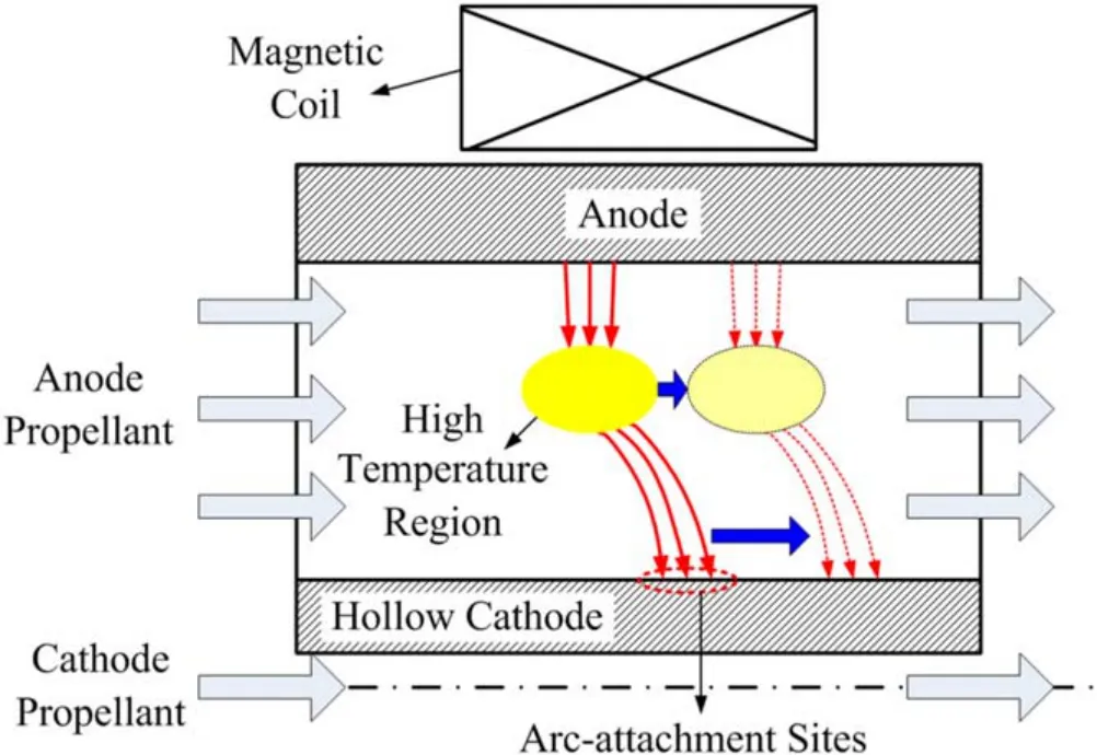
Figure 9.Movement of arc attachment sites with high temperature region.
3.Analysis and discussion
As shown in figure 9,the distributions of erosion grooves on the surface of cathodes are annular,which relates to the similar patterns of the moving modes of the discharge arc under an applied magnetic field [34,35].Thus,the erosion grooves apparently are traces of arc attachment points;their behavior pattern can be incorporated into an analysis to attempt to identify controlling variables in cathode erosion spot location.The anode will play an active role by emitting vapor into the plasma column when the current density is very high [36].Considering the discharge current in this thruster(150 A) is much lower than that in [36](in the order of 1000 A),the influence of the anode is neglected in this paper.
The discharge current was constant in all experiments.The erosion sites on the cathode are the positions where the discharge arcs were attached.High discharge currents will be related to high plasma conductivity,and according to the Saha ionization equation [37],this will be related to an increase of temperature,and so the concentrated discharge current causes significant erosion and significant local plasma heating.
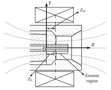
Figure 10.Geometry and coordinates used for analysis of cathodes erosion sites.
The local current flow can be described by appealing to the generalized Ohm’s law,and a simplified version equation (1) can be obtained by ignoring the small axial and azimuthal component of electric field and radial component of field.According to the infinite straight wire model,the induced magnetic field from 1 mm on the cathode surface is 0.001 T which is much smaller than that generated by coil(0.068 T).The influence caused by induced magnetic field can be neglected,we then get equation (2)

The coordinate system is shown in figure 10.In addition,zMis defined as the axial position of coil center and zEis defined as the location of upstream-boundary of the erosion region.
The components of J can be expressed as:
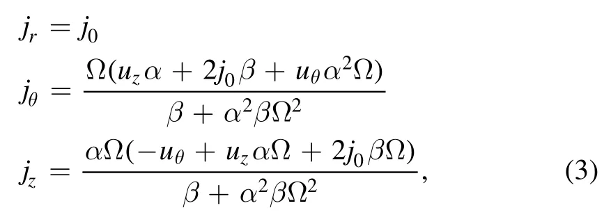
where

The Joule heat Q caused by discharge current can be expressed as equation(5),with subsequent evaluations where it is assumed that uzlinearly increases with z,as:
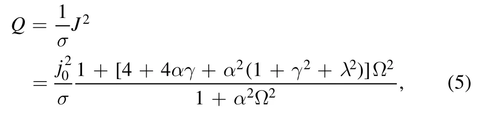
where
For a small α,the higher-order terms can be ignored.Then the Joule heat Q can be simplified into:
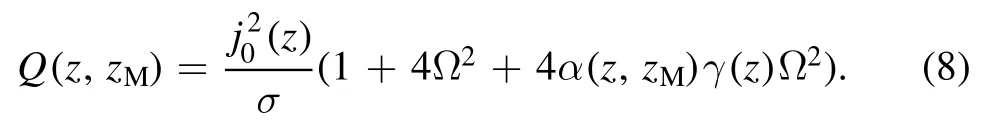
If it is assumed that Joule heating is the same over all operation conditions,get:

with the erosion point at zE0,when zM=0,from which the following can be derived
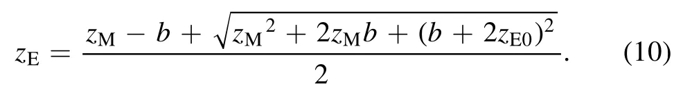
The variation (partial derivative) of zE,with respect to zM,is expressed in equation (11).The value ofis always larger than zero,which means the erosion point will move towards the downstream with increasing zM.
The(variation)partial derivative of zE,with respect to b,is expressed in equation (12),the value of which is also always larger than zero.According to equation (6),the value of b is linear with uz,which is linear with mass flow rate.Thus,this is an analytic relationship that decreasing anode mass flow rate can cause

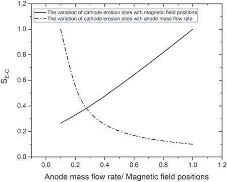
Figure 11.The variation of erosion sites with anode mass flow rate and magnetic field strength.
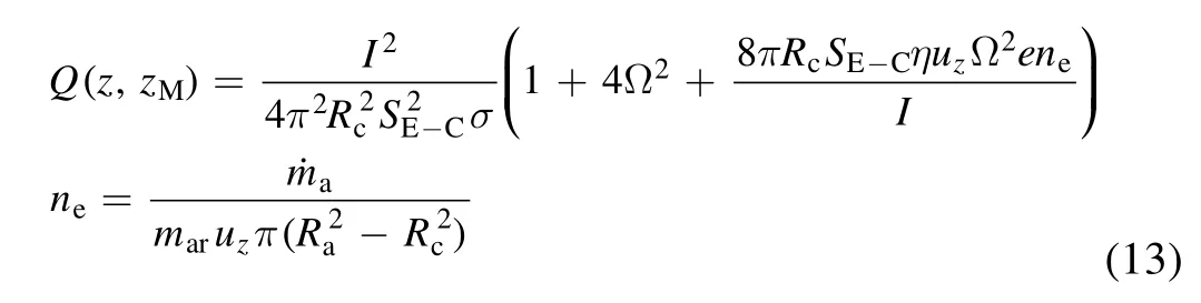
In order to verify the analysis,it is supposed that the current density is mainly concentrated on the cathode erosion sites SE-Cand Joule heating is the same over all operation conditions.Then,the equation(8)can be derived as equation(13).Theηis the parameter increasing with the rise of the SM-C,maris the mass of argon andais anode mass flow rate.According to[38,39],uzand σ are supposed as 5000 m s−1and 10 000 S m−1,respectively.By choosing the condition 1 as reference value,the variation of cathode erosion sites with anode mass flow rate and magnetic field positions can be shown in figure 11.The erosion sites increase with the rise of the SM-Clinearly and decrease with the rise of anode mass flow rate,which is corresponding with the experiment and analysis.
4.Conclusion
In this paper,the relationship of cathode erosion location to applied magnetic field geometry and mass flow rate injection location was examined with graphite cathode material to improve cathode erosion detection.Ten cathodes were the erosion range to spread upstream,as was observed in experiment.

employed in the experiments,corresponding to ten different operation conditions,including different applied magnetic field strengths,applied magnetic field positions,anode propellant mass flow rates and cathode propellant mass flow rates.The data on cathode erosion position related to the influence of these working parameters were incorporated into a theoretical model.Several conclusions that were drawn from the experiment and analysis can be summarized as follows:
(1) The applied magnetic field in a converging/diverging axial configuration can reduce erosion and effectively protect the cathode.When the magnetic field was not applied,the erosion of the cathode was concentrated in one site and the erosion was severe.With the application of additional magnetic field,the erosion of the cathode distributed along the circumferential direction,and the degree of erosion was significantly reduced.
(2) With axial C/D geometry of applied field,the erosion of the cathode was concentrated primarily in the expansion region of the convergent/divergent magnetic field.
(3) The injection of propellant near the anode appeared to reduce erosion of the cathode as a result of a gas layer near the surface of the cathode which would reduce the sputtering of ions to the cathode.
Acknowledgments
This work was supported by the Fundamental Research Program (No.11872093),and we appreciate the helping of Thomas M York,Emeritus Professor at Ohio State University.
猜你喜欢
连云港文学(2022年2期)2022-05-10
Plasma Science and Technology(2021年10期)2021-11-30
Plasma Science and Technology(2021年1期)2021-03-01
现代装饰(2020年7期)2020-07-27
孩子(2019年9期)2019-11-07
散文诗(2017年17期)2018-01-31
延河(2017年7期)2017-07-19
新校园·阅读(2009年8期)2009-10-23
 Plasma Science and Technology2020年9期
- Plasma Science and Technology的其它文章
- Impact of exterior electron emission on the self-sustaining margin of hollow cathode discharge
- Research on the neutralization control of the RF ion micropropulsion system for the‘Taiji-1’ satellite mission
- On the heating mechanism of electron cyclotron resonance thruster immerged in a non-uniform magnetic field
- Study on the influence of the discharge voltage on the ignition process of Hall thrusters
- The plume diagnostics of 30 cm ion thruster with an advanced plasma diagnostics system
- Performance of a 4 cm iodine-fueled radio frequency ion thruster