
Erosion research of CX-2002U carbon composites under low-temperature high-flux hydrogen plasma
2021-02-27 09:17HengxinGUO郭恒鑫ZongbiaoYE叶宗标BizhouSHEN沈必舟JianjunWEI韦建军BoWANG王博YuchuanLUO罗玉川KunZHANG张坤FujunGOU芶富均JianjunCHEN陈建军andBoCHEN陈波
Plasma Science and Technology 2021年2期
Hengxin GUO (郭恒鑫), Zongbiao YE (叶宗标), Bizhou SHEN (沈必舟),Jianjun WEI (韦建军),∗, Bo WANG (王博), Yuchuan LUO (罗玉川), Kun ZHANG (张坤), Fujun GOU (芶富均), Jianjun CHEN (陈建军) and Bo CHEN (陈波)
1 Institute of Atomic and Molecular Physics, Sichuan University, Chengdu 610064, People’s Republic of China
2 Institute of Nuclear Science and Technology,Sichuan University,Chengdu 610064,People’s Republic of China
Abstract The net erosion yield of CX-2002U carbon fiber composites under high-flux low-temperature hydrogen plasma is investigated using a linear plasma device.It is found that the net erosion yield decreases rapidly first, and then tends to saturate with the increase of hydrogen–plasma flux.When the temperature of the sample eroded by hydrogen plasma is above 300°C, the hybridization of electrons outside the carbon atom would change.Then the carbon atoms combine with hydrogen atoms to form massive spherical nanoparticles of hydrocarbon compounds and deposit on the surface at the flux condition of 1.77×10²² m−2·s−1.Under the irradiation of hydrogen plasma loaded with negative bias,the surface morphology of the matrix carbon is changed dramatically.Moreover,the energy dependence of mass loss does not increase in proportion to the increase of hydrogen–plasma energy, but reaches a peak around 20 V negative bias voltage.Based on the analysis of different samples, it can be concluded that the enhancement of energy could make a contribution to chemical erosion and enlarge the size of pores existing on the surface.
Keywords: carbon fiber composites, hydrogen plasma, chemical erosion, redeposition,nanoparticle
1.Introduction
As an important part of tokamak devices, the materials of divertors not only require a highly effective heat-treatment function and a low-level erosion property, but also must bear heat load of about 10 MW·m−2[1, 2].Because of the excellent resistance to thermal shock, graphite is considered as an optional material for divertor-condition plasma.Due to the urgent need for the construction of HL-2M devices,a new generation of tokamak device, the selection of its divertor materials has also been put on the agenda.Compared to graphite materials, the thermal conductivity, thermal expansion, and resistance to heat shock of carbon fiber composites(CFCs)are better.Further,the chemical erosion yield of CFC containing polyacrylonitrile fibers is lower than that of pure graphite materials under the irradiation of high-energy hydrogen plasma [3].Hence, the armor material of the HL-2M divertor plate intends to adopt carbon fiber composites[4].CX-2002U composite is a two-dimensional felt-type CFC which consists of resin and polyacrylonitrile fiber.The resin carbon,acting as a base material,takes 90%of the composite and the polyacrylonitrile fiber, taking 10%, plays a role in reinforcing the composite.With its uniform thermal conductivity and mechanical properties, it has become an alternative material for HL-2M devices [5].
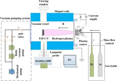
Figure 1.Device diagram of high-flux hydrogen plasma for irradiating sample.
Nevertheless, carbon fiber composites react with hydrogen in the irradiation of hydrogen plasma and could be sputtered when the hydrogen plasma energy exceeds its sputtering threshold.Thus, the erosion, including chemical erosion and physical sputtering caused by hydrogen plasma,should be taken into consideration before it is used in the divertor target.In previous works, the investigation on the erosion of CFC made by K Nakamuraet alunder high heat load revealed that the weight loss of CFCs decreases as the thermal conductivity increases at high bulk temperatures[6, 7].The investigatory result of sputtering yields under the irradiation of high-energy plasma [8, 9] indicated that the sputtering yields of CFCs increase with the energy in the range of 50–100 eV.Moreover, F.Scaffidi-Argentinaet alfound that the eroded carbon would redeposit back on the irradiated surface with the irradiation of low-energy hydrogen plasma through simulating the plasma disruption [10, 11].Meanwhile, reducing the retention of hydrogen in carbon materials[12,13]under the irradiation of hydrogen plasma is an unsolved issue.In addition, the formation of hydrocarbon compounds in the process whereby hydrogen plasma erodes carbon materials is still under exploration,with much interest by many scientists [14–16].
Although much work has been done on the interaction between hydrogen plasma and CFC composites, there is relatively little work concerning the erosion of carbon fiber composites with high-flux hydrogen plasma at low temperatures and analyzing the underlying dynamic process and mechanism.Therefore, it is quite necessary to investigate the morphological and structural development of CX-2002U composites on the condition of hydrogen plasma before the material is used in the HL-2M device.To address these problems,CX-2002U composites irradiated by different highflux hydrogen plasmas have been investigated in this work,with a focus on the effect of different-energy hydrogen plasmas on the samples.At the same time, our work can provide a reference as to whether CX-2002U composite materials can be applicable to HL-2M divertors.
2.Experiment
The CX-2002U carbon fiber composite produced by Tokyo Tanso Kogyo was cut into square blocks(1.5 cm×1.5 cm ×0.5 cm).Since samples were not protected during the process of cutting and transportation, there were many impurities,such as oil stains, debris, and dust on their surfaces.In order to remove these impurities, each sample, in turn, was ultrasonically cleaned with volatile acetone, alcohol, and deionized water for 20 min.Before the sample was irradiated by hydrogen plasma, it would stay in the blast oven with air inside at 50°C for seven hours to remove residual water for error reduction when weighing the samples.
Hydrogen plasma is generated by a three-cathode cascaded direct current (DC) discharge in the experiment.According to the research on plasma characteristics [17], the density, energy, and the size of plasma beam spots could be adjusted by DC power supply (90–240 A), magnetic field(0–0.45 T),and gas flux(0–5000 sccm),respectively,into the chamber.As shown in figure 1, the tungsten needle rapidly rises to high temperatures with high voltages across theneedle, and emits electrons during the process of discharge.Then the argon introduced by vent pipe is ionized firstly.The ionized argon ions and electrons will increase the probability of hydrogen ionization by ramping up the number of collisions with hydrogen [18, 19].When the external absorbed energy of the hydrogen atom is up to 13.6 eV, the hydrogen gas will be ionized.Then the hydrogen plasma will be in Larmor motion along the direction of the magnetic field due to the combined action of Lorentz force and initial velocity.The flux of hydrogen plasma could be detected by Langmuir probe, and relevant experimental parameters are shown in table 1.

Table 1.Experimental conditions corresponding to different-flux hydrogen plasmas.
Each sample was placed on a substrate that was 0.39 m away from the plasma source.Furthermore, the chemical erosion of the CX-2002U composite caused by hydrogen plasma was studied based on the preceding experimental parameters.Furthermore, a negative electric potential difference by bias power supply was applied across the chassis to analyze the energy dependence of the erosion, and the microstructure of each irradiated sample was observed through scanning electron microscopy (SEM).
3.Experimental results and discussion
3.1.Effect of flux on erosion
The energy of various particles in hydrogen plasma detected by Langmuir probe in the experiment is about 1 eV,which is far below the physical sputtering threshold of carbon-based materials (∼35 eV).In the meantime, the chemical erosion caused by hydrogen plasma is a dominated process as compared with physical sputtering.Therefore, the model established by J Rothet al[20–22] shown in figure 2 is used to explain the chemical erosion process in this work.The net erosion yield of the irradiated sample is closely related to the mass loss, irradiated time, and hydrogen–plasma flux.The expression [23] is as follows:
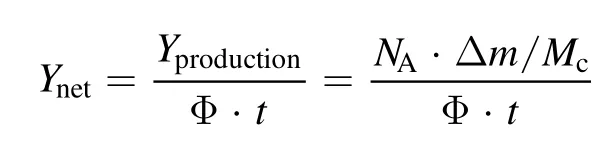
whereYnetis the net erosion yield,Yproductionis the net erosion production,NAis the Avogadro constant,Δmis the mass loss of each sample,Mcis the molar mass of carbon,Φ is the flux of the hydrogen plasma beam, andtis the irradiated time.Therefore, the net erosion yield is proportional to the net erosion production with the same time length and same flux of irradiation.
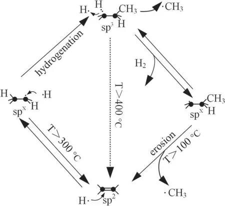
Figure 2.Simple model of chemical erosion described by J Roth et al.
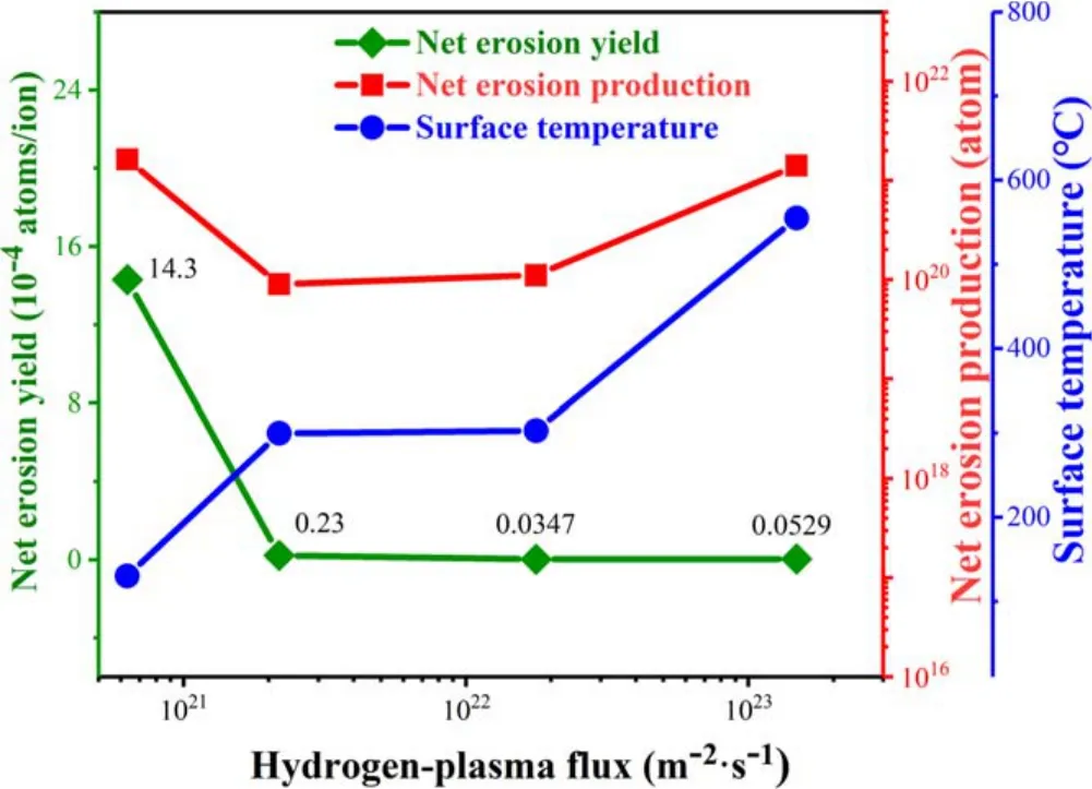
Figure 3.Variation trend of the net erosion yield, temperature, and net erosion production with increasing flux of hydrogen plasma.
With the transformation of interactional-particle amount,the temperature of the sample would increase with plasma flux.Therefore, a set of thermocouples is placed on the back of the substrate to detect the temperature of different samples in experiments.The variation trend of temperature and the net erosion yield with the increase in plasma flux has been shown in figure 3.The temperatures of samples are 130°C, 300°C,303°C, and 555°C, respectively.When the flux of hydrogen plasma increases from 6.32×10²⁰to 2.18×10²¹m−2·s−1,the net erosion yield of the sample quickly decreases from 1.43×10⁻³atoms/ion to 2.3×10⁻⁵atoms/ion.Then the net erosion yield stays around 0.4×10⁻⁵atoms/ion when the flux is located between 2.18×10²¹and 1.77×10²²m−2·s−1.It has been revealed that the net erosion yield of the sample is close to saturation when hydrogen plasma flux approaches 1.77×10²²m−2·s−1.

Figure 4.SEM images of (a) original sample, (b)–(e) sample irradiated by different-flux hydrogen plasmas (6.32×10²⁰, 2.18×1021,1.77×1022, and 1.48×10²³ m−2·s−1, respectively).
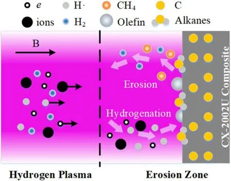
Figure 5.Chemical erosion on sample’s surface.
In terms of carbon-based materials,the erosion caused by hydrogen plasma would generate·CH3,which could combine with·H in hydrogen plasma to form CH4and be released from the surface, when the temperature is between 100°C and 300°C [21], as shown in figure 5.It could result in the increase of the net erosion yield.Thus, the value of the net erosion yield at 130°C gets to maximum, though the flux of hydrogen plasma is minimum.When the temperature reaches 300°C, the bond cleavage would occur to the outer shell electrons of the carbon atom in the a-C: H structure and the electrons would be re-hybridized into the sp2configuration and form a carbon–carbon double bond with another carbon atom.The simple model of chemical erosion shown in figure 2 indicates that it would lead to the formation of olefinic hydrocarbons on the surface of the sample.Hence, the net erosion yield would dramatically decrease with the flux of hydrogen plasma increasing, then tend toward saturation,which is consistent with the chemical erosion of graphite[20, 22, 24].Besides, the erosion efficiency increases exponentially with the substrate temperature [15],which is shown in figure 3, where the net erosion production continues to increase with temperature when temperature is above 300°C.As the net erosion yield tends toward saturation, it could be concluded that both the yield of redeposition and the erosion of carbon would be amplified by the increase in plasma flux,and this could keep a dynamic balance [11].
In order to deeply demonstrate the aforementioned phenomena caused by hydrogen plasma,the surface morphology of each sample is analyzed by SEM, as shown in figure 4.Figure 4(a) is a set of SEM images of the original sample in which the obvious scratches caused by mechanical cutting can be clearly seen.After hydrogen-plasma irradiation with different fluxes for 30 min, the scratches gradually disappear,and then the polyacrylonitrile fibers become much clearer.Since CH4is produced at temperatures no higher than 300°C,the SEM images show only that the fiber is broken down and detached.Moreover, the microstructure of the sample shown in figure 4(d) changes a lot while the temperature is higher than 300°C.It is scattered with spherical nanoparticles on the surface.As shown in figure 6,the energy dispersive spectrum of these particles show that it is mainly composed of carbon,which means that these particles should be redeposited carbon dust.Since spherical surface has the lowest potential energy,the C–C bond combines with the hydrogen atom to form spherical olefin compound in the gas phase and deposits on the surface of the sample[25–28],resulting in the decrease of the net erosion yield at 303°C.Moreover, the change in the way of electrostatic bonding would absorb a large amount of heat during irradiation[29],which leads to the stabilization of temperature at the flux of 1.77×10²²m−2·s−1.Combined with the foregoing conclusion that the net erosion yield tends to saturate under this condition, this demonstrates that the reaction of hydrogen plasma and carbon is a dynamic process of erosion-deposition equilibrium when the temperature is higher than 300°C.What is more, as the flux increases to 1.48×10²³m−2·s−1, it is easy to see that the deposited particles are concentrated in gully regions on the surface in figure 4(e).In addition,there are obvious erosion signs on the surface.Therefore, it could be predicted that the net erosion yield is still saturated, and the erosion caused by hydrogen plasma might be very dramatic when the hydrogen-plasma flux is above 1023m−2·s−1.
In addition, the hydrogen-plasma irradiation would change the structural characteristics of the sample surface[30,31].As shown in figure 7,the peak position of the(002)crystal plane shifts to the right by about 0.15°as compared to the original sample.Further, the intensity of the diffraction peak is much reduced.This indicates that the crystallinity of the sample is weakened and the lattice structure of the sample would be distorted at this time.As described previously, a new compound, olefin hydrocarbons, would form in the gas phase and deposit on the sample’s surface during the erosion of carbon materials by hydrogen plasma.The new deposited hydrocarbon might finally affect the x-ray diffraction pattern result on the sample [32].Moreover, at the beginning of irradiation, the temperature difference between the surface and the inside of the sample might change the residual stress of the sample and cause the distortion of crystal lattice [33].
3.2.Effect of energy on erosion
To explore the influence of plasma energy on the surface morphology of samples, negative bias is applied to the back of the substrate to adjust the energy when the flux of the hydrogen plasma is 1.48×10²³m−2·s−1.Firstly, the impact of the plasma fluence on the sample should be studied with the same energy.When the sample will be irradiated for 10 min by hydrogen plasma with 20 V negative bias applied,as shown in figure 8, the surface of polyacrylonitrile fiber would form a villus-like structure and substantial carbon dust is attached on the top of each spicule structure.As compared to polyacrylonitrile fiber, the pore size of matrix carbon is larger.This indicates that the reinforcing fiber is more resistant to hydrogen erosion than resin matrix carbon.While the irradiation time is extended to 30 min,it would be easy to find that the pore size of the sample shown in figure 9(b)becomes larger.The structure is more stab-like, which means that the erosion caused by hydrogen plasma is more serious.
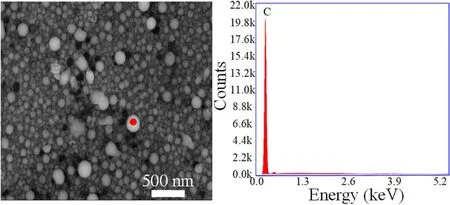
Figure 6.EDS spectrum of deposited particles.
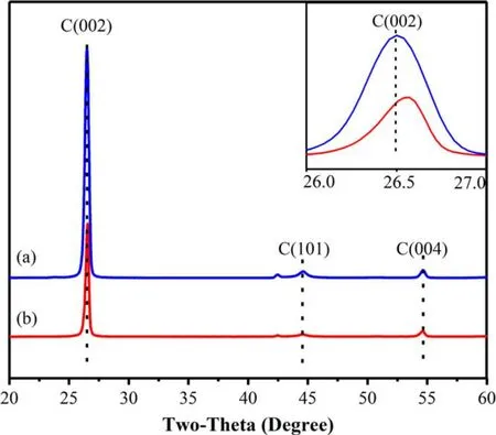
Figure 7.X-ray diffraction patterns of samples (a) before and (b)after exposure to hydrogen plasma.
Then the influence of plasma energy below sputtering threshold on a sample with the same fluence is put under investigation.As shown in figure 9(a), while a 10 V negative bias voltage is applied across the substrate, the amount of carbon dust deposited on the surface decreases greatly, as compared with figure 4(e).With the negative bias approaching 20 V,substantial pores come to appear on the surface,and some cluster particles are attached to the surface.These microscopic pores form a stab-like structure layer.This structure could increase the contact area with hydrogen plasma to enhance the erosion caused by hydrogen plasma.When the negative bias voltage is about 30 V, the size of pores becomes larger than those shown in figure 9(b) and reaches the micron level.Some carbon dust eroded by hydrogen plasma adheres to the inner wall of cracks and pores.Therefore, the change in the morphology of samples becomes more obvious with the increase in the plasma energy.

Figure 8.SEM images with different magnifications: (a) polyacrylonitrile fiber, (b) resin carbon irradiated by hydrogen plasma with 20 negative bias and flux of 1.48×10²³ m−2·s−1 for 10 min.
However, the change of the samples’ mass loss is obviously different from the trend of morphology change.Figure 10 reveals that the mass loss of the irradiated sample without bias voltage is higher than that of the irradiated sample with 10 and 30 V negative bias voltage,and the value reaches the maximum at 20 V negative bias voltage.The discussion in section 3.1 shows that the chemical erosion and the redeposition of carbon reach a dynamic equilibrium when the flux is 1.48×10²³m−2·s−1because hydrogen plasma that is accelerated by the externally applied negative bias voltage can increase the probability of methane ionization,which would result in the formation of deposited carbon particles [34].Moreover, the deposition could be enhanced with the increase of negative bias[35].Therefore,the process might be the cause of the decrease of mass loss with negative bias increasing.The result is different from previous results[21, 36], namely that the mass loss does not increase monotonously with the growth of hydrogen plasma energy,whereas it is consistent with the conclusion described by Q Zhaoet althat the peak value of mass loss appears around at 20 V negative bias voltage [37].The mass loss tendency under different bias voltages is irregular but reproducible,but its inside mechanism is still not clear right now and needs further investigation in the next-step experiment.
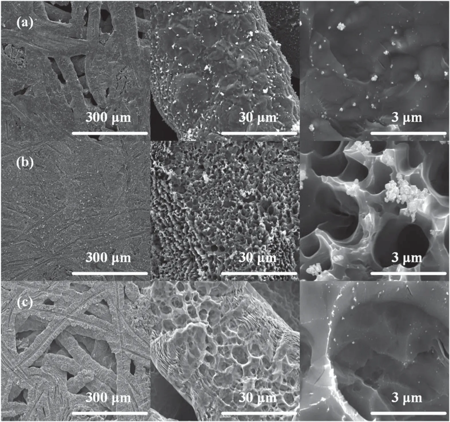
Figure 9.(a)–(c) SEM images with different magnifications.The sample is irradiated by hydrogen plasma beam with 10, 20, and 30 V negative-bias voltage, respectively, applied across for 30 min.
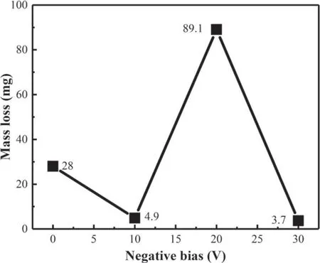
Figure 10.Mass loss of the sample irradiated by hydrogen plasma of different energy.
4.Conclusions
Carbon fiber composite materials have become a potential candidate for divertor targets due to superior thermal shock resistance, high melting point, and high thermal conductivity.However, chemical erosion induced by high-flux and low-temperature hydrogen plasma would shorten the lifetime of carbon materials, so this needs detailed research before these materials are applied as divertor components.In this paper, the chemical erosion of CX-2002U composite caused by different-flux hydrogen plasma is explored by simulating the plasma condition of the divertor.In addition,the chemical erosion of the material caused by differentenergy hydrogen plasmas is researched by adding negative bias to the substrate.The conclusions can be summarized as follows:
(1) The net erosion yield decreases rapidly with the increase of hydrogen plasma flux.It approaches saturation when the flux is close to 1.77×10²²m−2·s−1,which means the chemical erosion and redeposition have reached a balance,while the net erosion production of the sample continues to increase under the irradiation of higher-flux hydrogen plasma.Although the phenomena would change surface morphology, the basic structure of each sample has not transformed.
(2) The changing tendency of mass loss does not increase monotonically as the energy of hydrogen plasma increases, but reaches a peak value when substrate is added to 20 V negative bias.It would form a nanometer-size burr-like layer on the surface at this time, which might facilitate the erosion caused by hydrogen plasma.The nanostructure could have more potential applications in battery anode materials, ion transportation,and mass transfer of particulate materials with the characteristic of high specific surface area.
Acknowledgments
This work is supported by National Natural Science Foundation of China (No.11875198), Young Scientists Fund of National Natural Science Foundation of China (No.11905151), Fundamental Research Funds for the Central Universities of China (No.2019SCU12072), and the China Postdoctoral Science Foundation (No.2019M663487).
猜你喜欢
Chinese Physics B(2022年10期)2022-10-26
科海故事博览·上旬刊(2022年5期)2022-05-17
浙江人大(2022年4期)2022-04-28
Plasma Science and Technology(2021年11期)2021-11-30
孩子(2021年2期)2021-02-25
考试与评价·高二版(2020年6期)2020-09-10
杂文选刊(2020年1期)2020-01-10
读与写·教育教学版(2017年10期)2017-11-10
速读·下旬(2017年4期)2017-06-20
校园英语·下旬(2016年9期)2016-11-07
 Plasma Science and Technology2021年2期
- Plasma Science and Technology的其它文章
- Effect of edge turbulent transport on scrapeoff layer width on HL-2A tokamak
- An investigation on improving the homogeneity of plasma generated by linear microwave plasma source with a length of 1550 mm
- Spatio-temporal evolution characteristics and pattern formation of a gas–liquid interfacial AC current argon discharge plasma with a deionized water electrode
- Turbulent boundary layer control with a spanwise array of DBD plasma actuators
- Plasma activation towards oxidized nanocarbons for efficient electrochemical synthesis of hydrogen peroxide
- Spatio-temporal evaluation of Zr plasma parameters in a single-beam-splitting double-pulse laser-induced plasma