
Study of the influence of discharge loop parameters on anode side on generation characteristics of metal plasma jet in a pulsed vacuum discharge
2021-06-21 02:00WenjunZHANG张文俊WenzhengLIU刘文正JiaTIAN田甲YongjieGAO高永杰XitaoJIANG姜希涛andPengxiangLIU刘鹏翔
Plasma Science and Technology 2021年6期
Wenjun ZHANG(张文俊),Wenzheng LIU(刘文正),Jia TIAN(田甲),Yongjie GAO(高永杰),Xitao JIANG(姜希涛)and Pengxiang LIU(刘鹏翔)
School of Electrical Engineering,Beijing Jiaotong University,Beijing 100044,People’s Republic of China
Abstract In a pulsed vacuum discharge,the ejection performance of a metal plasma jet can be effectively improved by preventing charged particles from moving to the anode.In this paper,the effects of resistance and capacitance on the anode side on the discharge characteristics and the generation characteristics of plasma jet are investigated.Results show that the existence of a resistor on the anode side can increase the anode potential,thereby preventing charged particles from entering the anode and promoting the ejection of charged particles along the axis of the insulating sleeve nozzle.The application of a capacitor on the anode side can not only absorb electrons at the initial stage of discharge,increasing the peak value of the cathode hump potential,but also prevent charged particles from moving to the anode,thereby improving the ejection performance of the plasma jet.In addition,the use of a larger resistance and a smaller capacitance can improve the blocking effect on charged particles and further improve the ejection performance of the plasma jet.Results of this study will provide a reference for the improvement of the ejection performance of plasma jets and their applications.
Keywords:metal plasma jet,pulsed vacuum discharge,discharge loop parameters on anode side,charged particles movement
1.Introduction
In a low-current pulsed vacuum discharge,a supersonic(~104m s-1)metal plasma jet can be generated by ablating the cathode material[1–7],which can be applied to ion implantation technology,extraction of highly ionized ion beams and pulsed plasma thrusters[8–14].
A great deal of research on the generation characteristics of vacuum metal plasma jets has been done.M.Keidar,C.Wang and J.Y.Geng studied the effect of an external magnetic field on a plasma jet.Results showed that the radial expansion of a plasma jet decreased considerably and the speed increased significantly with the increase of magnetic field[15–18].The research of J.E.Polk showed that the kinetic energy of arc plasma increased when the plasma was accelerated electrostatically[19].J.Lun investigated the use of conically shaped convergent cathode surface profiles in a thruster design.Results showed that modifying the profile of the cathode face can affect the plasma jet’s plume distribution[20].Through optimization of electrode parameters and reasonable setting of insulating materials,W.Z.Liu improved the plasma density and propagation velocity of a plasma jet[21,22].However,in these studies,the anodes are all directly grounded.
In the process of studying ejection performance of vacuum metal plasma jets,it was found that most charged particles enter the anode when it is directly grounded,which leads to a decrease in the ejection performance of a plasma jet ejected along the axis of an insulating sleeve nozzle,including plasma density and propagation velocity.In order to prevent charged particles from entering the anode,J.Tian proposed a fully insulated anode structure[23].However,discharge difficulty increased and plasma production was reduced.Therefore,to further improve the ejection performance of plasma jets,in this study,the effects of the resistance and capacitance of the anode side on the discharge characteristics and generation characteristics of plasma jets are investigated.Results of this study will provide a reference for the improvement of the ejection performance of plasma jets and their applications.
2.Experimental setup
2.1.Experimental system
The schematic of the pulsed vacuum discharge experimental system is shown in figure 1.It is mainly composed of a vacuum chamber,a discharge electrode,a pulse discharge circuit,an electrical parameter measurement system and a Langmuir probe measurement system.In this study,all experiments were performed in a closed,grounded vacuum chamber.Before each discharge,pressure in the vacuum chamber was controlled at about 10-4Pa by a mechanical pump and an oil diffusion pump.Discharge phenomena between the cathode and anode were observed through a glass window on the side of the vacuum chamber.Discharge voltage between the cathode and anode was measured by a high-voltage probe(Tektronix P6015 1000X).Discharge currents flowing through the cathode side(cathode current)and anode side(anode current)were measured simultaneously by using two identical Rogowski coils(2000 V/5 A).The measurement positions of the high-voltage probe and the Rogowski coils are shown in figure 1.
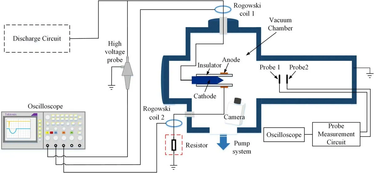
Figure 1.Schematic of the experimental pulsed vacuum discharge system.
2.2.Electrode structure and discharge loop
A schematic of the electrode structure and parameters is shown in figure 2.It is mainly composed of three parts:a cathode,an insulating sleeve and an anode.One end of the metallic lead cathode is cylindrical in shape,the other end is a cone with a cone angle of 60°.The cone tip is located at the center of the anode.The insulating sleeve,made of polytetrafluoroethylene(PTFE),is sleeved on the outside of cathode and is in close contact with the cathode.The anode is an aluminum ring and it is in close contact with the insulating sleeve.
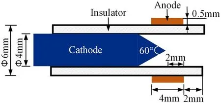
Figure 2.Electrode structure and parameters.
The schematic diagram of the two discharge loops is shown in figure 3.They are an anode non-resistor discharge loop(ANRDL)and an anode resistor discharge loop(ARDL).In comparison,in the ARDL,the anode is grounded via a resistor.Through comparative analysis of discharge characteristics when the two discharge loops are used,respectively,the influence that the resistor on the anode side in discharge loop had on the generation characteristics of the metal plasma jet was explored.
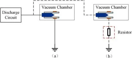
Figure 3.Schematic of the discharge loops.(a)ANRDL,(b)ARDL.
2.3.Discharge circuit
The schematic diagram of the single-pulse discharge circuit is shown in figure 4.The discharge circuit was composed of a main discharge circuit and a trigger system.The main discharge circuit was a voltage-doubler circuit,which charged the main discharge capacitor C2 to 0–20 kV.Then,the trigger system was initialized to cause a three-point gap breakdown,and the voltage of capacitor C2 was applied between the cathode and the anode to cause a discharge between them.
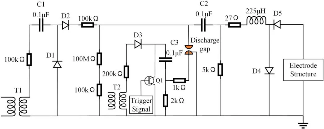
Figure 4.Schematic of the single-pulse discharge circuit.
2.4.Langmuir probe measurement system
In this study,an improved Langmuir single-probe system and a dual-probe system were used to measure the plasma density and propagation velocity of plasma,respectively.The schematic of the measurement system is shown in figure 5;and this method has been used for plasma measurement before[21–23].The adopted cylindrical Langmuir probe has a diameter of 1 mm and a length of 5 mm.
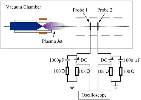
Figure 5.Schematic of the Langmuir probe measurement system.
When measuring the plasma density,a Langmuir single probe 1 was placed 145 mm from the discharge electrode.First,a DC bias was applied to probe 1,and then the electronic current flowing on the probe during each discharge was recorded.The peaks of electronic currents for 10 discharges were recorded,and the average value of 10 discharges was taken as the electronic current value at a DC bias voltage.The V–lnI characteristic curve of the probe electron current was drawn for the entire process by changing bias voltages and repeated recording.From this V–lnI curve,the saturation electron current Iesand the space potential Vspof the plasma were obtained.In this study,electrons follow the Maxwell distribution and electron current decreases exponentially with the decrease of bias voltage.The relationship between the electron current(Ie)on the probe and the bias voltage(VB)can be expressed as

Here,e is the electron charge,kBis the Boltzmann constant and Teis the electron temperature.So,the electron temperature Tecan be calculated from the above equation.
The saturated electron current Iesis calculated as
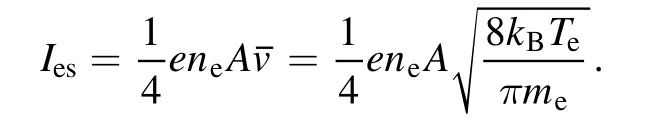
Here,neis electron density,A is the collection area of the Langmuir probe,v is the speed of electron thermal movement and meis electron mass.So,the electron temperature Tecan be calculated from the above equation.
Therefore,the electron density at the measurement position can be expressed as
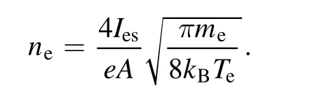
From the definition of plasma quasi-neutrality,the plasma density is np=ne=ni.Where niis the ion density.
When measuring the propagation velocity of plasma,another identical single probe 2 was arranged at a position x=25 mm away from the probe 1 in the axial direction away from the electrode.The same DC bias was applied to the two probes at the same time,and the time interval between the peaks of two probe electron currents was measured.Then the propagation velocity of plasma was calculated based on v=x/Dt.
3.Comparison of plasma jet generation
In a pulsed vacuum discharge,many charged particles can be generated by ablating the cathode metal materials.Some of these charged particles will move to anode under the action of space electric field,forming circuit current.The other part is ejected along the axial direction of the insulating sleeve nozzle under the action of hump potential to form a plasma jet.It is inferred that by preventing charged particles from moving to the anode,the ejection performance of a metal plasma jet can be effectively improved[24].Therefore,in this section,firstly,through a vacuum discharge experiment,the effects that the resistor on the anode side has on the discharge characteristics of an electrode are explored.Secondly,Matlab/Simulink simulation software is used to simulate the electrode discharge process and the discharge characteristics of an electrode equivalent circuit with or without a resistor on the anode side are compared and analyzed.Finally,the basic parameters of the plasma jet are measured by using an improved Langmuir probe method.
3.1.Discharge characteristics
During the experimental study,for the two discharge loops above,the resistance in the ARDL was set to 33 Ω.The same voltage of 12 kV was applied to the main capacitor C2,and 20 discharges were carried out,among which representative discharge voltage and current waveforms are shown in figure 6.Some of the discharge parameters are shown in table 1.
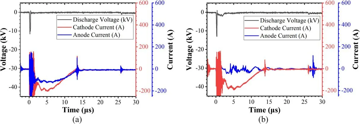
Figure 6.Waveforms of discharge voltages and discharge currents with different discharge loops.(a)ANRDL,(b)ARDL.
In table 1,the initial discharge voltage,the peak value and period of currents were obtained by averaging the measurement results of 20 discharges,and the maximum deviation is not more than 3%,2% and 4%,respectively,and f1 represents the ratio of the peak of anode current to the peak of cathode current.According to table 1,under the same discharge voltage,compared with the ANRDL,by using the ARDL,the initial discharge voltage slightly increases,but f1 is greatly reduced.
Table 1.Discharge parameters with different discharge loops.
3.2.Simulation modeling of the discharge loop
According to the discharge phenomenon between the cathode and the anode,the electrode can be equivalent to an equivalent circuit constituting one main branch and two branch circuits,as shown in figure 7.In figure 7,the cathode is the main branch,and the two branches are the cathode–anode branch(branch 1)and the cathode–plasma jet branch(branch 2)[25].A resistor R was connected in series between the branch 1 and the ground,and was set to 0 Ω and 1 Ω,respectively.The simulated discharge voltage and discharge current waveforms obtained in the two cases are shown in figure 8.
Figure 8.Simulated waveforms of the discharge voltages and discharge currents with different discharge loops.(a)R = 0 Ω,(b)R = 1 Ω.
Comparing figures 6 and 8,it can be seen that the simulated discharge voltage and current waveforms are consistent with the actual ones.Therefore,the model of the discharge loop established in this paper can be used to simulate the actual changes of discharge loop parameters.In figure 8,the discharge voltage is the voltage between the main branch voltage(point A in the figure 7)and the ground.The total current is the current flowing through the main branch of the electrode equivalent circuit;that is,the current flowing through point A shown in figure 7.Branch 1 current is the current flowing through branch 1 of electrode equivalent circuit,;that is,the current flowing through point B shown in figure 7.Branch 2 current is the current flowing through branch 2 of the electrode equivalent circuit;that is,the current flowing through point C shown in figure 7.It can be seen from figure 8 that,compared with R=0 Ω,when R=1 Ω,the peak of branch 1 current is significantly reduced and the peak of the branch 2 current is significantly increased.
Figure 7.Schematic of the simulation model of the discharge loops.
Based on the analysis above,it can be concluded that the resistor in the ARDL can limit the anode current and increase the plasma jet current.Accordingly,it is speculated that a plasma jet with a better ejection performance will be generated when using an ARDL.
3.3.Generation characteristics of plasma
In order to verify the speculation in section 3.2,the discharge phenomena and plasma generation of two discharge loops are analyzed in this section.Discharge phenomena taken by the same camera with an exposure time of 0.5 s when using the two discharge loops are shown in figure 9.
It can be seen from figure 9 that plasma jets ejected along the axial direction of the insulating sleeve are generated near the insulating sleeve nozzle by using both discharge loops.According to figure 9(a),the anode surface has bright luminescence when using the ANRDL.Combined with the anode current data in table 1,analysis shows that most of plasma generated by discharge moves to the anode,and only a small part is ejected along the axial direction of the insulating sleeve nozzle to form a plasma jet.It can be seen from figure 9(b)that,compared with the ANRDL,when using the ARDL,the luminescence of the anode surface is obviously weakened,the plasma ejected along the axial direction of insulating sleeve nozzle is obviously increased and the length of plasma jet increases from 5 mm to 10 mm.Analysis shows that when charged particles moving to the anode under the action of space electric field pass through the resistor,a large voltage drop forms at both ends of the resistor.Since one end of the resistor is grounded,the potential of the anode connected to the other end of the resistor is raised.The increase of anode potential prevents subsequent charged particles from reaching the anode and ultimately limits the movement of charged particles to the anode.
Figure 9.Discharge phenomena with different discharge loops.(a)ANRDL,(b)ARDL.
Figure 10(a)shows the waveforms of electron currents in the case of the ANRDL.According to figure 10(a),the propagation velocity of the plasma jet when the ANRDL was used is calculated to be 7.6×10³m s-1.Figure 10(b)shows the V–lnI characteristic curve obtained by gradually increasing the DC bias applied to probe 1 in a pulsed vacuum discharge.The plasma density calculated according to the V–lnI curve is 2.2×10¹⁶m-3.Similarly,the same method was used to obtain the plasma density and propagation velocity of the plasma jet when the ARDL was used.Specific plasma parameters are shown in table 2.
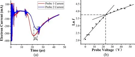
Figure 10.(a)Waveforms of electron currents.(b)V–lnI characteristic curve.

Table 2.Plasma parameters with different discharge loops.
In order to investigate the ejection performance of the plasma jet generated by different discharge loops,a singleprobe system was used to measure the spatial distributions of plasma densities.The schematic of measurement positions is shown in figure 11 and the measurement results are shown in figure 12.Specific plasma parameters are shown in table 2.
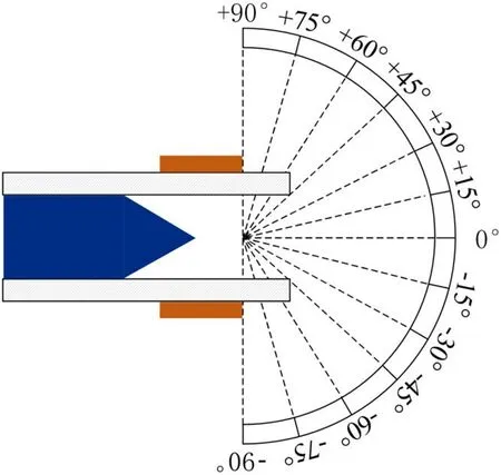
Figure 11.Measurement positions of plasma density.

Figure 12.Angular distributions of plasma densities with different discharge loops.(a)ANRDL,(b)ARDL.
It can be seen from figure 12 that with the continuous increase of the measuring position angle,plasma density tends to decrease.When using the ARDL,the peak plasma density deviates from the axial position(0°).Compared with ANRDL,when using the ARDL,the peak plasma density increases by 72%.Analysis shows that the existence of the resistor can prevent charged particles from moving to the anode,causing more charged particles to eject along the axial direction of the insulating sleeve nozzle,thereby increasing plasma density.
4.Parameter optimization
Based on the ARDL,in this section,the influences that the resistances and capacitances on anode side had on discharge characteristics and generation characteristics of plasma jet are explored.
4.1.Resistance of the resistor
During the experiment,when using the ARDL shown in figure 3(b),resistors with different resistances were selected.Discharge characteristics were tested when the resistances were 33 Ω,100 Ω,1 kΩ,100 kΩ,1 MΩ and 1 GΩ,respectively,and parameters are shown in table 3.In order to compare the discharge characteristics with different resistances more clearly,the data under the condition of R=33 Ω adopt the same experimental data as the ARDL discharge in section 3.1.

Table 3.Discharge parameters with different resistances.
It can be seen from table 3 that,when the resistance increases,the initial discharge voltage increases,the peak of cathode current decreases and the period increases.Both the peak and period of the anode current decrease significantly with the increase of resistance.Analysis shows that the increase of resistance increases the time constant τ of the discharge loop and slows down the energy release rate of the energy storage capacitor C2.The increase of initial discharge voltage means an increase of discharge difficulty.However,as the resistance increases,f1 becomes smaller.It is shown that,as the resistance increases,the amount of plasma moving to the anode becomes smaller and smaller,and the blocking effect on charged particles becomes better and better.
The discharge phenomena under different resistance conditions are shown in figure 13.It can be seen from figures 13(a)–(d)that the greater the resistance is,the weaker the anode luminescence is,and the longer the length of plasma jet ejected along the axis of the insulating sleeve nozzle is.It can be seen from figures 13(e)–(f)that with the continuing increase of resistance,the luminescence on the anode surface disappears;however,the length of the plasma jet does not continue to increase but becomes shorter than figure 13(d).In addition,it is found that when the resistances are small,the ejection direction of plasma jet deviates from the axial direction and the direction deviating from the axial direction is random,as shown in figures 13(a)and(b).

Figure 13.Discharge phenomena with different resistances.(a)R=33 Ω,(b)R=100 Ω,(c)R=1 kΩ,(d)R=100 kΩ,(e)R=1 MΩ,(f)R=1 GΩ.

Table 4.Plasma parameters with different resistances.
Table 4 shows some of the specific plasma parameters for different resistances.Measurement results show that when the resistance increases from 0 Ω to 100 kΩ,the plasma density,propagation velocity and the length of plasma jet are increased by 2.2 times,1.1 times and 2.8 times,respectively.The data under the condition of R=0 Ω adopt the same experimental data as the ANRDL discharge in section 3.3.When R continues to increase from 100 kΩ to 1 GΩ,compared with R=100 kΩ,the plasma density,propagation velocity and length of plasma jet all decrease.Analysis shows that increasing the resistance on the anode side can further prevent the charged particles from moving to the anode,but the excessive resistance hinders the escape of electrons at the initial stage of the discharge,which is not conducive to the establishment of a cathode hump,and ultimately affects the improvement of the ejection performance of the plasma jet.When the resistances are small,the ability to prevent charged particles from moving to the anode is limited,and many charged particles still move to the anode.Due to the randomness of the distribution of charged particles moving to the anode surface,the luminous intensity near the anode surface is not uniform.In addition,since the plasma moving to the vicinity of anode exhibits a positive spatial potential as a whole and the plasma ejected from the nozzle of insulating sleeve also exhibits a positive polarity as a whole,therefore,the plasma jet ejects in the opposite direction where the luminous intensity is smaller.The ejection direction of plasma jet deviates from the axial direction so that the peak plasma density is not in the axial direction of the insulating sleeve,which is not conducive to the improvement of directional ejection performance of the plasma jet.Therefore,there is an optimal resistance to obtain the optimal ejection performance.
4.2.Capacitor on the anode side
Based on the discussion in section 4.1,when using the ARDL,the existence of the resistor hinders the escape of electrons at the initial stage of discharge,which is not conducive to the establishment of a cathode hump.In order to not only prevent charged particles from moving to the anode,but also not affecting the establishment of a cathode hump,in this section,the influence that the capacitor on the anode side in the discharge loop has on the generation characteristics of the metal plasma jet is explored.The schematic diagram of anode capacitor discharge loop(ACDL)is shown in figure 14.The difference from the ARDL is that the resistor is replaced by a capacitor in the ACDL.

Figure 14.Schematic of the ACDL.
Table 5 shows some of discharge parameters when the capacitances are 10 000 pF,1000 pF,100 pF and 10 pF,respectively.According to table 5,with the decrease of capacitance from C=10 000 pF to C=10 pF,f1 decreases in sequence.
The discharge phenomena with different capacitances are shown in figure 15.It can be seen from figure 15 that as the capacitance decreases,the length of the plasma jet first increases and then decreases.Compared with the use of the ANRDL in section 3.3,when C=100 pF,the length of the plasma jet is increased by four times.
Figure 14.Schematic of the ACDL.
Table 6 shows some specific plasma parameters by using an ACDL with different capacitances.It can be seen from table 6 that compared with the use of the ANRDL in section 3.3,when C=100 pF,the peak plasma density and propagation velocity are increased by 3.1 times and 1.2 times,respectively.
It is found that electrons can be absorbed by the capacitor at the initial stage of discharge,which helps the establishment of the cathode hump,and the cathode hump plays a vital role in the ability of maintaining discharge.When the capacitor is fully charged,it is disconnected,blocking the arrival of subsequent electrons and making the generated charged ions eject along the axial direction of the insulating sleeve nozzle.The decrease of capacitance is beneficial for charging and discharging processes.However,if the capacitance is too small,the ability of the capacitor to absorb electrons will be affected,which will affect the establishment of a cathode hump.
Based on the discussion above,it can be concluded that the application of a capacitor on anode side can not only prevent charged particles from moving to the anode,but also absorb electrons at the initial stage of discharge,which increases the peak value of the cathode hump potential.Therefore,using an ACDL can improve the ejection performance of a plasma jet better than an ARDL in a pulsed vacuum discharge.
5.Conclusions
In this paper,a method that can improve the ejection performance of plasma by controlling the amount of charged particle absorption over time by using a resistor or a capacitor on the anode side,influencing the establishment process of a cathode hump,is proposed.Specific conclusions are as follows:
(1)In a pulsed vacuum discharge,by changing the discharge loop parameters on the anode side,the ejection performance of a metal plasma jet can be effectively improved.
(2)The existence of a resistor in the ARDL can increase anode potential,prevent charged particles from moving to the anode and make more charged particles eject along the axis of the insulating sleeve nozzle.It is better to use a resistor with larger resistance.However,the excessive resistance hinders the escape of electrons at the initial stage of discharge,which is not conducive to the establishment of a cathode hump.
(3)The capacitor on the anode side can not only absorb electrons at the initial stage of discharge,helping the establishment of a cathode hump,but also prevent charged particles from moving to the anode during the discharge process,thereby further improving the ejection performance of the plasma jet.In addition,a smaller capacitance is beneficial to obtain the optimal performance of a plasma jet.Therefore,an ACDL should be used rather than an ARDL to improve the ejection performance of a plasma jet in a pulsed vacuum discharge.
In this paper,discharge characteristics and generation characteristics of a plasma jet when using an ARDL and an ACDL were studied,respectively.It is initially proved that the discharge loop parameters on the anode side have a great effect in increasing the plasma density and propagation velocity of plasma jet,and using an ACDL can improve the ejection performance of a plasma jet better than an ARDL in a pulsed vacuum discharge.Further research is needed to identify the mechanism in greater detail.This will be discussed further in future studies.

Table 5.Discharge parameters with different capacitances.
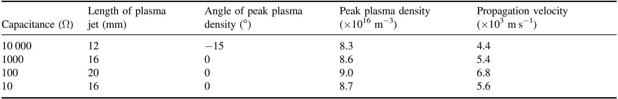
Table 6.Plasma parameters with different capacitances.
Acknowledgments
This work is supported by the Fundamental Research Funds for the Central Universities(No.2019YJS187)and National Natural Science Foundation of China(No.51577011).
 Plasma Science and Technology2021年6期
- Plasma Science and Technology的其它文章
- Diagnostics of a microhollow cathode discharge at atmospheric pressure
- The investigation of OH radicals produced in a DC glow discharge by laser-induced fluorescence spectrometry
- Multiple current peaks and spatial characteristics of atmospheric helium dielectric barrier discharges with repetitive unipolar narrow pulse excitation
- Nonlinearity of initiating and extinguishing boundaries of DBDs with airflows
- Study of double-chamber air arc plasma torch and the application in solid-waste disposal
- Charge transfer in plasma assisted dry reforming of methane using a nanosecond pulsed packed-bed reactor discharge