
Nonlinearity of initiating and extinguishing boundaries of DBDs with airflows
2021-06-21 02:00MiaoTANG唐邈JingfengTANG唐井峰DeshengZHOU周德胜andDarenYU于达仁
Plasma Science and Technology 2021年6期
Miao TANG(唐邈),Jingfeng TANG(唐井峰),Desheng ZHOU(周德胜)and Daren YU(于达仁)
Harbin Institute of Technology,Harbin 150001,People’s Republic of China
Abstract Various applications of volume dielectric barrier discharges(DBDs)with airflows have attracted significant attention such as in the fields of plasma medicine,surface modification,ozone synthesis,etc.In this work,the nonlinearity characteristics of DBDs in initiating and extinguishing boundaries with airflows are experimentally investigated.It is found that the difference between initiating pulse repetition frequencies(PRFs)and extinguishing PRFs is affected by the addition of airflows.A hysteresis region is produced between these two PRFs.A topological rule of Thom’s classification theorem is proposed to investigate the hysteresis phenomenon of discharges with airflows.It is concluded that the discharge state is dependent on the operation route.The discharge state would transit from initiating to extinguishing,or in the opposite direction,while passing along a specific operation route.Based on the topological method,two nonlinear laws of discharge structure transition under the typical operation routes are predicted and verified in the discharge experiments.
Keywords:nonlinearity,topological rules,initiating and extinguishing boundaries,DBDs
1.Introduction
The research and application of discharge with airflows has attracted much attention.In many studies,it has been found that airflow can significantly change the characteristics of the discharge,such as the discharge mode[1–4],discharge intensity[1,5–7],discharge stability[8–10],etc.The working boundary of discharge is the basic range that satisfies the establishment of discharge and is an important condition for initiating and maintaining discharge.The working boundary of discharge includes two phases:initiation and extinction.During these two phases,influence factors should be considered,such as electric field,work environment,airflow condition,etc.
The influence of airflow on discharge working boundary has also received attention,mostly focusing on the study of the breakdown characteristics of discharge[6,7,11–20].The position of discharge breakdown moves along the airflow direction,because the airflow will transport the residual particles of the micro-discharge channels[7,11].When the airflow is introduced,due to the increase in the gas density(N),the reduced electric field(E/N)decreases,so the electric field should be enhanced to ensure that the discharge is sustained[6,12].At the same time,the product of higher number density and an unchanged characteristic electrode gap shifts the breakdown point further to the right on the Paschen curve and the working voltage required for discharge breakdown increases[13].When the air flows over the discharge surface,the discharge arc length and discharge voltage are increased and the discharge is extinguished until the Joule heating energy is out of balance[14].
When airflow exists,in addition to natural convection and radiation to transfer energy,constrained convection with greater energy loss is also added[15,16],making Joule heat unable to balance this dissipated energy.In the above studies,it is found that the space charge,surface charge,Joule heating energy,gas density and other factors that sustain the discharge are affected by the airflow,causing the working boundary to change.What is more noteworthy is that the introduction of airflow causes nonlinear phenomena of the working boundary.The air blowing effect(the deflection effect and blown away effect)and airflow density are two factors that affect the breakdown process.When the airflow increases,the breakdown voltage shows a nonlinear change,which first increases and then decreases[17].During the initiation and maintenance of the discharge,the airflow effect also transforms the discharge mode,so that the discharge current changes non-linearly[21].The existence of these nonlinear phenomena brings more uncertainty to the determination of the working boundary in the airflow environment.
The nonlinear phenomenon is common in dielectric barrier discharge(DBD)plasmas[22].When the driving source changes a little,it may result in spatial or temporal nonlinear phenomena in DBDs.Duan et al[23]investigated the sensitivity of discharge patterns to the applied voltage and showed that some significant changes in the discharge pattern are observed with a small change in applied voltage.Even if the discharge conditions remain the same,in some cases,discharge patterns can rotate[24,25],move[26],collide and scatter[27–29],form a spiral and cause chaos[30],and have some other collective effects[31].In order to recognize the complex nonlinear phenomenon of DBDs,the regularity problems of the nonlinear characteristic are widely discussed through mechanism analysis and experimental research.Boeuf et al[32]investigated and found that the plasma filaments of DBDs can exhibit particle-like behavior.Their results showed that the discharge patterns present some dynamical properties under a certain external condition(pressure,voltage amplitude or gap length).Wang et al[33]found the regularity characteristics of the frequency windows of the chaotic state or period multiplication state by simulating the DBD systems under conditions conducive to chaotic states.Ganter et al[34]experimentally studied the evolution of discharge striations in DBD systems.As shown in their work,the striations appear when the plasma expands over the dielectric layer of the anode and the striations are formed regularly along the anode one by one.It is certain that the nonlinearity of DBDs at atmospheric pressure is universal.At the same time,the study of the nonlinear laws is helpful to understand and explore the internal mechanism of DBDs.
The nonlinear phenomenon of hysteresis at the initiating and extinguishing boundaries of DBD has been found in previous work[35].In this study,topological analysis is used to analyze this nonlinear problem from the perspective of the study of nonlinear dynamical systems.The nonlinear phenomena of discharge working boundary are explained by the geometric topology model based on Thom’s classification theorem.Furthermore,the dependence of the discharge state on the operation route is predicted and verified based on topological laws.
2.Experimental setup
Figure 1 is a schematic diagram of the experimental setup.Two parallel electrodes made of stainless-steel plates(80×30×1.5 mm3)are each covered by one mica plate(150×60×1 mm3).The discharges are excited by a repetitive nanosecond pulse supply with a pulse width of 10 ns and rise time of 4 ns,corresponding to the frequency,which ranged from 0–3.8 kHz.The upper and the lower electrodes are the cathode and anode,respectively.The discharge voltage and discharge current waveforms are recorded by a Tektronix oscilloscope(MSO 5104 10 GHz)through a capacitive divider(bandwidth:200 MHz,divider ratio:2200:1)and a Pearson current probe(Pearson 6585).By replacing the orifice plate to change the total pressure of the airflow after the relief valve,an airflow velocity of 0–0.9 Ma in the discharge area can be achieved.The parallel-plane electrodes are installed at the exit of the nozzle with the airflow direction parallel to the electrode surface.Since the airflow remains in an incompressible state(Mach number<0.3),its velocity can be measured through the Bernoulli equation by using a pitot tube and differential pressure meter(DP3000,YIOU Instruments,China).The pitot tube is fixed near the center of the outlet of the discharge chamber,1 cm away from the parallel-plane electrodes.Discharge photographs are captured by a digital camera(Canon EOS 80D)with an exposure time of 1/1250 s and an ISO of 6400.
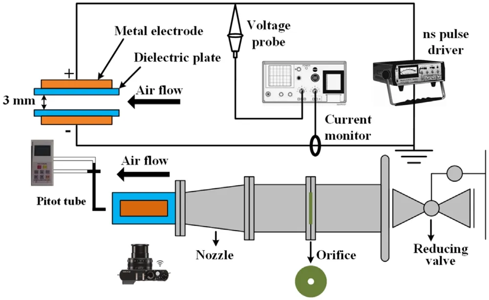
Figure 1.Schematic diagram of the experimental setup.
3.Nonlinearity of the initiating and extinguishing boundaries with airflow
The electrical signals in the process of initiating and extinguishing and the identification of the change of the discharge state have been introduced in the previous work[35].Figure 2 shows the pictures of discharge in the initiating and extinguishing processes at the applied voltage of 18 kV and airflow velocity of 40 m s-1.We increase the pulse repetition frequency(PRF)until one or a few micro-discharge channels are established between the electrodes during the initiating process.With the increase in PRF from 0 Hz,we find the initiation PRF is 1970 Hz.The image of discharge changes from no light to blue-purple filamentary discharge.After the PRF reaches the initial boundary,the discharge image changes.Then,the PRF decreases until the micro-discharge cannot be maintained during the extinguishing process.With the decrease in PRF from 3800 Hz,we find the extinction PRF is 1440 Hz.There are many micro-discharge filaments between the plate electrodes until they disappear gradually,as shown in figure 2.

Figure 2.Pictures of discharge in the initiating and extinguishing processes(applied voltage of 18 kV and airflow velocity of 40 m s-1).
In the process of discharge initiation,collision ionization in the gas gap and secondary electron emission on the cathode form some micro-discharge channels[14,36]between the electrodes.In the process of discharge extinction,the establishment of discharge channels cannot be maintained due to the influence of the power supply parameters and environmental changes.In these two processes,the difference in the evolution process of discharge particles creates the nonlinear phenomena of discharge working boundary.With the introduction of airflow,a large number of active particles are blown away in the gap during discharge,which further impacts the PRFs used for initiating and extinguishing boundaries.The influence of the airflow environment,discharge evolution process and other factors makes the discharge working boundary have a double stable position.The nonlinear characteristics of the discharge state transitions cause uncertainty in the determination of the discharge state.
4.Mathematical rule:a topological property in the initiating and extinguishing boundaries of DBD with airflow
For the discharge system of this experiment,under the input of power supply parameter adjustment and flow rate,a response corresponding to the discharge state(initiating or extinguishing)is generated.This response process is a dynamical system,which necessarily meets the dynamical laws of the dynamical system.For a deterministic system without hysteresis phenomena,it is possible to predict the output of the system in an instant from its input.For a deterministic system with hysteresis phenomena,there is no way to predict the output without knowing the current state of the system and the control routes.In this section,the general rule of state transition is studied in the dynamical system of initiating and extinguishing boundaries[37].
4.1.Topological invariant rules for the stability boundaries of structure transition
The stable boundary of the initiating and extinguishing processes is composed of a series of catastrophe points.According to the stability theory of dynamical systems,catastrophe points are named as singular points,which are critically stable equilibrium points.Singular points are special points at which all the partial derivatives simultaneously vanish;it is this set of singular points that contains the significant behavior of the process.The critical conditions for mode transition correspond to system singular points,which can be expressed with the potential function as[38]:
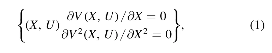
where X is the n-dimension state variable or dependent variable of the system,U is the m-dimension external input and V is the C∞-scalar potential function.Near the singularity,a smooth incremental change in the external input can result in a sudden jump in the state variable.This set of singular points contains the significant behavior of mode transition.
According to Thom’s classification theorem,the potential function for a cusp singularity can be expressed as[39]:
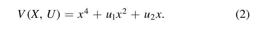
The cusp singularity is illustrated in figure 3(a),where the points on the equilibrium surface are represented by a 3D coordinate space of[u1u2x].By projecting the equilibrium surface,we can get the folded edges of the equilibrium surface,which are called the singularity set.When the operation routes pass through the singularity set,a sudden jump will occur.When the operation routes are far away from this area,the system output changes continuously with the parameters of the operating routes.Therefore,the singularity set can be used to judge whether a sudden jump in the system occurs.
The hysteresis characteristics of the initiating and extinguishing PRFs versus airflow velocity is shown in figure 3(b).It can be seen that the DBD working boundary is a cuspshaped curve,which corresponds to the singularity set for singular systems[40].The topological law implied by the characteristics of singular systems provides the possibility to understand the nonlinearity of initiating and extinguishing boundaries.According to the topological law,the discharge state can be predicted to follow the nonlinear changes of different operating routes.
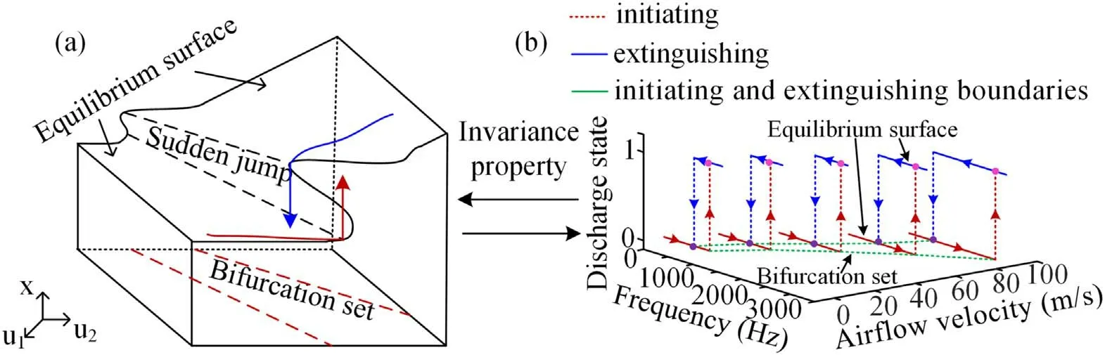
Figure 3.Topological property of structure transition in the initiating and extinguishing boundaries with airflow.(a)Elementary cusp singularity and(b)comparison of hysteresis characteristics at different airflow velocities under applied voltage 18 kV(red lines show the initiating process;blue lines show the extinguishing process;dotted lines show the transition processes).
4.2.Topological interpretation of the hysteresis of the initiating and extinguishing boundaries
As shown in figure 3(a),u1and u2in the topological geometry space of catastrophe represent PRFs and airflow velocities during the topological transformation,respectively.There are two stable equilibrium surfaces in the upper and lower branches of the sudden jump area,corresponding to the two states of initiating and extinguishing,respectively.In fact,the sudden jump area corresponds to the discharge boundaries at which the transition of the discharge state between initiating and extinguishing will occur.These boundaries of the sudden jump area can be used to predict the transition between two stable states(initiating and extinguishing).Adjustment ranges of PRFs and airflow velocities remain outside the sudden jump area and the discharge state will not change.However,the nonlinear problem is inevitable.Due to the different operation routes during the experiment,even if the same experimental conditions are reached,the discharge is in a completely different state.The operation route has a strong dependence on the output.
As shown in figure 3(b),there are initiating and extinguishing stable states and unstable transition states in the discharge process.As the airflow velocities increase,the two stable states still exist and the unstable interval of the transition state becomes larger,which is the same as the evolution characteristic of a cusp-shaped topology described above.In order to more intuitively express the change rule of the jump points of the discharge state,the projection of the jump points on the velocity-frequency axis in figure 3(b)is given,as shown in figure 4.Figure 4 shows the bifurcation set of the discharge boundary at an applied voltage of 18 kV.Here,all the jump points are acquired through ten individual measurements and the corresponding average values and error bands are given.
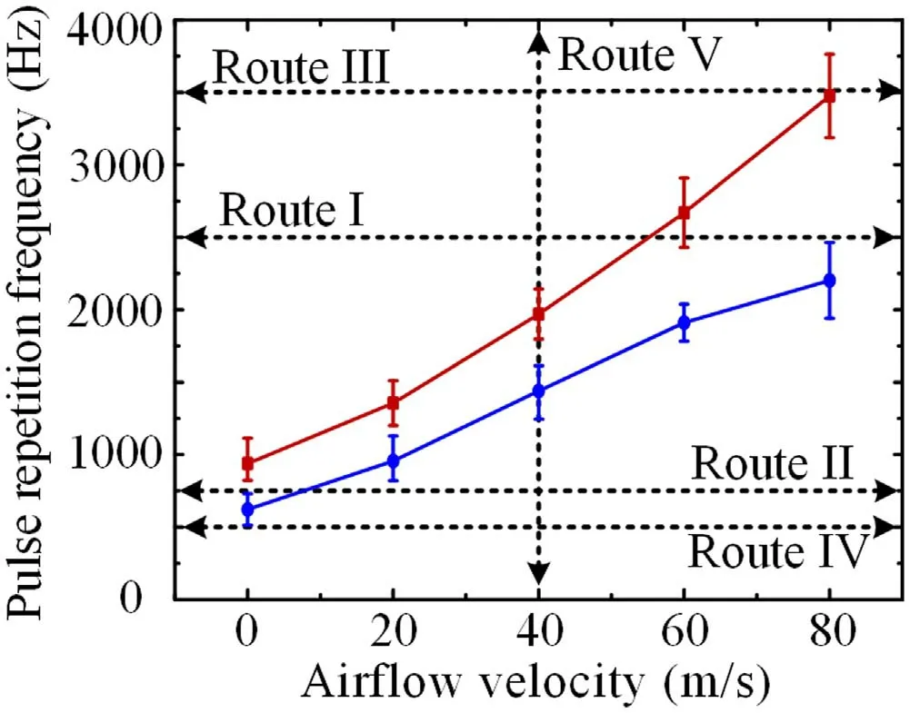
Figure 4.Bifurcation set of the discharge boundary at an applied voltage of 18 kV and the type of operation routes.(red line:initiating boundary;blue line:extinguishing boundary).
4.3.Operation route prediction of discharge states
When the curves of the initiating and extinguishing boundaries and the operation routes are given,the discharge state(initiation or extinction)may be predicted.According to the different operation routes,the initiating-extinguishing state changes have two kinds of nonlinear curves(hysteresis and catastrophe)and a kind of linear curve.If the operation route crosses the initiating(extinguishing)boundary or initiatingextinguishing boundaries,the discharge state changes when the adjustment reaches the vicinity of the catastrophe boundary in a certain direction.The change of initiatingextinguishing state forms a kind of nonlinear curve(hysteresis or catastrophe).If the operation route does not cross the initiating and extinguishing boundaries,there will be no change in the discharge state.The change of initiatingextinguishing state forms a kind of linear curve.
As shown in figure 4,there is a bifurcation set of discharge boundaries and several types of operation routes.When the operation route is Route V,the operation route crosses the initiating and extinguish boundaries.Route V adjusted in both directions will reach the vicinity of the boundary.The discharge state has double jump positions(initiating and extinguishing),leading to the phenomenon of hysteretic.When the operation route is Route I(or Route II),the operation route crosses the initiating(or extinguish)boundaries.Route I is adjusted in both directions and the discharge state transition only occurs in one direction.The discharge state has one jump position(initiating),leading to the phenomenon of catastrophe.When the operation route is Route III(or Route IV),the operation route does not cross the initiating and extinguishing boundaries.Route III(or Route IV)is adjusted in both directions and there will be no change in the initiating(or extinguishing)discharge state.
5.Discharge state varies along different operation routes
Based on the above operation route prediction of discharge states,the initiating and extinguishing discharge states have a strong dependence on the operation route.The following provides the change of discharge state along these operation routes(Route I–V)in the experiment.
As shown in figure 5,the discharge state curve is adjusted along Route I when the voltage amplitude is 18 kV and the PRF is 2500 Hz.When the airflow velocity decreases to 53 m s-1along Route I,the discharge state changes to the initiating state and the discharge image changes as shown by A-B-C(Route I—red line).With the increase in airflow to 60 m s-1,the discharge is still in the initiating state and the discharge image changes as shown by D-E-F(Route I—blue line).As predicted,the discharge state has a jump point along Route I in one direction.The change of initiating-extinguishing state forms a nonlinear curve of catastrophe.
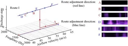
Figure 5.Discharge state versus PRFs and airflow velocity along Route I.(A)65 m s-1,(B)50 m s-1,(C)45 m s-1,(D)40 m s-1,(E)50 m s-1,(F)60 m s-1.(dashed lines indicate the operation route and the red point is the jump point in these processes;solid lines indicate the discharge state on the operation route and the black points are the observation points in these processes).
As shown in figure 6,the discharge state curve is adjusted along Route II when the voltage amplitude is 18 kV and the PRF is 750 Hz.When the airflow velocity increases to 8 m s-1along Route II,the operation route crosses the extinguishing boundary.The discharge state changes to the extinguishing state as predicted and the discharge image changes as shown by A-B-C(Route II—red line).With the decrease in airflow to 0 m s-1(Route II—blue line D-E-F),the discharge is still in the extinguishing state.Only in Route II along the direction of increasing airflow velocity,does the discharge state have the jump position,forming another catastrophe nonlinear curve.
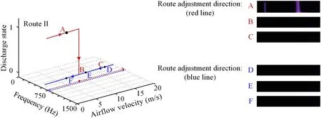
Figure 6.Discharge state versus PRFs and airflow velocity along Route II.(A)5 m s-1,(B)10 m s-1,(C)15 m s-1,(D)15 m s-1,(E)10 m s-1,(F)5 m s-1.(dashed lines indicate the operation route and the red point is the jump point in these processes;solid lines indicate the discharge state on the operation route and the black points are the observation points in these processes).
As shown in figure 7,the discharge state curve is adjusted along Route III when the voltage amplitude is 18 kV and the PRF is 3500 Hz.Route III does not cross the initiating and extinguishing boundaries,irrespective of whether it is adjusted in the direction of increasing or decreasing airflow velocity and so the discharge state remains unchanged.When the airflow velocity decreases to 20 m s-1,the discharge image changes as shown by D-E-F(Route III—red line).When the airflow velocity increases to 60 m s-1,the discharge image changes as shown by A-B-C(Route III—blue line).The same as for Route III,when adjusting along the two directions of Route IV,the discharge state remains the extinguishing state.The discharge state does not jump by adjusting along Route III or IV,forming a linear curve of stable state as predicted.
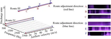
Figure 7.Discharge state versus PRFs and airflow velocity along Route III and Route IV.(A)60 m s-1,(B)40 m s-1,(C)20 m s-1,(D)20 m s-1,(E)40 m s-1,(F)60 m s-1.(dashed lines indicate the operation route;solid lines indicate the discharge state on the operation route and the black points are the observation points in these processes).
The discharge state curve is adjusted along Route V,as shown in figure 2.By two-way adjusting along Route V,the discharge state has double jump points(initiating and extinguishing),forming a hysteretic nonlinear curve as predicted.The prediction of the discharge state along different operation routes based on the topological property in structure transition has been well verified in the experiment.
6.Discussion of the nonlinearity phenomena of the initiating and extinguishing boundaries with airflow
During a typical DBD process,ions,electrons,excited particles and metastable particles,etc,are generated.The lifetimes of the ions and electrons generated in the ionization process are relatively short[41].These particles mainly disappear through recombination and diffusion processes.The excited state particles and metastable particles are generated during the excitation process.Once the excited state particles rise to the metastable state,these metastable particles have a relatively long lifetime(for example,the lifetime of the metastable state of N2and O2is estimated to be ~10-3s or longer)[42,43].When the airflow is introduced between the electrodes,the charged particles are affected by the transport effect of airflow.These particles move along the direction of the incoming airflow or are even blown out the discharge area[2,3,15,44].In this paper,the time between two pulses is about(0–3)×10-4s(PRF of 0–3800 Hz)and the characteristic time of the airflow through the electrodes is(0–8)×10-4s(electrode characteristic length/airflow velocity).These characteristic times are basically of the same order of magnitude as the lifetimes of metastable particles.These metastable species could survive during the pulse interval time and lead to a memory effect.At the same time,the wall charge accumulated on the surface of the dielectric plate is also an important factor affecting the discharge process.Considering the viscous effect of the airflow,the wall charge distribution in the low-speed boundary layer is basically not affected by the airflow.Therefore,the transport effect of airflow and the accompanying memory effect would affect the discharge process and characteristics of the DBD.
In this paper,the influence of the working boundary by the airflow is studied.The transport effect of airflow and the accompanying memory effect also affect the working boundary characteristics.For a certain DBD space,the accumulation degree of particles depends on the particle generation rate and airflow transport rate.When a certain airflow velocity is introduced,the transport effect of the airflow to discharge particles is almost unchanged.The PRF changes the particle generation rate and the pulse interval time.Therefore,the PRF of the excitation pulse has an impact on the initiating and extinguishing boundaries.During the initiating process,the PRF is increased from 0 Hz until there is one or several micro-discharge channels between the electrodes.The density of active particles in each micro-discharge channel area is relatively low.During the extinguishing process,the PRF is decreased from 3800 Hz until there is almost no micro-discharge channel between the electrodes.There are many micro-discharge channels at the beginning of the extinguishing process and the density of the active particles around the micro-discharge channel area is relatively high.As a result,a PRF lower than the initiating PRF is needed to extinguish the discharge.As shown in figure 4,at different airflow velocities,the initiating PRFs are always higher than the extinguishing PRFs.When the airflow velocity is 60 m s-1,the initiating PRF is 2670 Hz,which is 760 Hz higher than the extinguishing PRF.The difference in the number of microdischarge channels and the density of the active particles is the cause of the difference between the initiating and extinguishing boundaries,that is,the hysteresis phenomenon is observed.
With the change in airflow velocity,the influence of the airflow on the discharge results in complex changes.Considering the coupling effect between the charge accumulation on the wall of the dielectric plates and the boundary layer,the process of airflow through the plates is often accompanied by electrostatic force between charged particles and wall charges,collisions and ionization processes between particles and ions,and friction on the surface of the dielectric plate,etc[11,45].These complicated effects show that the influence of airflow on discharge is in accordance with complex laws.As shown in figure 3(b),the hysteresis width generated by the working boundary of discharge changes greatly with the increase of the airflow velocity.When the airflow velocity increases from 0 to 80 m s-1,the hysteresis width is changed from 317 to 1273 Hz.The nonlinear characteristics of the discharge state transitions cause uncertainty in the determination of the discharge state.In this paper,from the perspective of nonlinear dynamical system research,the topology analysis method is used to analyze this nonlinear problem and the discharge state is predicted based on the laws of topology.
7.Conclusion
In this work,the nonlinearity of initiating and extinguishing boundaries of volume DBDs with airflows is investigated.The results show that the region between the initiating and extinguishing PRFs provides a two-valued feature,which leads to a hysteresis phenomenon of discharge boundaries.
(1)To understand the hysteresis phenomenon,a topological rule is proposed based on Thom’s classification theorem.The discharge state is dependent on the operation route and the set of structure transition corresponds to discharge boundaries.When passing along the special direction route through initiating or extinguishing boundaries,the discharge state would be changed(initiating or extinguishing).
(2)According to the topological rules,two nonlinear curves(hysteresis and abrupt)and a steady-state linear curve are predicted.When the operation route crosses the initiating or extinguishing boundaries,the discharge state has jump positions,leading to the phenomenon of catastrophe.However,when the operation route does not cross the initiating and extinguishing boundaries,there would be no change in the discharge state.
(3)The state changes in DBD are verified by the experiments.These general rules in the initiating and extinguishing boundaries may provide a perspective for the understanding of the potential mechanism of DBD with airflows.
Acknowledgments
This work is supported by National Natural Science Foundation of China(Nos.51676053 and 91741204).
 Plasma Science and Technology2021年6期
- Plasma Science and Technology的其它文章
- Diagnostics of a microhollow cathode discharge at atmospheric pressure
- The investigation of OH radicals produced in a DC glow discharge by laser-induced fluorescence spectrometry
- Multiple current peaks and spatial characteristics of atmospheric helium dielectric barrier discharges with repetitive unipolar narrow pulse excitation
- Study of the influence of discharge loop parameters on anode side on generation characteristics of metal plasma jet in a pulsed vacuum discharge
- Study of double-chamber air arc plasma torch and the application in solid-waste disposal
- Charge transfer in plasma assisted dry reforming of methane using a nanosecond pulsed packed-bed reactor discharge