
岩石钻孔爆炸致裂研究
2021-12-03 08:49郭晓钧文鹤鸣
高压物理学报 2021年6期
郭晓钧,文鹤鸣
(1. 南昌航空大学土木建筑学院,江西 南昌 330063;2. 中国科学技术大学中国科学院材料力学行为和设计重点实验室,安徽 合肥 230027)
It is very important for mining and civil construction to predict the morphology distribution of cracks induced by blasting. Hence, many researchers have paid their attention to dynamic fracture behavior of rocks due to drilling and blasting operations[1-3]. A number of experiments and numerical simulations have been conducted to investigate the blasting-induced fractures in the near borehole zone as well as in the far field[4-5]. In order to gain high fidelity in simulating the complex responses of rocks subjected to blasting loading, a realistic constitutive model is required. In the last 20 years, various macro-scale material models have been proposed, from relatively simple ones to more sophisticated, and their capabilities in describing actual nonlinear behavior of material under different loading conditions have been evaluated[6].
During blasting operation, chemical reactions of explosive in borehole occur rapidly, and instantaneously a shock/stress wave applies to borehole wall. Initially, a crushed zone around the borehole is developed by the shock/stress wave. Then, a radial shock/stress wave propagates away from borehole, and its magnitude decreases.Once the radial shock/stress drops below the local dynamic compressive strength, no shear damage occurs. At the same time, a tensile tangential stress with enough strength can be developed behind the radial compressive stress wave, which results in an extension of the existing flaws or a creation of new radial cracks. If there is a nearby free boundary, the incident compressive stress wave changes to a tensile stress wave upon reflection, and reflects back into the rock. In this case, if the dynamic tensile strength of rock is exceeded, spall cracks appear close to the free boundary.
The purpose of this paper is to conduct a numerical study on borehole blasting-induced fractures in rocks.First, a dynamic constitutive model for rocks based on the previous work of concrete[7]is briefly described, and the values of various parameters in the model for granite are estimated. The model is then employed to simulate the borehole blasting-induced fractures in granitic rocks. Comparisons between the numerical results and the experimental observations are made, and a discussion is given.
1 Dynamic Constitutive Model for Rocks
A number of models for concrete-like materials, such as TCK model[8], HJC model[9], RHT model[10], K&C model[11], have been developed. The sophisticated numerical models are increasingly used as they are capable of describing the material behavior under high strain rate loading. However, these models have been found to have some serious flaws, and cannot predict the experimentally observed crack patterns or exhibit improper behavior under certain loading conditions[7,12-15].
In the following, a dynamic constitutive model for rocks is briefly described according to equation of state(EOS) and strength model, based on the previous work on concrete[7].
1.1 EOS
A typical form of EOS is the so-calledp-α relation, which is proved to be capable of representing brittle material’s response behavior at high pressures, and it allows for a reasonably detailed description of the compaction behavior at low pressure ranges as well, as shown schematically in Fig.1.pcrushcorresponds to the pore collapse pressure beyond which plastic compaction occurs, andplockis the pressure when porosity α reaches 1,fttis the tensile strength,ρ0is the initial density, ρs0refers to the density of the initial solid.
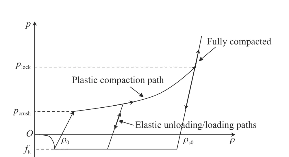
Fig. 1 Schematic diagram of EOS[7]
The EOS for compression (p≥0) is given by

wherepdenotes pressure,K1,K2,K3are constants, and µ¯ is defined by
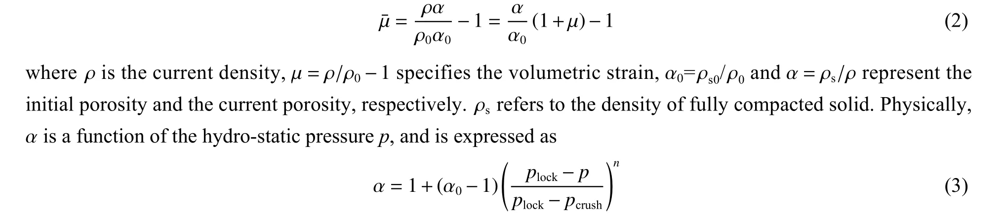
wherenis the compaction exponent.
When material withstands hydro-static tension, the EOS for tension (p<0) is given by
1.2 Strength Model
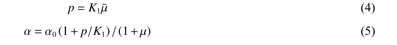
The strength model takes into account various effects, such as pressure hardening, damage softening, third stress invariant (Lode angle) and strain rate. The strength surfaceY, shown schematically in Fig.2, can be written as[7]
Fig. 2 Schematic diagram of the residual strength surface for rock in total stress space

wherepis the hydro-static pressure, parametersBandNare constants,R(θ,e) is a function of the Lode angle θ and the tensile-to-compressive meridian ratioe,fc′is the static uni-axial compressive strength, the compressive strengthfccand the tensile strengthfttare defined by
whereftis the static uni-axial tensile strength.
Dm_tis the compression dynamic increase factor due to strain rate effect only, and can be expressed as[7,16]

whereDtis the tension dynamic increase factor determined by

whereFm,Wx,WyandSare experimental constants, ε˙ is the strain rate, and ε˙0is the reference strain rate, usually taken ε=1.0 s−1.
ηcis the damage function for compression, which can be expressed as

wherelandrare constants[7], λmis the value of shear damage ( λ) when strength reaches its maximum value under compression. η(λ) is defined as

ηtis the damage function for tension which can be written as
2 Numerical Simulations
Granite is selected for investigating the dynamic fractures which result from borehole blast loading.
2.1 Evaluation of Various Parameters in the Model
Table 1 lists the values of the various parameters used in the dynamic constitutive model for granite. As to how to determine the values of the various parameters in the model, more details are presented in [7, 15-17].
Table 1 Values of various parameters for granite[7,15-17]
Fig.3 shows the comparison of the strength surface between Eq.(6) (withB=2.59,N=0.66) and the triaxial test data for granite[17]. It can be seen from Fig.3 that a good agreement is obtained. Similarly, Fig.4 shows the tensile strengths/dynamic increase factor obtained by Eq.(10) and the test results of various rocks at different strain rates[18-23]. It is clear from Fig.4 that a good agreement is achieved.
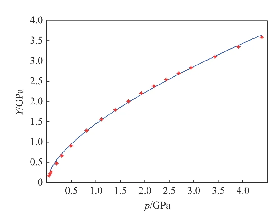
Fig. 3 Comparison of the strength surface between Eq.(6) (with B=2.59, N=0.66) and the triaxial test data for granite[17]
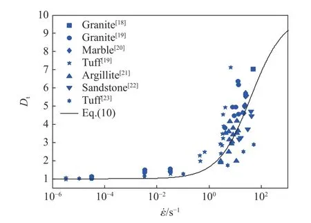
Fig. 4 Tension dynamic increase factor obtained by Eq.(10) and the test results of various rocks at different strain rates[18−23]
2.2 Numerical Results
In the following, numerical simulations are carried out for the response of the granite targets subjected to borehole blasting loading. The dynamic fracture behavior of two kinds of granite samples are studied, namely,cylindrical sample as reported in the literature and square sample as examined in our own laboratory.
2.2.1 Cylindrical Rock Sample
In consideration of the sizes of the cylindrical granite samples prepared for laboratory-scale blasting experiments by Dehghan Banadaki and Mohanty[17](with a diameter of 144 mm, a height of 150 mm and a borehole diameter of 6.45 mm), a circular plane strain model with an outer diameter of 144 mm is made in our simulation, as shown in Fig.5, being a scaled close-up view of the borehole region. Multi-material Euler solver is used for modeling PETN explosive, polyethylene and air. Lagrangian descriptions are used for modeling the copper tube and granite.
The material model and the properties of PETN explosive, polyethylene, air and copper tube used in the simulation are given in Ref.[17]. The values of various parameters in the constitutive model for granite are listed in Table 1.
Fig.6 shows the comparison of the peak pressures between our simulation results of the present model, the numerical results[17], and the experimental results by Dehghan Banadaki and Mohanty[24]. It can be seen from Fig.6 that a good agreement is obtained.
In order to characterize the damping behavior of stress in granite, the peak pressurepin granite is expressed in an exponential form as
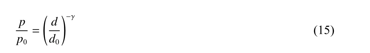
wherep0is the peak pressure on the borehole wall,d0is the initial radius of the borehole,dis the distance from the center point of the borehole, γ is an index. It is evident from Fig.6 that Eq.(15) with γ=1.6 correlates well with the experimental results.

Fig. 5 Close-up view of the borehole region showing the material positions and the meshes
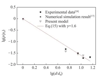
Fig. 6 Relation between the peak pressure and the distance from the borehole wall in granite
Fig.7 shows the comparison between the crack patterns predicted numerically based on the present model and the one observed experimentally in the cylindrical granite sample[17]. It is clear that a relatively good agreement on the crack pattern is obtained. It is also clear that the stress waves produce three distinct crack regions in the cylindrical granite sample: densely populated smaller cracks around the borehole, a few large radial cracks propagating towards the outer boundary, and circumferential cracks close to the sample boundary which are due to the reflected tension stress.
Fig. 7 Comparison of the crack patterns between the numerical prediction and the experiment of the cylindrical granite sample[17]
In order to make an assessment of the contributions of both the compression/shear stress and the tensile stress to the crack patterns, Fig.8 shows the numerically predicted crack pattern which results from the tension stress only. Fom Fig.8 and Fig.7(a), it is apparent that there are virtually few changes in crack patterns, both having the large radial and circumferential cracks caused by the same tensile stress,however, the smaller cracks around the borehole in Fig.8 are much less than those in Fig.7(a). In another word, crack patterns are mainly caused by tensile stress, and smaller cracks around borehole are created largely by compression/shear stress.
Fig. 8 Numerically predicted crack pattern resulting from tension stress only
2.2.2 Square Granite Sample
The laboratory-scale single-hole blasting tests are also carried out in order to validate further the accuracy and the reliability of the present model. Two square granite samples with a side length of 400 mm and a height of 100 mm are employed in the experiments. The borehole diameter is 4 mm and a series of concentric rings is drawn on the top surface of the samples (see Fig.9), so that the damage regions induced by detonation can be assessed visually.
Fig. 9 Square granite sample
Fig. 10 Cross-section of the cylindrical RDX enclosed by an aluminum sheath
A cylindrical RDX explosive enclosed by an aluminum sheath (see Fig.10) is tightly installed in the borehole of the No.1 sample, while an unwrapped RDX explosive is inserted into the borehole of the No.2 sample. The density of the RDX is 1 700 kg/m3, and the material model and properties of the RDX explosive and the aluminum sheath used in the experiments are given in ref.[25]. The values of the various parameters in the constitutive model for granite are listed in Table 1.
Fig.11 and Fig.12 show the comparisons of the crack patterns between the numerical predictions from the present model and the ones observed experimentally in the square granite samples. It can be seen from Fig.11 and Fig.12 that good agreements are obtained. It should be mentioned here that No.1 sample receives less damage due to less RDX explosive used in the test, and that No.2 sample is broken up into four major pieces due to more RDX explosive employed in the experiment. Severe damages and small cracks are induced in the vicinity of the boreholes of both samples, as can be seen clearly from Fig.11(b) and Fig.12(b).
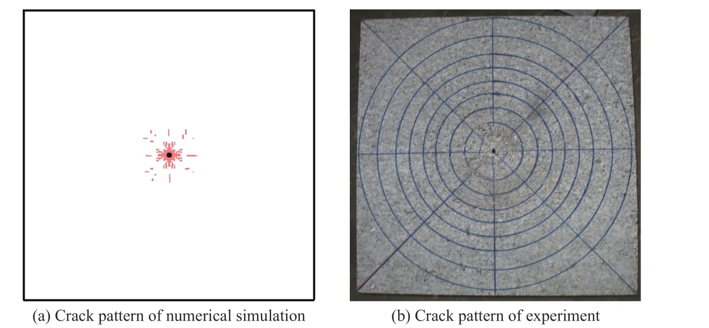
Fig. 11 Comparison of the crack patterns between the numerical prediction and the experiment with the square granite No.1 sample
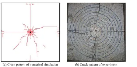
Fig. 12 Comparison of the crack patterns between the numerical prediction and the experiment with the square granite No.2 sample
3 Conclusions
A numerical study on the borehole blasting-induced fractures in rocks is conducted in this paper, using a dynamic constitutive model developed previously for concrete. Two kinds of granite rocks are simulated numerically, one in the cylindrical form and the other in the square form. The numerical results are compared with the corresponding experiments. Main conclusions can be drawn as follows.
(1) The crack patterns predicted numerically from the present model are found to be in good agreement with the experimental observations, both in cylindrical and square granite samples subjected to borehole blasting loading.
(2) The peak pressures predicted numerically based on the present model are found to be in good agreement with the test data.
(3) Crack pattern observed experimentally in the rock sample is mainly caused by the tensile stress, while the smaller cracks in the vicinity of the borehole are created largely by compression/shear stress.
(4) The consistency between the numerical results and the experimental observations demonstrates the accuracy and reliability of the present model. Thus the model can be used in the numerical simulations of the response and the failure of rocks under blasting loading.
猜你喜欢
中国科学院院刊(2023年2期)2023-02-27
剧作家(2023年1期)2023-02-06
——李振声
干旱地区农业研究(2022年3期)2022-06-09
课程教育研究(2021年10期)2021-04-13
黄河之声(2021年19期)2021-02-24
装备制造技术(2020年2期)2020-12-14
书香两岸(2020年3期)2020-06-29
中山大学学报(自然科学版)(中英文)(2020年1期)2020-02-26
中国科学院院刊(2016年8期)2016-03-24
人间(2015年16期)2015-12-30
