
Helium bubble formation and evolution in NiMo-Y2O3 alloy under He ion irradiation
2022-04-12 03:48AwenLiu刘阿文HefeiHuang黄鹤飞JizhaoLiu刘继召ZhenboZhu朱振博andYanLi李燕
Chinese Physics B 2022年4期
Awen Liu(刘阿文) Hefei Huang(黄鹤飞) Jizhao Liu(刘继召)Zhenbo Zhu(朱振博) and Yan Li(李燕)
1School of Physical Science and Technology,Shanghai Tech University,Shanghai 201210,China
2Shanghai Institute of Applied Physics,Chinese Academy of Sciences,Shanghai 201800,China
3School of Nuclear Science and Technology,University of Chinese Academy of Sciences,Beijing 100049,China
Keywords: NiMo-Y2O3 alloy,dose rate,helium bubble evolution,volume fraction
1. Introduction
As one of six candidates for generation-IV fission reactors, molten salt reactors (MSRs) have attracted wide attention in the field of nuclear energy because of their inherent safety,reliability,and high efficiency.[1,2]MSRs were designed to operate at high temperatures and highly corrosive fluoride molten salt is applied as the coolant. The structural materials used in MSRs face service conditions such as high temperature, strong molten salt corrosion, and high neutron irradiation,[3]and these conditions will pose a huge challenge to their performance.[4]Because of their excellent resistance to high-temperature molten salt corrosion, nickelbased alloys have been widely developed to meet the service conditions of MSRs.[5]The Oak Ridge National Laboratory,USA, developed a nickel-based Hastelloy N alloy for applications in MSRs, which was considered to be the first option for structural metallic components in MSR due to its excellent chemical compatibility with fluoride molten salts.[6]However, severe helium embrittlement occurs in the Hastelloy N alloy under high neutron irradiation doses.[7]During operation, the nickel of Hastelloy N alloy is prone to the nuclear transmutation reaction (n,α) with neutrons, and generates helium atoms. These helium atoms aggregate and form helium bubbles because of their low solubility, leading to further helium swelling in the alloy.[8-10]It has been found that helium swelling severely damages the mechanical properties of nickel-based alloys.[11-13]Accordingly,the development of excellent helium embrittlement resistance materials is a critical issue when ensuring both safe and longer cycles in MSRs.
To solve this problem, Huanget al.[14]developed a new nickel-based ODS alloy, with yttrium oxide nanoparticles(Y2O3NP) in dispersion-strengthened phases and NiMo as a matrix. It has been confirmed that the dispersion of Y2O3NPin the alloy enhances its mechanical properties. In addition,the high number density of interfaces in the alloy between the Y2O3NPdispersion-strengthened phases and the NiMo matrix is capable of enhancing the absorption of helium atoms and inhibiting the formation and coarsening of helium bubbles,leading to improved helium embrittlement resistance of the alloy.Furthermore, the irradiation resistance of an alloy is closely related to the evolution of irradiated defects, which is generally believed to be affected by various factors,such as irradiation temperature,irradiation dose,and dose rate.[15-19]Among these factors, few investigations on the irradiation dose rate have been reported.
To evaluate the application potential of this type of alloy in high-temperature MSRs, in this study, helium ion irradiation experiments on the NiMo-Y2O3alloy with three different irradiation doses and varying irradiation dose rates at 750°C were performed. The evolution of helium bubbles,especially the change in the mean size and number density of helium bubbles under different irradiation conditions,is characterized and analyzed using transmission electron microscopy(TEM).In addition, the helium bubble volume fraction of the NiMo-Y2O3alloy is also compared with the currently widely used nickel-based Hastelloy N alloy to further evaluate its potential applications to MSRs.[11]
2. Materials and methods
A new type of NiMo-Y2O3alloy was prepared by powder metallurgy. A mixed powder of 81 wt%Ni, 17 wt%Mo,1 wt% Y2O3and 1 wt% stearic acid, was sintered by spark plasma after milling for 4 h. The detailed process employed here is reported in Ref. [20]. The prepared samples were cut into 10 mm×6.5 mm×1 mm thin slices. Then, mechanical polishing was conducted with silicon carbide papers from grade P400-4000, followed by alumina suspensions, to obtain a smooth surface. Electropolishing was subsequently performed at 36 V and 0°C for 10 s using an electrolyte consisting of 50%H2SO4, 40%C3H8O3, and 10%deionized water,which was used to remove the surface stress induced by mechanical polishing. To characterize the microstructure of the alloy before irradiation,samples were prepared in the form of disks of 3 mm in diameter for TEM observation. These were prepared by mechanical thinning down to 50 µm, followed by twin-jet electropolishing with an alcoholic solution of 5%HClO4. Finally,the samples were cleaned with a mixed solution consisting of 50%alcohol and 50%acetone to obtain the TEM foil specimens.
The as-prepared samples were irradiated with 1 MeV helium ions at doses of 1×10¹⁶ions/cm2, 3×10¹⁶ions/cm2,and 5×10¹⁶ions/cm2at 750°C using a 4 MV Pelletron accelerator located at the Shanghai Institute of Applied Physics,Chinese Academy of Sciences (SINAP-CAS), respectively.The ions beam was raster scanned over the irradiation area at 37.01 Hz horizontally and 17.09 Hz vertically. The irradiation times were selected to be approximately 7800,9600,7200 and 10200 s,and the corresponding irradiation dose rates were approximately 1.28, 3.11, 6.94 and 4.90×10¹²ions/(cm2·s),respectively. The irradiation experimental parameters of samples S0-SRare listed in Table 1. Samples SRis the Hastelloy N alloy which is used for reference with samples S0-S3of NiMo-Y2O3alloy. During the irradiation,the temperatures of the samples did not increase significantly owing to the limited ion beam intensity(<1µA).
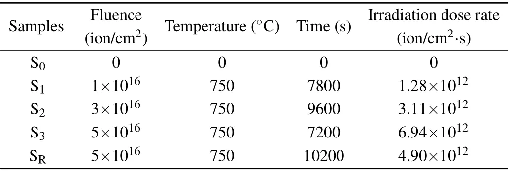
Table 1. Experimental parameters of samples S0-SR.
Figure 1 shows the distribution curves for displacement per atom (DPA) and He concentrations calculated using the simulation software SRIM-2013.[21]The atomic displacement energies recommended by the American Society for Testing and Materials (ASTM) were used with the K-P calculation model (Ni-40 eV, Mo-60 eV),[22]As is shown, the irradiation damage depth was approximately 2 µm, where the peak damage regions of the DPA and He concentration curves were located at the depths of 1650 nm and 1700 nm,respectively.
The cross-sectional TEM samples were prepared using the focused ion beam (FIB) technique on FEI Nanolab 600 equipment, which adopts a gallium ion beam. To avoid irradiation damage caused by gallium ions, in the final stage of cross-sectional sample preparation,a 2 keV gallium ion beam was used to clean the samples at a current of approximately 5 pA.The as-prepared FIB samples were characterized using a Tecnai G2 F20 TEM apparatus with an accelerating voltage of 200 kV. The specific thicknesses of the FIB samples were measured using convergent beam electron diffraction(CBED)technology. The results of TEM observations are presented in Section 3.

Fig.1. Helium concentration and irradiation damage profiles produced by 1 MeV He+ ions with different irradiation doses: (a) DPA and (b)He concentration.
3. Results and discussion
A TEM bright-field micrograph of the unirradiated NiMo-Y2O3alloy is shown in Fig.2. A large number of black spots were dispersed in the alloy,which has been identified as Y2O3.[14]The sizes of Y2O3were in the range of 4-20 nm,and their mean size was 4.93 nm,as calculated by satisfactory results.
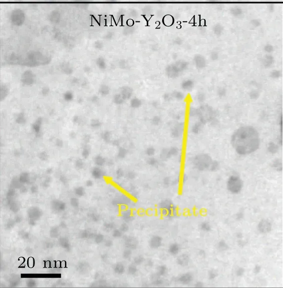
Fig.2. TEM bright-field micrograph of unirradiated sample S0.
Figure 3 shows the TEM images of the NiMo-Y2O3alloy irradiated by 1 MeV He+ions at a dose of 1×10¹⁶ions/cm2(1.28×1012ion/cm2·s)at 750°C.The entire irradiation damage region forms the surface in the vicinity of the peak damage,as shown in Fig.3(a). The white dots were formed in the matrix and grain boundaries of the alloy,and were mainly distributed in the depth range of approximately 1600-2000 nm.Moreover, the distribution of these white dotes was consistent with the He concentration distribution calculated using SRIM. The corresponding images in Figs. 3(c) and 3(d) obtained under the under-focus(c)and over-focus(d)conditions suggest that these white spots are helium bubbles.[17]Figure 3(b)shows an enlarged peak damage region. The helium bubbles were perfectly distributed along the grain boundaries,and relatively fewer helium bubbles were present in the matrix. This may be attributed to the fact that grain boundaries,acting as vacancy sources, could provide sufficient vacancies for helium atoms to form vacancy-helium complexes. These complexes can act as nucleation sites for helium bubbles.[23]Furthermore,the grain boundaries can act as a strong trap for helium atoms and small helium clusters;[24,25]thus, helium atoms are preferentially absorbed by the grain boundaries during diffusion under irradiation,[11,26]leading to more helium bubbles appearing in the grain boundaries.

Fig. 3. (a) Bright-field TEM image of an NiMo-Y2O3 alloy irradiated by 1 MeV He+ ions at a dose of 1×10¹⁶ ions/cm2. (b) Enlarged micrograph of the blue box in(a).The under-focus and over-focus micrographs of the yellow box in(a)are provided in(c)and(d),respectively.
Figures 4(a),4(b),and 4(c)show the TEM images of the NiMo-Y2O3alloy irradiated by 1 MeV He+ions at a dose of 3×10¹⁶ions/cm2(3.11×1012ion/cm2·s).There is a slight deviation between the distributions of helium bubbles in Fig.4(a)and the SRIM prediction,where the damage region of the helium bubbles is located at a depth of approximately 1600-2000 nm. Similar behavior has been observed before.[14]Owing to thermal diffusion and a longer irradiation time in sample S2, the helium atoms are capable of diffusing into the deeper matrix,[27]resulting in the aforementioned deviation.
Figure 4(d) shows the TEM images of the NiMo-Y2O3alloy irradiated by 1 MeV He+ions at a dose of 5×10¹⁶ions/cm2(6.94×1012ion/cm2·s). Similar to sample S2,the distribution of helium ion concentration was located at a depth of approximately 1600-2000 nm. The enlarged micrographs of the yellow box in Fig.4(d)obtained under the underfocus and over-focus conditions are shown in Figs. 4(e) and 4(f).
In this work, a comparison between the NiMo (NP) and Hastelloy N alloys,focusing on helium-induced damage,was conducted to reveal the irradiation resistance of the former.Figure 5 shows the TEM images of the Hastelloy N alloy irradiated by 1 MeV He+ions at a dose of 5×10¹⁶ions/cm2(4.90×1012ion/cm2·s). The damage region of the helium bubbles is located at a depth of approximately 1600-2000 nm.Different from sample S3,there is a slight deviation in the distribution of helium bubbles of SR. The helium atoms diffused deeper into the matrix of NiMo-Y2O3alloy than Hastelloy N alloy.
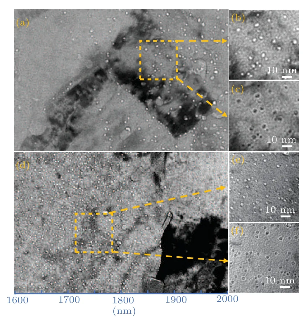
Fig. 4. (a) and (d) Bright-field TEM images of an NiMo-Y2O3 alloy irradiated by 1 MeV He+ ions with doses of 3×10¹⁶ ions/cm2 and 5×10¹⁶ ions/cm2, respectively. [(b), (e)] and [(c), (f)] Micrographs of the yellow boxes under the under-focus and over-focus conditions,respectively.
Based on the TEM observation results, the sizes of helium bubbles in the irradiated samples were measured using the Nano Measurer software. Figure 6(a) shows the distribution of helium bubble sizes of the four irradiated samples(S1,S2,S3and SR)in the peak damage region. It can be found that the helium bubble sizes were mainly concentrated within the range of 2-4 nm.The thicknesses of samples S1,S2,S3and SRmeasured by the CBED method are about 36.0 nm, 36.0 nm,35.8 nm and 34.5 nm,respectively.
A detailed analysis of the collected TEM images, focusing on the number density and mean size of helium bubbles,is presented in Fig. 6(b). These counts include not only bubbles observed in the matrix but also those distributed along the grain boundaries at a depth of 1600-1900 nm. Figure 8 shows increasing number densities of observed helium bubbles of 0.85±0.06×10²³m-3, 1.05±0.08×10²³m-3, and 2.19±0.10×10²³m-3with increasing helium ion dose rate.In general, helium bubbles tend to grow with increasing ion fluence. It is noted that, although helium ion fluence continuously increases, the mean helium bubble size first increases from 3.3±0.5 to 3.9±1.1 nm,then decreases to 2.9±0.5 nm.It is reasonable to conclude that their unique evolution is due to the ion irradiation dose rate.
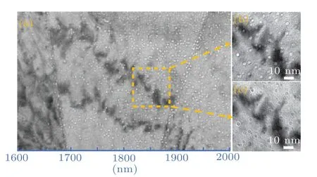
Fig. 5. (a) Bright-field TEM image of a Hastelloy N alloy irradiated by 1 MeV He+ ions at a dose of 5×10¹⁶ ions/cm2. Under-focus and over-focus micrographs for the yellow box are shown in (b) and (c),respectively.
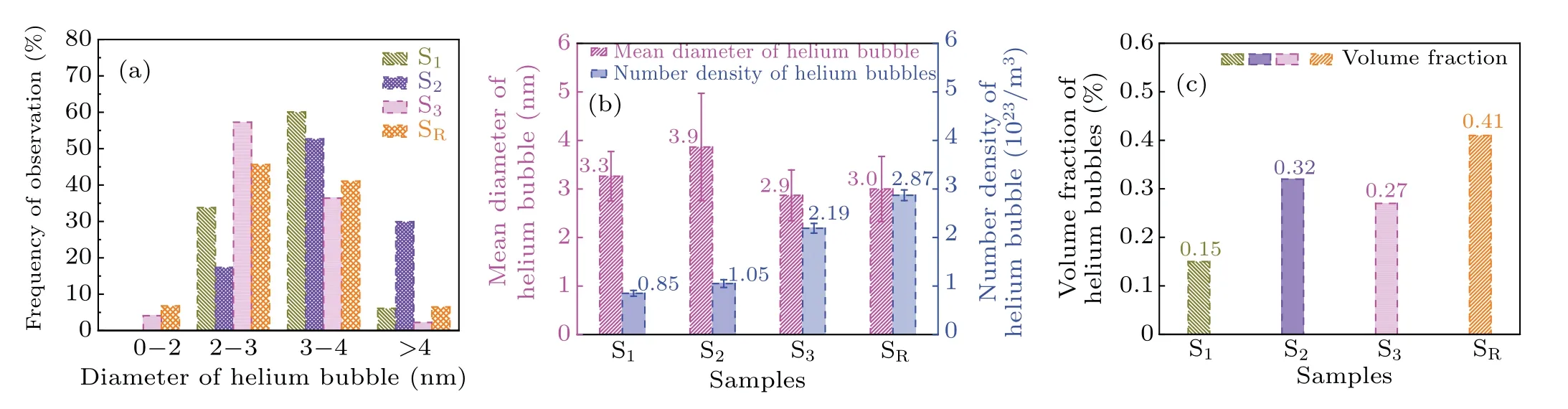
Fig.6. (a)Size distribution of helium bubbles in the irradiated samples(S1,S2,S3 and SR)at a depth of 1600-1900 nm from the surface. (b)Mean diameter and number density of bubbles. (c)Volume fraction of helium bubbles.
High-energy particle irradiation results in the formation of vacancies and interstitial atoms, which are generated as a result of displacement cascade.During the irradiation process,most interstitial atoms and vacancies are annihilated when they encounter each other. The remaining vacancies and helium atoms combine to form helium-vacancy clusters, which can act as nucleation sites for helium bubbles.[23]Helium bubbles nucleate and coarsen by continuously absorbing helium atoms and vacancies.[28]It should be noted that the dose rate can affect the evolution of point defects and further the evolution of helium bubbles. In the case of a low ion irradiation dose rate,the vacancies introduced by energetic ions have sufficient time to encounter interstitial atoms,thus leaving few surviving vacancies combined with helium atoms to form helium bubbles.Variations in the helium bubble size and number density of the four alloy samples shown in Fig.6(b)can be explained as follows. Compared with S1, as shown in Fig. 6(b), both the mean size and number density of helium bubbles in sample S2increased. Owing to the increased irradiation dose rate in sample S2,more helium-induced vacancies were generated and then remained after annihilation. Owing to the increasing supply of helium-induced vacancies and helium atoms, more vacancy-helium complexes were generated and helium bubbles continuously nucleated and coarsened.[23]In addition,the increase in irradiation time also stimulated the nucleation and coarsening of helium bubbles.[29]Therefore,the mean size and number density of the helium bubbles increased in sample S2.In addition,it is noticed that the mean size of helium bubbles decreased in S3when the dose rate of helium ion irradiation was further increased. Compared with sample S2a large number of helium-induced vacancies were generated in sample S3while the irradiation dose rate reached a high level,and there were still many vacancies that had not yet been annihilated during irradiation. Many vacancy-helium complexes then generated and dispersed the nucleation sites of the helium bubbles,leading to an insufficient supply of helium atoms for coarsening of helium bubbles. Therefore,sample S3exhibited a smaller mean helium bubble size,though with an increase in number density,compared to sample S2.
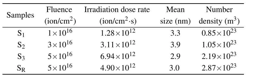
Table 2.Mean size and number density of helium bubbles under different irradiation conditions.
The characterization of helium bubbles observed in Hastelloy N irradiated by He+ions at a dose of 5×10¹⁶ions/cm2at 750°C (denoted as sample SR) is shown in Fig. 6(b). The mean size and number density of the helium bubbles in sample SRwere 3.0±0.7 nm and 2.87±0.11×10²³/m3, respectively. It is noted that the number density of helium bubbles generated in sample S3is higher than that of sample SR,while the mean size of helium bubbles observed in sample S3is almost identical to that of sample SR,which suggests that the dispersed phase in the new alloy inhibited the coarsening of helium bubbles in the alloy, to a certain extent.It is well understood that the interfaces between the dispersion phases and nickel matrix,and also grain boundaries,can absorb helium atoms.[11]Most helium atoms diffuse to these sinks, leaving a small number of helium atoms to form bubbles. On the other hand,because interstitials in metals generally diffuse faster than vacancies,[16]these interfaces preferentially absorb interstitial atoms,leaving behind a large number density of mobile vacancies,further increasing the number of nucleation sites of the helium bubbles. This leads to the formation of a large number of small invisible He bubbles in S3.Thus,the statistical number density of the helium bubbles observed in S3is less than that of SR.
After high-temperature helium ion irradiation, the presence of helium bubbles causes helium swelling of the alloy.The severity of helium swelling is related to the volume fraction of helium bubbles in the alloy,[11]which can be calculated using the following formula:[30]
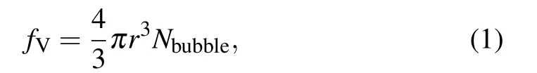
whereris the mean radius of helium bubbles, andNbubbleis the number density of helium bubbles. The volume fractions of helium bubbles at the damage peak regions in the three samples(S1,S2,and S3)were calculated to be 0.15%,0.32%,and 0.27%,respectively. As shown in Fig.6(c),it is clear that the volume fraction of helium bubbles initially increased and then decreased with increasing irradiation dose rate and ion fluence.Note that the largest volume fraction of helium bubbles among the three investigated sample was still smaller than that of the reference sample SR(0.41%). It may be reasonably concluded that the NiMo-Y2O3alloy exhibits better helium swelling resistance than the Hastelloy N alloy.
4. Conclusion
In this study, the evolution of helium bubbles in three NiMo-Y2O3alloy samples S1-3under different irradiation dose rates was characterized using TEM. The related mechanisms were studied and compared with a Hastelloy N alloy sample. The main conclusions are listed as follows:
(1)The statistical number density of helium bubbles generated in the new type of dispersion-strengthened NiMo-Y2O3alloy samples continuously increased, while the mean size of the helium bubbles first increased and then decreased with increasing irradiation dose rate. This is a possible consequence of the different irradiation dose rates employed, which affect the nucleation and coarsening of helium bubbles.
(2) Because the doped Y2O3NPdispersed the nucleation sites of the helium bubbles,a smaller volume fraction(0.27%)of helium bubbles appeared in the NiMo-Y2O3alloy compared with the Hastelloy N alloy (0.41%). Induce that the NiMo-Y2O3alloy exhibits better helium swelling resistance than the standard Hastelloy N alloy that is currently indicated for use in MSRs.
Acknowledgements
This work was supported by the National Natural Science Foundation of China (Grant Nos. 12022515, 11975304, and 91126012) and the Youth Innovation Promotion Association,CAS(Grant No.202063).
猜你喜欢
中华诗词(2022年5期)2022-12-31
文苑(2020年11期)2021-01-04
青年歌声(2020年4期)2020-04-24
启迪与智慧·下旬刊(2019年2期)2019-09-10
小天使·一年级语数英综合(2019年5期)2019-06-27
儿童故事画报·智力大王(2017年2期)2017-06-05
儿童故事画报·智力大王(2015年10期)2016-01-27
儿童故事画报·智力大王(2015年7期)2016-01-27
Defence Technology(2012年1期)2012-03-09
娃娃画报(2009年10期)2009-12-07

- Chinese Physics B的其它文章
- Quantum walk search algorithm for multi-objective searching with iteration auto-controlling on hypercube
- Protecting geometric quantum discord via partially collapsing measurements of two qubits in multiple bosonic reservoirs
- Manipulating vortices in F =2 Bose-Einstein condensates through magnetic field and spin-orbit coupling
- Beating standard quantum limit via two-axis magnetic susceptibility measurement
- Neural-mechanism-driven image block encryption algorithm incorporating a hyperchaotic system and cloud model
- Anti-function solution of uniaxial anisotropic Stoner-Wohlfarth model