
Module-level design and characterization of thermoelectric power generator
2022-04-12 03:48KangZhu朱康ShengqiangBai柏胜强HeeSeokKimandWeishuLiu刘玮书
Chinese Physics B 2022年4期
Kang Zhu(朱康) Shengqiang Bai(柏胜强) Hee Seok Kim and Weishu Liu(刘玮书)
1Department of Materials Science and Engineering,Southern University of Science and Technology,Shenzhen 518055,China
2Shenzhen Engineering Research Center for Novel Electronic Information Materials and Devices,Southern University of Science and Technology,Shenzhen 518055,China
3The State Key Laboratory of High-Performance Ceramics and Superfine Microstructure,Shanghai Institute of Ceramics,Chinese Academy of Sciences,Shanghai 200050,China
4Center of Materials Science and Optoelectronics Engineering,University of Chinese Academy of Sciences,Beijing 100049,China
5Mechanical Engineering,School of Engineering&Technology,University of Washington Tacoma,Tacoma,WA 98402,USA
Keywords: thermoelectric,module-level design,characterization
1. Introduction
Thermoelectric power generation, based on the Seebeck effect,is an established technology that initially served as direct heat to electricity conversion for deep space missions.[1]It also holds promise for the waste heat recovery applications into electricity,which is used to increase fuel economy[2]and provides a battery-free power supply for IoT sensors.[3]The past years have witnessed significant advances in thermoelectric materials, benefiting from both theoretical interpretation and various new syntheses techniques. The thermoelectric figure-of-merit,ZT,defined by A.F.Ioffe,[4]serves as a critical parameter to guide the material-level design,
It provides a simple picture to connect the energy conversion efficiency of thermoelectric devices to the measurable transport parameters of thermoelectric materials,including electrical conductivity, Seebeck coefficient, and thermal conductivity.The measuring methodology of these thermoelectric transport parameters has been well established.[5]The combination of laser flash method for thermal diffusivity and the differential scanning calorimeter for the specific heat provides accurate measurement of thermal conductivity, which corrects the thermal conductivity of the PbTe system.[6]The progress of the measurement technique corrects theZTvalues and allows to consider the accuracy of the prevalent theoretical interpretation. In the latest international round-robin tests of n-type half-Heusler materials(300-800 K),the uncertainty ofZTwas determined to be about +16.7%.[7]Thermoelectric materials development has been focused on improvingZT. However,the gap between laboratory research and commercial applications must be narrowed by reliable materials properties. For example, recently, Peiet al.proposed a new minimum lattice thermal conductivity by considering the correction of the heat capacity model, which could eliminate the contradiction between the experiment observation and Cahill’s values.[8]Weiet al.have made an elegant commentary on the reliable measurement of the thermoelectric transport parameters.[9]
While material property measurement has been standardized,the module-level characterization has many challenges in measuring methods and acceptable standard facilities. Many practical issues have rarely been addressed yet,including different device architectures, heat loss calibration, and interfacial resistances. The device assembling or system integration also adds extra challenges to obtain the reliable systemlevel performance. The interface between electrode and thermoelectric elements requires a low interfacial resistivity and strong mechanical bonding to survive under large thermal stresses.[10]The interfacial thermal resistances between the thermoelectric device and the heat source/sink also increase the complex to obtain accurate module-level performance.[11]A “standard module” is needed regardless of the materials,temperature range, and applications so the power generation capacity and conversion efficiency can be evaluated under the same standard.
Here, in this perspective, we would shine some light on the module-level design and characterization in a timely manner. Firstly, we inspect the materials selection, thermal management,and structural design of thermoelectric modules(TEMs). Secondly,we summarize the general methods available for the assessment of the output performance,with a particular attention on the heat flux measurement. Finally, we present the challenges for reliable measurement systems and future directions of thermoelectric device characterization and call for establishing a standard test procedure.
2. Module-level design
2.1. Material selection
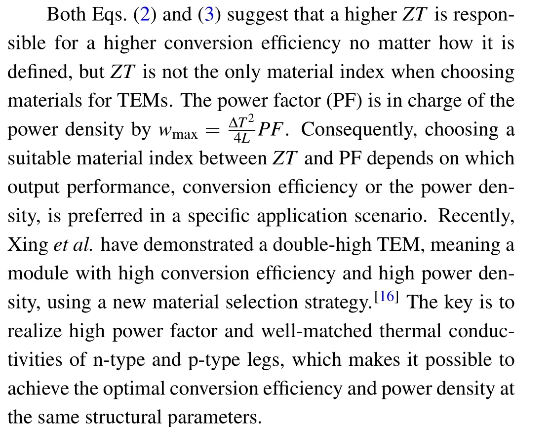
The thermoelectric figure-of-merit(ZT)provides a direction to explore newly developed thermoelectric materials from an efficiency point of view.However,in real cases,the thermoelectric transport properties and hence theZTvalue are heavily temperature dependent,resulting in a proper working temperature range and hence a limitation for most thermoelectric materials. Furthermore,the temperature-dependentZTvalues also embarrass the calculation of efficiency by using Eq. (2)derived from a constant property assumption.An accurate way is to numerically solve the one-dimensional heat transfer for the temperature gradient across the legs and obtain the output electricity and input heat.[12]However,the numerical calculation is time-consuming and not convenient to use.[13]Alternatively,an averageZTover a temperature range,together with Eq. (2), is adopted to roughly estimate the efficiency and explain the superiority of new materials by many material scientists.
Kimet al.proposed a more rigorous cumulative temperature dependence model and redefined the relationship between the efficiency and the materials performance scale engineering(ZT)engwithin a wide temperature range in the following way:[14]
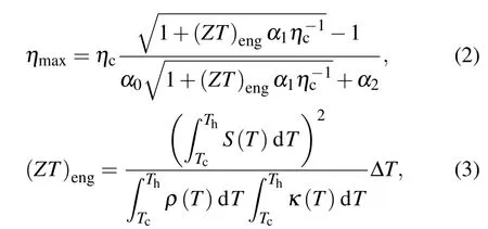
whereηcis the Carnot efficiency andαi(i=0,1,2)are nondimensional parameters representing practical contribution of Peltier heat,Thomson heat,and Joule heat,depending on a degree of temperature dependence of properties. (ZT)engshows a linear correlation with the efficiency regardless of materials systems and operating temperature ranges,[15]which would provide module-level engineers a reliable performance evaluation of materials across a large temperature difference.
2.2. Thermal management
TEMs are primarily characterized under fixed temperatures,provided by the controllable heater and cooler,as illustrated in Fig.1(a). However,the constant temperature boundary condition is impractical in real applications because of the finite heat transfer rates.The real thermal boundary conditions are characterized by the heat transfer coefficients at both the hot and cold sides(Fig.1(b)). Landmannet al.[17]carried out a comparison between thermal boundary conditions of fixed temperatures and constant heat transfer coefficients for TEMs based on half-Heusler materials, where the heat source and heat sink temperatures were set as 605°C and 30°C,respectively,with the hot side heat transfer coefficient being assumed to be 4 kW·m2·K-1,and the cold side heat transfer coefficient to be 1.5 kW·m-2·K-1. It was found that the temperature difference in a real thermal boundary case was 345°C rather than 575°C in the idea case, which resulted in 50% reduction of the output power. The temperature slip of a TEM under a real thermal condition was recently analyzed by Zhuet al.[18]They derived an explicit formula to directly evaluate the effective temperature difference across the module under certain heat transfer conditions. Besides the operating performance, the cost of the heat exchanging system would be another critical factor in the external thermal environmental design. A comparative study was performed on the output performance as well as the cost of a TEG system,under three different types of cooling methods,i.e.,air cooling,water cooling and heat pipe cooling.[19]The power consumptions of the auxiliary equipments such as fans and pumps were taken into account when evaluating the net energy efficiency. As a result of the economic analysis, the air cooling method is found to have the lowest initial investment while the most inferior output performance and the highest specific heat exchanger cost in a unit of$·W-1·K-1. The water cooling method could lead to a better output performance but accompanied with higher auxiliary consumption. The heat pipe produces the best output performance and consumes the lowest specific heat exchanger cost despite the highest initial investment.

Fig. 1. (A) Ideal thermal condition for a TE device; (B) practical thermal condition for a TE device; (C) variations of optimal leg length and maximum power density versus the combined heat transfer coefficient for a Bi2Te3 unicouple (Th =250 °C, Tc =25 °C, ZT =1.1);[39] (D) the thermal resistance match condition for maximum output power.[39]
2.3. Structural design
Structural design usually involves the architecture selection and the thermal resistance match under a given external thermal environment. Classic TEMs are typically assembled in theπ-shape architecture. For TEG applications under large temperature gradients,the concerns on the thermomechanical stresses and output performance motivate the efforts to exploit new architectures.[20,21]Various structures beyond the conventionalπ-shape have been investigated,including the linear design,[22-24]angled structure,[25]cylindrical-shaped[26]and tapered structures.[27]Recently,Heet al.[28]have made an excellent review relative to module architectures.
Once the architecture is determined, the critical task would be choosing the proper internal structural parameters to match the heat flux boundary in Subsection 2.2. The fillfactorf,defined as the area ratio of thermoelectric legs to the substrate, the thermoelectric leg lengthLand theAp/Anratio are three important geometric parameters,[29]among whichAp/Ancould be set to 1 for fabrication convenience and thermomechanical safety if the properties of the p and n type materials are well matched,[30]so it will not be discussed here.Under ideal conditions with fixed hot source and cold sink temperatures, a higherfand a lowerLare beneficial to give both lower internal electrical and thermal resistances,allowing higher heat flux and output power.However,it is more complicated in a real circumstance. As the leg length is too small or the fill factor too high, the effective temperature-drop across the module will be very limited due to the minor occupancy of the internal thermal resistance in the whole thermal circuit.Suarez[31]demonstrated that only about 5% of the available temperature difference between the core of a human body and the ambient could fall into the thermoelectric device due to large contact resistance at the interfaces. Mayer and Ram[32]suggested a longer leg length of thin-film TEMs to increase the power density under heat sink-limited conditions. On the other hand,if the internal thermal resistance occupies the central part of the thermal circuit(meaning the legs are long and thin), a large portion of the available temperature difference will fall into the device. However,the heat flux would be significantly reduced due to the excessive total thermal resistance,resulting in small output power density.
The trade-off between the allowing heat flux and the effective temperature drop is a critical topic to achieve high output power performance,which is referred to as thermal resistance match in the literature.[33-38]Baranowskiet al.[39]defined an effective thermal conductivity (κeff) in such a way that the relationship between the heat flux(qh)and the effective temperature drop (ΔTTE) within the leg could be treated in a simple manner as
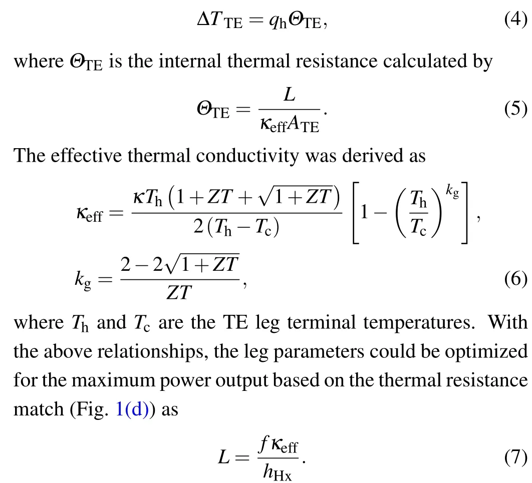
The optimal leg length,as well as the maximum output power,is depicted in Fig.1(c)as a function of the heat transfer coefficienthHxwith specified temperature conditions and material properties. Although Baranowski’s work offers a way to guide the thermal resistance match, it is noted that the leg terminal temperatures are unknown priori in real applications, as discussed in the former section. It is better to use the heat source and sink temperatures,which are directly available,instead of those of the leg terminals in the guiding formula.Zhuet al.[18]proposed a new guideline for thermal resistance match as
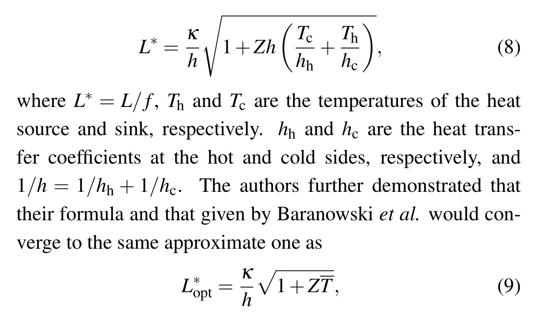
under relatively limited available temperature differences.Overall, the above two formulae lead to similar module parameters,but that in Eq.(8)is more convenient to use since it circumvents the unknown leg terminal temperatures.
3. Module level characterization
The output power and conversion efficiency are the most important scales at the module-level characterization. It is quite mature to measure the output power precisely. Once a temperature difference is created across a module,the electric output power generation is measured by configuring a voltage as a function of electric current(I). There are two methods to measure theI-Vcurve and the output power (P) along with the current flow: (1) adjusting a tunable electric load resistance (RL),[40]and (2) controlling a current flow using a current source meter.[41]Both settings are valid for power output measurement, however, the current control method by a current source is more popular and more accessible to implement than the variable external load resistance method. In addition,the effects of connectors and lead wires on the terminal voltage could be well eliminated by using the 4-probe measuring method.
Under fixed temperature boundary conditions,the device efficiency(η)is obtained according to the definition formula,i.e.,η=P/Qh, wherePis the output electrical power andQhis the input heat flux transferred to a thermoelectric device from the heat source. However, the measurement of the heat flux is very challenging as compared with the output power measurement.In contrast to the electrical current,the heat flux is more difficult to be regulated in a specified unique direction and could be dissipated through various pathways. In large temperature difference circumstances, the accurate measurement of incoming heat flux is even more challenging because of the intensive parasitic losses by radiative, convective and conductive heat losses.[42]Here,we will summarize available strategies and methods for measuring the heat flux and minimizing the measuring errors.
3.1. Hot side heat flux based measurement
The heat flux at the hot side is usually measured according to Fourier’s law of thermal conduction.[41]Technically, a reference block with known dimensions and thermal conductivity is inserted between the heat source and TE device to obtain the temperature gradient within the block,as shown in Fig.2(a). The dimensions and material of the reference block should be carefully chosen to possess a reasonable thermal conductance range as compared with the TE materials. Thermometers are usually inserted in blind holes machined in the reference material to measure the temperature profile. Theoretically, the temperature gradient within the block can be obtained using just one pair of thermometers. While in case of low heat flux or a slight temperature gradient, it is beneficial to arrange multiple(4 or 5)thermometers into the block,to minimize errors caused by position uncertainties and individual derivations among thermometers.[43]The temperature profile could also be measured using an infrared camera.[44]Furthermore,the thermoelectric method,which is based on the Seebeck effect,was also reported to measure the heat flux.[40]

Fig.2. Measurement configuration based on one-dimensional heat flow. (a)A commercial system(PEM-2)by ULVAC,[54] where 7 thermocouples are used to measure heat flux on hot and cold sides and the boundary temperatures (Th and Tc). (b) The measurement system by AIST.[55] Cu blocks are used for heat source and heat sink materials and heat flux on cold side is measured from 6 resistance temperature detectors(RTDs). The boundary hot and cold side temperatures are measured by AlN thin plates. (c)The measurement set-up is enclosed by the heated radiation shield that is suspended and its temperature(T∞)is controlled with similar to the hot side temperature(Th). The cold side temperature is maintained by the combination of the water circulation and a thermoelectric cooler. The input heat energy is measured by the electrical heater power (PH) and no reference material is needed to measure the heat flux.[17,56] (d) A symmetric vertical structured measurement set-up. A thin AlN heater plate is sandwiched by two identical thermoelectric devices and the assembly is compressed by an air cylinder unit. On both sides of thermoelectric devices,Cu spreaders are inserted to detect temperatures,Th and Tc. This system also measures the heat flow by the electric power input.[49]
The heat loss calibration for the hot side heat flux measurement is worthy of being given more attention. In a contact measurement system, the cables of sensors act as thermal bridges to disperse heat out of the device,introducing errors to the heat flux,particularly for devices of mini or micro sizes.[45]When the measurement is carried out in atmospheric environment, air convection emerges. A deviation of 15% in conversion efficiency was reported between a measurement in vacuum and that in atmosphere,for the same module under a temperature difference of 25 K.Under high temperature conditions, thermal radiation is recognized as an important error source,and some means have to be taken to minimize its influence on the measurement of heat flux. A radiation shield was adopted to envelop the high-temperature section from the cold side and surroundings,and the shield should be well thermally insulated.[46]
The use of a reference heat flow meter to measure the heat flux can cause deviations due to the systematic errors of temperature readings across the reference block and uncertainty of the thermal conductivity of the reference material. Alternatively,an electric heater could serve as the heat source,whose electric power, regarded as the input heat flux of the module, can be easily measured by electrical methods.[47]Kraemeret al.[48]utilized a radiation shield heated close to the heater temperature to minimize the parasitic heat losses from the heater component through radiation,as shown in Fig.2(c).In Ref. [49], a symmetric configuration (Fig. 2(d)) was applied, with a single heater sandwiched between two test devices and heat sink components, so that the heat provided by the electric heater is equally transferred to both devices. Apart from the heat losses caused by the ambient,the Joule heating and thermal conduction along the lead wires and electrodes of the electric heater should also be carefully considered.[50]
For solar thermoelectric generators, the incoming heat flux at the hot side was assessed by measuring the incident solar radiation power. In Kraemeret al.’s work[11,51]on thermal(and optical) concentrating solar thermoelectric generators, a solar simulator with an AM 1.5G filter was adopted to impose radiation to the absorber on the hot side of a TEG.The device was enclosed within a vacuum environment to reduce convection heat loss. The incident heat flux was measured by a calibrated power meter as well as a calibrated solar cell. The conversion efficiency was calculated based on the incident heat flux and the output power, which consequently included the heat losses caused by the glass, the absorber layer, and parasitic electrical and thermal losses of the whole system.
3.2. Cold side heat flux based measurement
Due to the inevitable heat loss under high temperatures,a precise measurement of the hot side heat flux is challenging. Alternatively, considering the relationship among heat fluxes and power output,i.e.,Qh=P+Qc,the cold side heat flux could be measured instead,and the conversion efficiency can be rewritten asη=P/(P+Qc).[41,52,53]Compared to the measurement of the hot side heat flux, the cold side heat flux measurement has the advantage of fewer heat losses caused by conduction, convection, and radiation due to the comparable temperature to the surroundings. Figures 2(a) and 2(c)depict the output power and efficiency measurement systems,in which a thermoelectric device is placed between a heat sink unit and a heater part made of nickel(Fig.2(a),a commercial system by ULVAC[54]) or copper (Fig. 2(b) by AIST[55]and Fig.2(c)by lab-made system[17,56]).The heat flux is measured at the cold side using copper as a reference block. If the cold side is cooled by a water loop with controlled mass flow rate,the cold side heat flux could also be obtained by measuring the temperature difference of water into and out of the cooling module. This method is particularly suitable for large-scale TE systems for industrial applications with a large heat flow rate.[57]Although the heat transfer between the cold side and the surroundings is significantly reduced due to limited temperature differences, the cold side heat flux could be affected by the thermal radiation from the hot side of the testing system. Hence it is essential to keep the cold side insulated from the hot side.
3.3. Harman method and impedance spectroscopy approach
The direct testing configuration for thermoelectric performance provides a practical operating environment. However,it demands longer measurement time for a steady-state condition,and complicated calibrations to account for the parasitic heat losses. Indirect measurement techniques for the devicelevel performance are available based on Harman method and impedance spectroscopy,providing a quick estimation of the module-level performance. Harman method[58]enables a moduleZTmeasurement under adiabatic conditions. The total voltage is measured as a sum of the Ohmic voltage(Vohm)and Seebeck voltage (VSeebeck) when a DC current is applied to a device,in which the thermal power pumped by Peltier effect is equal and opposite to the heat transported by thermal conduction under adiabatic conditions. The moduleZTis obtained byZT=VSeebeck/VOhm,whereVOhmis instantaneous by the Ohmic nature andVSeebeckis lagging due to the response of temperature,as shown in Fig.3(a). One critical point when using this method is to extractVOhmfrom the total voltage.Chaveset al.[59]realized high resolution(±0.008)moduleZTcharacterization from the ohmic resistance measured by using AC current flow at optimized frequency. In this method,an appropriate operation frequency is crucial as it should be high enough to avoid Peltier induced voltages but low enough to prevent any reactance in the circuit which could affect the measurement. Figure 3(b)shows a measurement setup for directly measuringZTvalue of a TE couple,in which the parasitic heat loss is minimized by the heated radiation shield and the vacuum environment. To eliminate errors caused by temperature non-uniformities within the experimental setup,a differential form of the Harman method was proposed,in which the deviceZTwas calculated byZT=dVtot/dVOhm-1. The slope ofVtotversusVOhmwas obtained by performing transient voltage measurement with several different direct currents. Figure 3(c) depicts a comparison between the directly measuredZTvalues and those calculated from measured intrinsic thermoelectric leg properties at different temperatures,which gains much confidence in this method.[60]
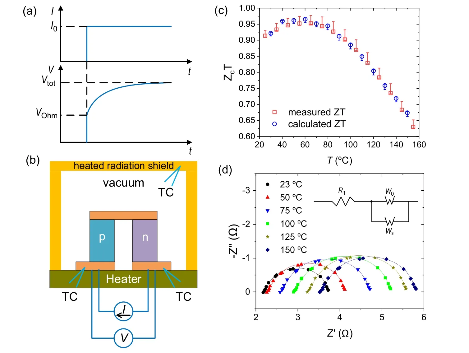
Fig.3.(a)The voltage change as a function of time based on the transient Harman method,where VOhm is the voltage changes by the resistive nature and Vtot is the total voltage. (b)A measurement setup based on the Harman method measurement.[60] (c)Comparison between directly measured ZT and calculated ZT at different temperatures. (d)Impedance spectra of the Bi2Te3-based thermoelectric device as a function of temperature for an oscillation voltage of 10 mV up to 150 °C.[61]
Another approach based on an impedance spectrum measured deviceZTunder ambient conditions. Yooet al.[61]reported rapid measurements of the deviceZTand device properties simultaneously at elevated temperature conditions. Figure 3(d) shows the Nyquist impedance spectra and its equivalent circuit of a Bi2Te3based thermoelectric device in the range of 23°C-150°C with an oscillation voltage of 10 mV under open-circuit voltage conditions in the range of 103Hz to 10-3Hz. In the equivalent circuit,WsandWoare the short and open Warburg elements describing the diffusion at the transmissive and reflexive boundaries,respectively,from which the deviceZTcan be calculated from the Ohmic and Warburg resistance measurements. These techniques characterize a device at a specific temperature that is uniform through the device rather than under a finite temperature gradient.
4. Challenges for optimal design and reliable characterization
In real applications of thermoelectric power generation,the service environment is more complicated than that of laboratory testing. Usually,the heat flow and temperature distribution are not stable,making TE devices’actual output properties diverge from the designed values. Moreover, the coupled unexpected mechanical and electrical changes will dramatically influence the reliability of the TE devices. Therefore, optimizing the TEM’s design and accurately matching the real service conditions are the key issue for maximizing output power and service life of TE devices.
4.1. Changes in the service environment
The laboratory testing environments of TE devices, including the temperature distribution, vacuum, and mechanical and electrical loads, are stable and controllable. However, during the real service, the environments are flexible and unexpectable. For measurement, it is pretty difficult to obtain the relationships between the output properties and environments.[62]For example,when the heat flow is unstable,the temperature distribution changes. The maximum power cannot be obtained if the external load is not modified correspondingly. Actually, to solve this problem, the maximum power point tracking (MPPT) technique will be used in the case of unstable heat flow in real applications.[63-65]For evaluating the TEG system, the most challenging part is to measure thermoelectric energy conversion efficiency because it is challenging to acquire the accurate heat flow. For a closed energy system, the total energy efficiency can be calculated by the output power and input energy,such as RTG.However,it is almost impossible for an open energy system to measure the natural input energy,such as the waste heat of steel factories,solar thermal energy, environment heat, etc. In practice, the cold side heat flow (Qc) was used to calculate the efficiency because its measurement was relatively more accessible than that of the hot side heat flow(Qh).
4.2. Degradations in the internal properties
In the real service environment, the degradations due to the thermal cycles,[66]oxidation,[67]humidity, salt mist, and many others need to be considered. Most TE materials are metal-based semiconductors (except oxide compounds) and sensitive to oxygen, especially at high service temperatures.To prolong the service life of TE devices in real applications,vacuum or hermetic package under inert gas is introduced to isolate them from the outside environment. Mechanical stress is another challenge for TE devices. For most of the TE materials are brittle,such as Bi2Te3and skutterudite,thermal and mechanical vibration or shock results into extra stress, which will cause structural degradation often leading to mechanical failure. Furthermore, the degradation may emerge at the TE materials surface,interface and even inside. For example,oxidation and sublimation appear at the surface, and diffusion and fracture take place at the interface.In system-level design,spring or other buffer structure was used to reduce the stress.However,the evaluation of the degradation of TE devices and the failure mechanism are still not clear,which impede the industrial application of TE power generation.
4.3. Disturbance and loss control in measurements
Because of the unstable service environment,the systemlevel measurement cannot be operated at steady-state. How to control the disturbance of transient response is the key issue to improve the measurement accuracy. Multi-point measurement and minimize response time were used in common.For example, the average temperature from multi-point thermal couples on the same level is more reliable than singlepoint value. Multi-channel data collection of temperatures and voltages with high frequency can reduce the error from the time-delay. Meanwhile, the loss control is also important for system-level measurement. Thermal and electrical losses are caused by external thermal dissipations such as conducting thermal bridges, heat radiations, and internal factors including interfacial resistances.[68]External heat loss calibration is necessary in system-level measurement, especially for hightemperature measurement. The electrical and thermal contact resistances should be estimated to get a fundamental knowledge of the interfacial resistances and their influences within a TEM.[69-78]Furthermore, actions need to be taken to reduce interfacial resistances. For example, the application of comppresive pressure or thermal conductive adhesive can effectively reduce the thermal resistance.
5. Outlook
Thermoelectric power generation has great potential with the increasing concern of the carbon neutral. The development of thermoelectric materials has outpaced module and system development. Recent efforts on improving the quality of materials properties and reliability are essential steps towards commercial applications. Although TEG systems are different from each other,the common features in system designs need to be standardized. For example,an internationally recognized standard module and test procedures need to be developed so various thermoelectric materials made in similar dimensions and basic designs can be compared for power generation capability.[79]At the module level,comprehensive standard for models and simulations should be made to include material properties,electrical and thermal interfaces,hot side/cold side heat exchangers,insulation/packaging materials and degradation and life predictions.
Acknowledgement
The work is supported by Shenzhen DRC project(Grant No.[2018]1433).

- Chinese Physics B的其它文章
- Quantum walk search algorithm for multi-objective searching with iteration auto-controlling on hypercube
- Protecting geometric quantum discord via partially collapsing measurements of two qubits in multiple bosonic reservoirs
- Manipulating vortices in F =2 Bose-Einstein condensates through magnetic field and spin-orbit coupling
- Beating standard quantum limit via two-axis magnetic susceptibility measurement
- Neural-mechanism-driven image block encryption algorithm incorporating a hyperchaotic system and cloud model
- Anti-function solution of uniaxial anisotropic Stoner-Wohlfarth model