
Rotational manipulation of massive particles in a 2D acoustofluidic chamber constituted by multiple nonlinear vibration sources
2022-04-12 03:44QiangTang汤强PengzhanLiu刘鹏展andShuaiTang唐帅
Chinese Physics B 2022年4期
关键词:刘鹏
Qiang Tang(汤强) Pengzhan Liu(刘鹏展) and Shuai Tang(唐帅)
1Jiangsu Provincal Engineering Research Center for Biomedical Materials and Advanced Medical Devices,Faculty of Mechanical and Material Engineering,Huaiyin Institute of Technology,Huaian 223003,China
2State Key Laboratory of Mechanics and Control of Mechanical Structures,Nanjing University of Aeronautics and Astronautics,Nanjing 210016,China
3Jiangsu Key Laboratory of Advanced Manufacturing Technology,Faculty of Mechanical and Material Engineering,Huaiyin Institute of Technology,Huaian 223003,China
Keywords: acoustic streaming,acoustofluidics,ultrasonic vibration,rotational manipulation
1. Introduction
Contactless, non-invasive and label-free manipulation of micro-/nano-scale particles and biological samples on integrated microfluidic platforms (lab-on-a-chip devices) is urgently needed due to the ever-increasing demands on the basic modes of manipulation,[1-3]such as rotation,[4]capture,[5]separation,[6]and agglomeration,[7]which exhibit fascinating applications in biochemical reactions,[8]total analysis of biological organisms,[9]the movement mechanism of micromotors,[10]point-of-care diagnosis,[11]and at-home surveillance of chronic health problems.[12]Different kinds of microfluidic manipulation methods have been extensively investigated in laboratories all over the world. The focal point of micro and nano manipulation technology is to achieve sufficient driving forces which are available to overcome viscous resistance caused by the surrounding microfluidic media or adhesion effect on hydrophilic/hydrophobic fluid-solid interfaces, especially for transformable biological membranes.[13,14]Moreover,there are crucial problems in the existing microfluidic platforms,particularly the difficulties associated with the lab-on-a-chip interconnection to other auxiliary instruments and in the non-invasive and accurate manipulation procedure for living biological samples.[15,16]Currently,an overwhelming majority of microfluidic platforms in worldwide laboratories still require either the assistance of pressuredriven pumps or powerful physical(optical/electric/magnetic)fields, which inevitably leads to a succession of problems that cannot be ignored, such as accidental loss of valuable biological samples and irreversible damage to fragile cell membranes and organelles.[17]Conventional active manipulation strategies for massive particles or biological samples include electric/dielectric,[18]magnetic/diamagnetic,[19]optical,[20]thermal,[21]and acoustic fields,[22]which have the advantages of sufficient driving forces and relatively high manipulation precision. In comparison, existing passive manipulation techniques involve particle filtration,[23]inertial movement,[24]and hydraulic driving,[25]which have the merits of simple equipment requirements and relatively highthroughput detection.
Among the aforementioned manipulation methods,acoustofluidics-assisted manipulation of micro-/nano-scale particles and biological samples has undergone rapid development and gained widespread attention in recent decades.[26,27]In comparison with other manipulation methods, the acoustofluidic field (including acoustic radiation force and acoustic streaming) has already been demonstrated to have the inherent merits of low power consumption, low physiological harm (biocompatibility), contactless, non-invasive and label-free manipulation procedures, non-selective to photoelectromagnetic parameters, and personalized structure customization,[28-30]making it a fantastic choice for extensive applications in a wide range of biomedical/engineering applications. When the acoustic characteristics of the manipulated particles/biological samples differ from the surrounding microfluidic medium, the interaction between the ultrasonic field and the immersed or suspended objects can generate an acoustic radiation force,[31]while an acoustic streaming field commonly originates from the spatial variation of Reynolds stress caused by the sound energy dissipation in viscous media.[32-34]The differences in and applications of these two acoustic effects have been elaborated in a series of references.[35-37]
In recent years, to obtain sophisticated distributions of acoustic radiation forces and acoustic streaming fields, immense numbers of concrete research studies of acoustofluidic fields have been carried out for applications in particle patterning,tissue/organ engineering,and other physico-chemical and biomedical reactions.[29,30,38,39]Considering that the spatial variations in sound intensity and Reynolds stress in the Navier-Stokes equations are the results of time averaging of the sound field distribution, the acoustic radiation force and acoustic streaming field are significantly influenced by the input frequency, oscillation amplitude, and initial phase differences of multiple vibration sources, the acoustofluidic characteristics of different media, and the shape and distribution of fluid-solid interfaces.[40]In general, there are two main types of acoustic streaming:[41,42]one is boundary-layerdriven streaming, which originates from the sound energy attenuation and dissipation occurring in the acoustic viscous boundary layer and can be categorized as inner streaming(i.e.,Schlichting streaming) and outer streaming (i.e., Rayleigh streaming); the other is bulk-wave-driven acoustic streaming(i.e.,Eckart streaming),which is a time-independent net flow along the acoustic propagation path formed by the absorption of sound energy inside the fluidic medium.
In this paper,by referring to the structural design schemes of shaped surfaces on the acoustofluidic fields in lab-on-achip devices proposed by Leiet al.,[43]Courtneyet al.,[44]and Karlsen and Bruus,[45]a novel method to generate diverse rotational acoustic streaming patterns in an ultrasonic chamber only through normal vibration of nonlinear vibration sources is proposed,in which the thickness of the fluidic medium can be ignored in comparison with other dimensions.Therefore,in our simulation work,only a two-dimensional(2D)acoustofluidic model needs to be considered in spite of the fact that it belongs to the bulk-wave-driven acoustic streaming category.By changing the number of vibration sources with different initial phases and adding fixed obstacles,a variety of acoustic streaming vortices can be implemented. The simulated results of the acoustofluidic field and particle trajectory demonstrate that the rotational acoustic streaming field can not only accumulate micro-scale particles in the low-flow area,but can also drive massive particles to rotate clockwise or counterclockwise together with the circumferential vortices. More simulation results of the acoustofluidic fields and particle trajectory patterns at different frequencies are listed in the supplementary material. The spatial variation of vibration source distribution has a direct influence on the distribution of the sound field,while the introduction of obstacles can cause reflection,scattering and diffraction on the propagation path of acoustic waves,eventually leading to different modes of acoustofluidic field.[46]However, since no periodic structures, such as phononic crystal plates,are introduced in this paper,there are no manifested band-pass and band-stop frequency points in the calculation process. Therefore,even if there are fixed obstacles, the distribution of the acoustofluidic field in the ultrasonic chamber is continuously influenced by the change in frequency.
By artificially introducing nonlinear vibration sources of different shapes and sizes in microchannels or lab-onchips and adjusting the excitation conditions of each vibration source(including the setting of amplitude,frequency and initial phase, etc.), more sophisticated patterns of acoustofluidic fields can be implemented from the perspective of structural design. This is available to enable one to overcome the existing problems of monotonous sound fields caused by the commercial piezoelectric ceramic plates or interdigital transducers (IDTs). It also enables the realization of multifunctional controllable manipulation of micro-/nano-scale particles and biological samples, such as cells, viruses and exosomes, where manipulated objects can be dragged along streamlines at specific locations and captured at the stagnation points of acoustofluidic fields.[47-49]Also, diversified acoustic streaming vortices that are generated by adding circular obstacles of different sizes can potentially be used in the research fields of microfluidic mixing of laminar flow under low-Reynolds number,the concentration gradient of chemical reagents, lysis of cellular tissues, enhancement of DNA hybridization,synthesis of organic polymer materials,rotational actuation of micro robot or biological samples, and improvement of heat or mass transfer.[50-53]
2. Theory and method
2.1. The perturbation theory
The perturbation theory and fundamental governing equations of the acoustofluidic field generated by acoustically oscillating sources in a 2D microfluidic chamber have been proposed by other research groups.[54,55]The fluid medium needs to be considered as homogeneous and isotropic. Therefore,the continuity and momentum equations of a Newtonian fluid in differential forms can be expressed as
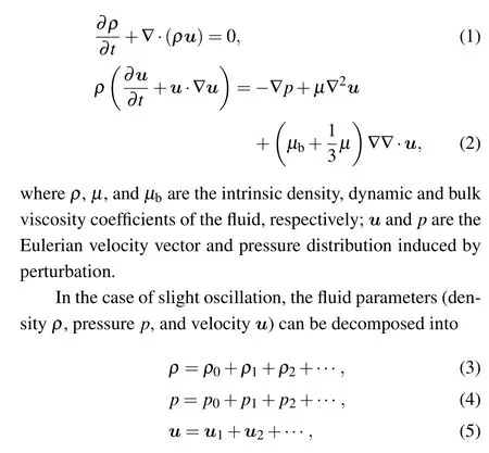
where the subscript characters 0, 1, and 2 represent the static(unperturbed),first-order(oscillating),and second-order(steady streaming) components, respectively. By substituting Eqs. (3)-(5) into Eqs. (1) and (2), the first-order sound field can be written as


2.2. The simulation method
The computational process of the acoustofluidic field consists of three simulation steps using the commercial finite element analysis software COMSOL Multiphysics.[40,46]
In the first step, combining Eqs. (6) and (7) with appropriate acoustic boundary conditions, the first-order sound pressure and velocity field generated by multiple nonlinear vibration sources with different initial phases can be calculated by the ‘Thermoviscous Acoustics, Frequency Domain’ module. The initial settings and boundary conditions of the sound fields are as follows: the oscillation amplitudes, frequencies and initial phases of different vibration sources are set manually;the remaining acoustic boundaries are set to be isothermal and non-slip.
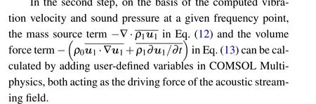
In the last step, the time-independent acoustic streaming field can be solved by the fluidic dynamics module ‘Laminar Flow’using Eqs.(12)and(13).The inertial forceρ0(u2·∇)u2is usually negligible compared with the mass source term and the volume force term in a flow field with a small Reynolds number and is neglected in our simulation.[56,57]All of the flow boundaries are defined as non-slip. To ensure the convergence of flow field calculation,weak contributions of mass source and acoustic streaming pressure are also indispensable.
To calculate the movement trajectory of micro-scale particles in the 2D microfluidic chamber under the combined influence of an acoustic radiation forceFrad(acoustophoretic force)and Stokesian drag forceFdrag(drag force induced by acoustic streaming),the‘Particle Tracing for Fluid’module needs to be taken into consideration.[40,46]
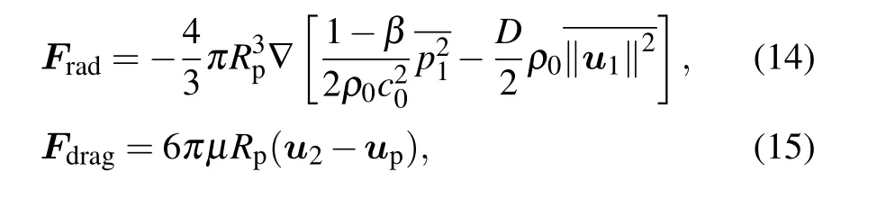
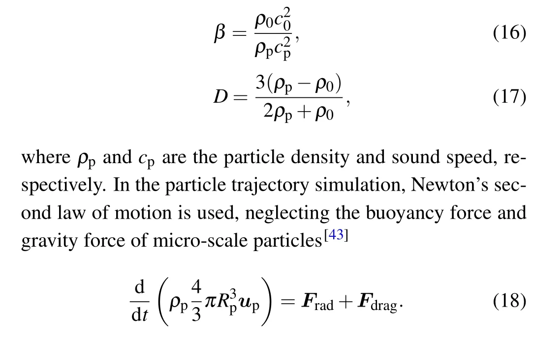
whereRpandupare the radius and velocity of simulated particles,respectively. The parametersβandDare expressed as
3. Results and discussion
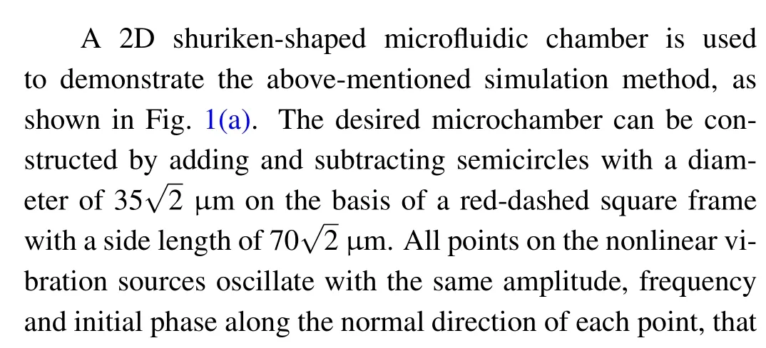

Table 1. Model parameters in the simulation.
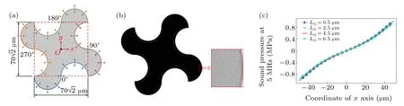
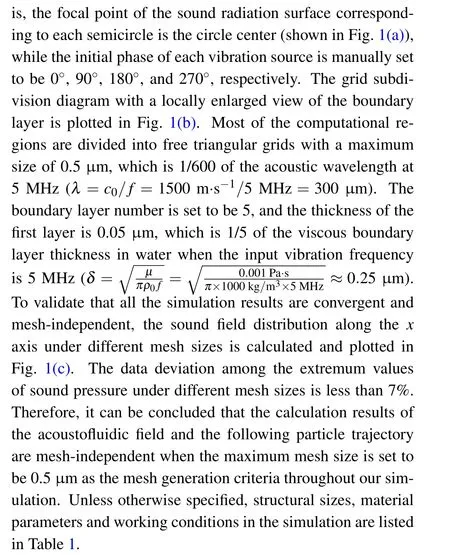
Fig. 1. The 2D shuriken-shaped model for the acoustofluidic field simulation excited by four nonlinear vibration sources. (a) The computational model. (b)The meshed model. (c)Simulated sound pressure along the x axis under different mesh scales.
3.1. Model validation
The sound field and the acoustic streaming distribution in the 2D shuriken-shaped microfluidic chamber generated by nonlinear vibration sources are simulated to validate the proposed model and plotted in Figs. 2(a) and 2(b), respectively.All of the vibration sources have the same input frequency of 5 MHz and normal amplitude of 1 nm, while the initial phase distribution increases along the counterclockwise direction from 0°to 270°(shown in Fig. 1(a)). The color bar in Fig. 2(a) denotes the sound pressure magnitude. Figure 2(b)shows the simulated acoustic streaming field induced by the ultrasonic field, and the color bar represents the magnitude of the acoustic streaming velocity‖u2‖. The plotted white streamlines with arrows are used in Fig. 2(b) to visualize the flow direction of the acoustic streaming field. In addition to four small vortices near the vibration sources, the shurikenshaped microfluidic chamber contains one main circumferential vortex. The rotational direction of the main acoustic streaming vortex is consistent with the increasing direction of the initial phases of the nonlinear vibration sources.[40]To ensure the calculation accuracy of the particle trajectory in Fig. 2(c), the acoustic-streaming-induced drag force and the acoustic radiation force are both considered in the simulation process of 1-µm-diameter particle (polystyrene bead)movement at 5 MHz, while the simulated particle trajectory with comet tails is qualitatively consistent with the streamline of the acoustic streaming field(shown in Fig.2(b)). The above simulation results of the distribution of the acoustofluidic field and the motion trajectory of micro-scale particles can be referred to the existing literature,[34,40,41,44]in which particle aggregation in the center of the ultrasonic chamber or microfluidic mixing along the circumferential direction can be realized under the excitation modulation of multiple ringshaped vibration sources. The simulated acoustofluidic field together with the particle motion trajectory demonstrates that the 2D microchamber actuated by multiple nonlinear vibration sources with different initial phases can potentially be used for microfluidic mixing and rotational manipulation of massive particles or biological samples. Also, the rotational acoustic streaming vortex can be used for controllable rotary driving of silver nanowires or living nematodes.[56,58]To further study the distribution of the acoustic streaming field,a polar coordinate system is established with the chamber center as the original point,and the magnitude of the acoustic streaming velocity is plotted in Fig.2(d)at different polar radii. To be consistent with the initial phase distribution of the vibration sources,the 0°polar angle is manually set to be vertically downward for the convenience of the following research. Corresponding to the existence of four vibration sources on the spatial arrangement,the magnitude curves of the acoustic streaming velocity at different polar radii are all arranged in a four-petal-like distribution. Also, it is found that the closer to the vibration sources,the larger the deviation is between the maximum and minimum velocity magnitudes on a circle of the same polar radius, which can be used to characterize the distortion degree of acoustic streaming vortices or the deformation level of streamlines in Fig. 2(b). By plotting red-dashed auxiliary lines in Fig. 2(d), it is measured that the maximum and minimum velocity magnitudes approximately appear at the polar angles ofθmax=14°~28°+n×90°andθmin=68°+n×90°(wherenequals 0,1,2,and 3),respectively.

Fig. 2. The acoustofluidic field and particle trajectory excited by four nonlinear vibration sources with the same frequency (5 MHz) and amplitude(1 nm). (a)The pattern of the sound pressure field. (b)The pattern of the acoustic streaming field. (c)The pattern of micro-scale particle trajectory at a given time(10 s). (d)Curves of acoustic streaming velocity magnitudes at different polar radii.
3.2. Acoustofluidic fields excited by multiple vibration sources
The acoustofluidic field and particle trajectory at a given time(t=10 s)generated by multiple vibration sources(from five to ten)with different initial phases are simulated,and the simulation results are shown in Fig. 3, while the input frequency points and the normal oscillation amplitudes of all vibration sources are kept constant (5 MHz and 1 nm, respectively). The radii of the circumscribed circles corresponding to the dotted polygons in Fig. 3(a) are all set to be 70 µm.All the sound pressure patterns in Fig.3(a)are approximately anti-symmetric with respect to initial phases of 0°and 180°.Similar to the case with four vibration sources,all of the acoustic streaming fields generated by multiple nonlinear vibration sources(from five to ten)with different initial phases contain one main circumferential vortex inside the microfluidic chamber. The rotational direction of each main circumferential vortex is consistent with the increasing direction of the initial phases,and the regions with larger acoustic streaming velocity magnitude appear around the concave side of each nonlinear vibration source,as shown in Fig.3(b). The simulated particle trajectories of the 1-µm-diameter particle (polystyrene bead)att=10 s in Fig. 3(c) are qualitatively consistent with the white streamlines shown in Fig. 3(b), and it is worth noting that micro-scale particles can be arranged into the corresponding polygonal patterns in the microfluidic chamber under circumstances involving five to seven vibration sources, which can be utilized for patterned arrangement of massive particles.However, starting from eight vibration sources, micro-scale particles that have agglomerated in the microchamber center can no longer be arranged in obvious petal-like distributions.
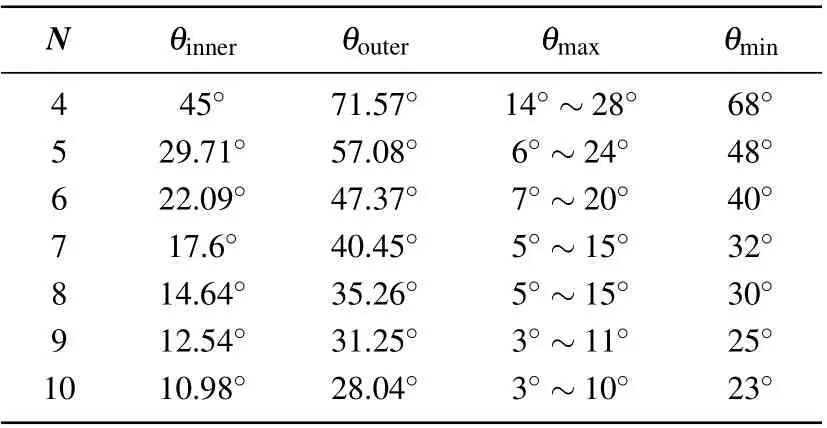
Table 2. Different types of polar angles.
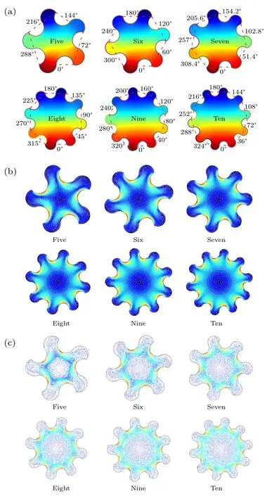
Fig. 3. The acoustofluidic field and particle trajectory excited by multiple nonlinear vibration sources with the same frequency(5 MHz)and amplitude(1 nm). (a) The pattern of the sound pressure field. (b) The pattern of the acoustic streaming field. (c)The pattern of the micro-scale particle trajectory at a given time(10 s).
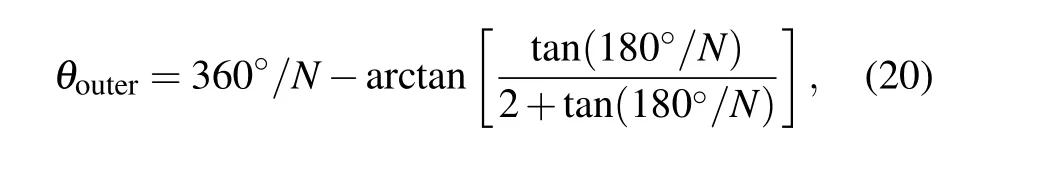
To quantitatively describe the above-mentioned phenomenon, the velocity magnitudes of the acoustic streaming field along polar circles at different radii are analyzed with different vibration source numbers and plotted in Fig. 4(a).Corresponding to the existence of multiple vibration sources on the spatial arrangement, the magnitude curves of acoustic streaming velocity at different polar radii are all arranged in petal-like distributions, and the petal number is consistent with the number of vibration sources. Similar to Fig. 2(d),with the increase in the polar radius, the variation between the maximum and minimum velocity magnitudes on a circle of the same polar radius becomes larger,which means that the distortion degree of the acoustic streaming field also increases.By plotting red-dashed auxiliary lines, the polar angle values corresponding to the maximum and minimum velocity magnitudes which first appear in the 1st quadrant are obtained and are shown in Fig.4(a).Also,the polar angles(θinnerandθouter)of the innermost point of the concave side and the outermost point of the convex side of the vibration sources which first appear in the 1st quadrant can be calculated as follows:
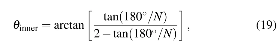
whereNis the number of nonlinear vibration sources. To investigate the relationship among these different types of polar angles,θinner,θouter,θmax, andθminunder circumstances involving four to ten vibration sources are recorded in Table 2,respectively.
Fig.4. Acoustic streaming velocity magnitudes under circumstances involving different vibration sources. (a)Curves of acoustic streaming velocity magnitudes at different polar radii. (b)The averaged acoustic streaming velocity magnitude versus the radius of the polar circle. (c)The averaged angular velocity magnitude versus the number of vibration sources.
Intuitively speaking, on the same polar circle, the maximum velocity is supposed to appear near the concave side of the nonlinear vibration source that is near the center of the microfluidic chamber,while the minimum velocity should appear around the vibration source’s convex side far away from the chamber center. In other words,the polar angle of the innermost point of the concave sideθinneris supposed to correspond to the polar angle of the outer maximum velocity magnitudeθmax, while the polar angle of the outermost point of the convex sideθoutershould correspond to the polar angle of the minimum velocity magnitudeθmin. It can be found from Table 2 that the above-mentioned induction is correct from the perspective of the tendency in data change,except that the difference betweenθinnerandθmaxis about 35% in the four vibration sources. This is because the maximum velocity does not occur exactly at the polar angle of the innermost point of the concave side,especially for the four vibration sources with larger radiation surfaces, where the deviation betweenθinnerandθmaxis larger.
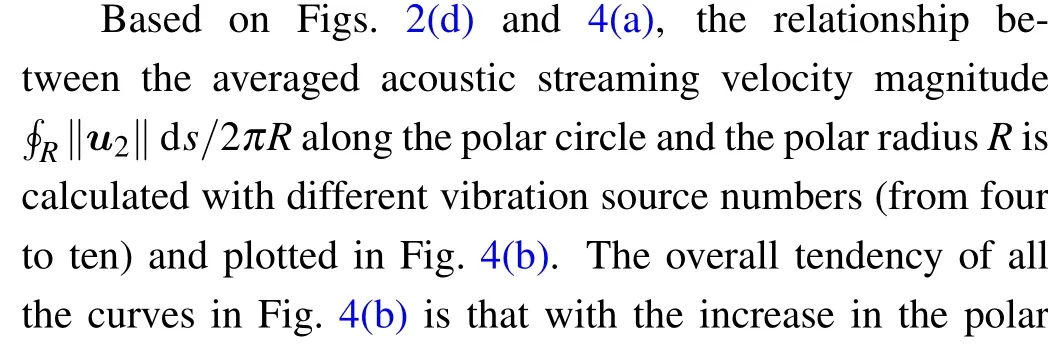
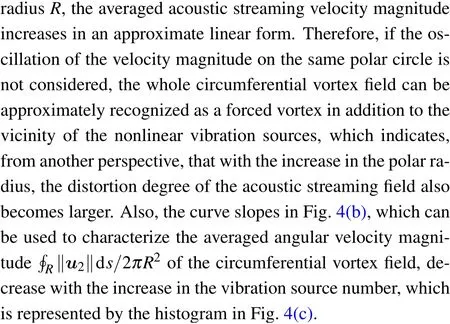
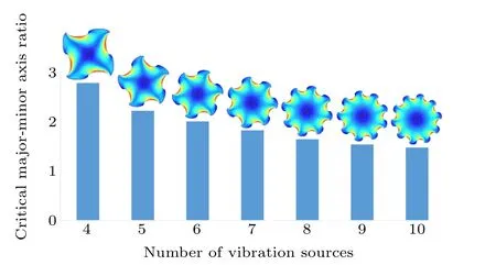
Fig.5. Critical major-minor axis ratios of semiellipses versus the number of vibration sources.
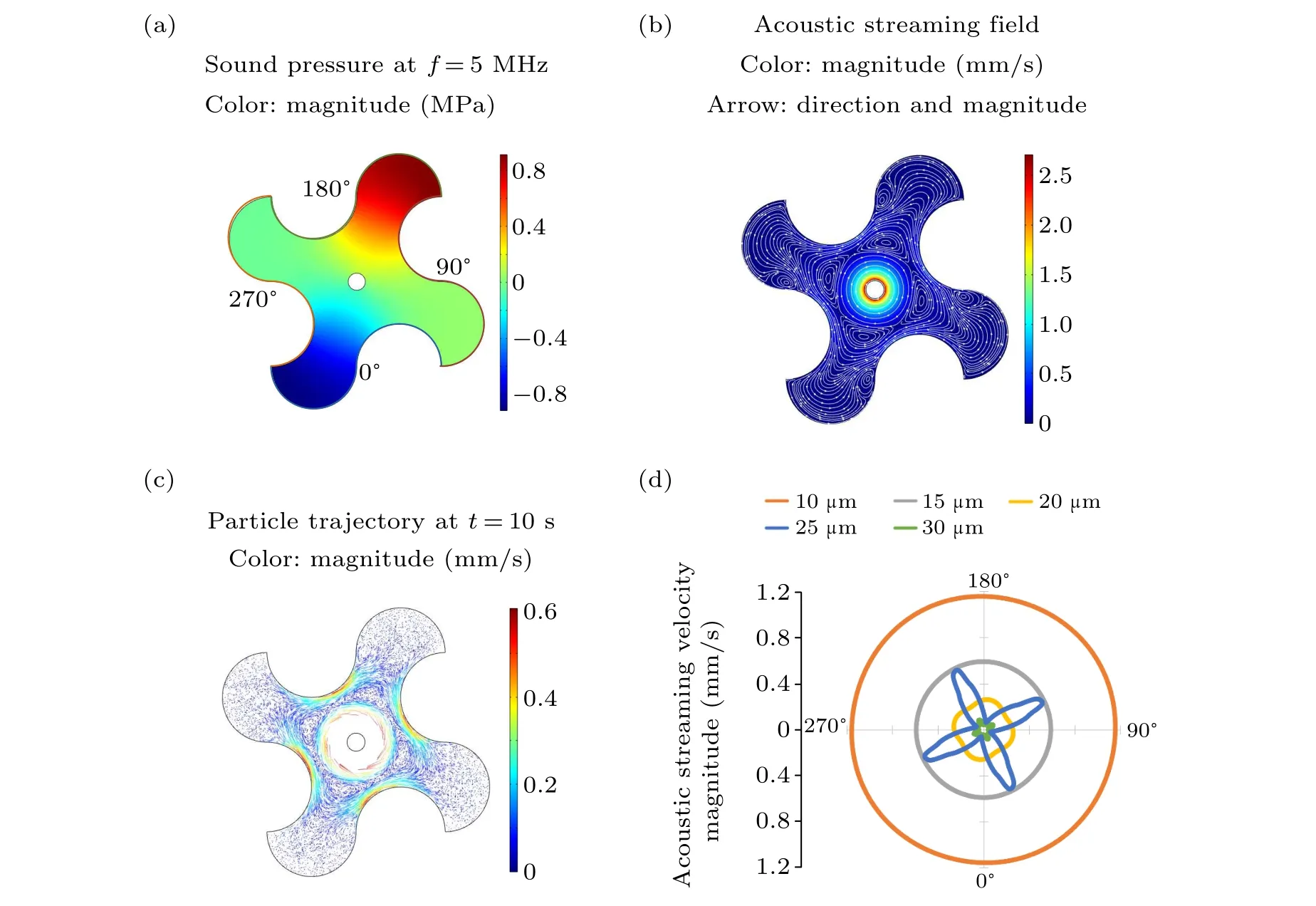
Fig.6. The acoustofluidic field and particle trajectory in the microfluidic chamber containing four nonlinear vibration sources and a circular obstacle. (a)The pattern of the sound pressure field. (b)The pattern of the acoustic streaming field. (c)The pattern of the micro-scale particle trajectory at a given time(10 s). (d)Curves of acoustic streaming velocity magnitudes at different polar radii.
From Figs.2(b)and 3(b),it can be found that local small vortices exist near the intersection region of concave and convex sides of each nonlinear vibration source, and these small vortices are generated due to the curvature of each nonlinear vibration source constructed by two semicircles. To achieve a single circumferential vortex field in the microfluidic chamber,two semiellipses, whose major-minor axis ratios are greater than 1, can be used to replace the previous semicircles. The calculated critical major-minor axis ratios versus different vibration source numbers are shown in Fig. 5, and the corresponding acoustic streaming patterns are also labeled in the figure. It can be clearly seen that, with the increase in the nonlinear vibration source number, the critical values of the major-minor axis ratio gradually decrease, which indicates that adding more vibration sources is beneficial for reducing the scale of small acoustic streaming vortices. One possible reason is the reduction of the vibration source size, and another reason for this is the consistency of the initial phase differences among neighboring vibration sources.
3.3. Acoustofluidic fields in different microchambers containing fixed obstacles
Based on the case with four vibration sources, a circular region with a radius of 5 µm is removed from the center of the microfluidic chamber to investigate the change in the acoustofluidic field and particle trajectory with fixed obstacles,and the simulated results are shown in Fig. 6. By comparing with Fig.2(a), it is found from Fig.6(a)that the existence of a circular obstacle has a noticeable effect on the distribution of the sound field in the form of sound reflection along the propagation path of acoustic waves,and the acoustic streaming vortices also change with the scattered sound field in the microchamber. The circumferential vortex field in the microfluidic chamber is destructed by the circular obstacle placed in the originally low flow rate area,resulting in a dramatic change in the flow-field distribution and a local maximum value of the acoustic streaming velocity magnitude around the obstacle. Also,four additional acoustic streaming vortices are generated between the nonlinear vibration sources and the circular obstacle,and the number of small vortices corresponds to that of vibration sources,as shown in Fig.6(b).Further calculation of the micro-scale particle trajectory in Fig.6(c)also indicates the change in the acoustofluidic field in the microchamber under the influence of the fixed obstacle. Due to the existence of a large circumferential flow rate, micro particles near the circular obstacle all move towards the vibration sources under the action of centrifugal force, thus generating a particle-free region with a diameter of about 30 µm in the microchamber center. Since the circumferential velocity near the vibration source surfaces is also relatively large,the agglomeration area of micro-scale particles can be formed between the vibration sources and the fixed obstacle,moving slowly under the action of four small acoustic streaming vortices. The velocity magnitudes of the acoustic streaming field along polar circles at different radii are also analyzed and plotted in Fig.6(d),which further indicates that the acoustic streaming velocity distribution near the obstacle is a high-speed circulation, while four small vortices are far away from the obstacle. Therefore, the inclusion of obstacles in the microfluidic chamber can be used for local removal and agglomeration of micro-scale particles.

Fig. 7. The acoustofluidic field and particle trajectory in the microfluidic chamber containing multiple nonlinear vibration sources and a circular obstacle. (a) The pattern of the sound pressure field. (b) The pattern of the acoustic streaming field. (c)The pattern of the micro-scale particle trajectory at a given time(10 s).
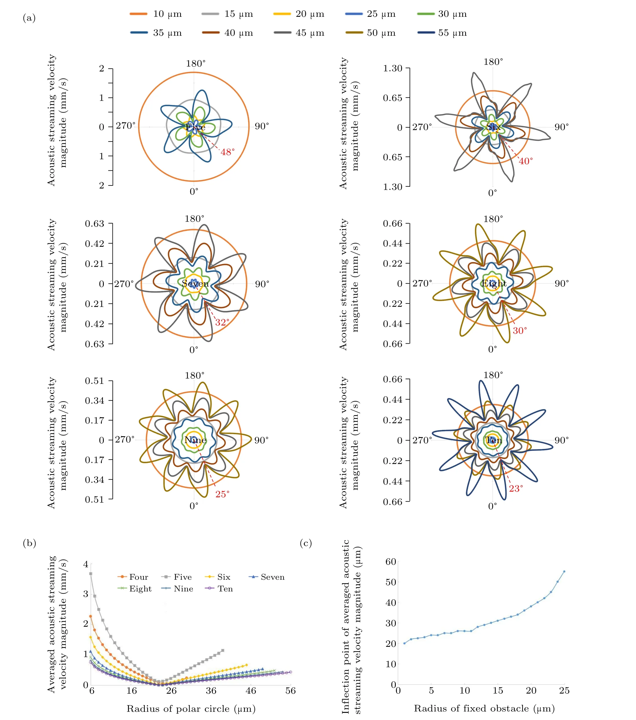
Fig. 8. Acoustic streaming velocity magnitudes under circumstances involving different vibration sources and circular obstacles. (a) Curves of acoustic streaming velocity magnitudes at different polar radii. (b) The averaged acoustic streaming velocity magnitude versus the radius of the polar circle. (c)The inflection point versus the obstacle radius.
The acoustofluidic field and particle trajectory at a given time (t= 10 s) in the microfluidic chamber composed of multiple vibration sources(from five to ten)and a circular obstacle are calculated in Fig.7. In contrast to Fig.6(a), all the sound field distributions in Fig. 7(a) are approximately antisymmetric with respect to initial phases of 0°and 180°,which indicates that the existence of the fixed obstacle has little influence on the sound field. The possible reason is that, with the increase in the vibration source number, the size of the microfluidic chamber and the distance between the vibration sources and the obstacle also increase. Similar to Fig.6(b),all of the acoustic streaming fields generated by multiple vibration sources (from five to ten) contain high-speed circumferential vortices near the fixed obstacles,as shown in Fig.7(b).However,with the increase in the vibration source number,the size of the local small vortices between the vibration sources and the obstacle gradually decreases, and all local acoustic streaming vortices eventually disappear. Therefore, in addition to all the boundaries set to be non-slip, there must be an annular region between the vibration sources and the obstacle, where the acoustic streaming velocity is almost zero when the vibration source number is larger than eight. The above conclusion can also be verified by the movement trajectory of micro-scale particles in Fig.7(c). Under circumstances involving five to seven vibration sources, there are polygonal regions without particles and particle agglomeration areas formed by local small vortices corresponding to the vibration source number in the microfluidic chamber. However,starting from eight vibration sources, the particle-free regions are approximately circular,and all the particles only move along the whole circumferential vortex field.
To quantitatively analyze the distribution of the acoustofluidic field generated by the combination of multiple vibration sources and fixed obstacles, the velocity magnitudes of the acoustic streaming field along polar circles at different radii are extracted and plotted in Fig.8(a). With the increase in the vibration source number, the influence range of non-petal-like circumferential circulation near the obstacle gradually increases, while the acoustic streaming velocity at the same polar radius decreases by degrees. Corresponding to the spatial distribution of multiple vibration sources,the velocity magnitudes near the sound radiation surfaces at different polar radii are all presented to be petal-like curves, and the petal number coincides with the number of vibration sources.By plotting red-dashed auxiliary lines, the polar angle values corresponding to the minimum velocity magnitudes around the vibration sources which first appear in the 1st quadrant are also measured and labeled in Fig.8(a). It is worth noting that,compared with Fig. 4(a), the polar values corresponding to these minimum velocity magnitudes do not change; that is to say,the existence of the circular obstacle in the microchamber center has little effect on the distribution of the whole circumferential vortices near the vibration sources and only changes the acoustic streaming velocity magnitude.Based on Fig.8(a),the relationship between the averaged acoustic streaming velocity magnitude∮R‖u2‖ds/2πRalong the polar circle and the polar radiusRis calculated with different vibration source numbers(from four to ten)and plotted in Fig.8(b). The overall tendency of all the curves in Fig. 8(b) is that, with the increase in the polar radiusR,the averaged acoustic streaming velocity magnitude decreases first in an approximate quadratic form and then increases in a nearly linear relation,and the inflection points of all curves are at the polar circle radius of about 24 µm, which indicates that no matter how many vibration sources there are,for circular obstacles with the same radius,the influence range of the averaged acoustic streaming velocity magnitude is almost the same. The relationship between the inflection point of the averaged acoustic streaming velocity magnitude and the size of the fixed obstacle is obtained from Fig.8(c). It is found that with the increase in the obstacle radius, the inflection point value increases first in an approximately linear and then in a quadratic form, indicating that the increasing rate of the inflection point value is first close to and then exceeds that of the obstacle radius.
In summary, by placing obstacles of different sizes at specific locations in a microfluidic chamber,local high-speed acoustic streaming vortices for particle removal or local lowspeed vortices for particle patterning can be generated near the fixed obstacles. Although the existence of obstacles has an impact on the overall distribution of the acoustofluidic field generated by multiple nonlinear vibration sources, there are invariant quantities of local acoustic streaming vortices within the influence range of the obstacle boundaries. In the following work,the structural design and topological optimization of embedded obstacles can be further carried out to obtain more diversified acoustofluidic fields for potential applications that include multi-functional controllable manipulation of micro-/nano-scale objects and efficient mixing of multiphase solutions.
4. Conclusion
In this paper, a novel method to generate diverse acoustic streaming vortices in a 2D microfluidic chamber, which is only actuated by normal vibration of nonlinear vibration sources with different initial phases, has been proposed and numerically investigated for potential applications that include microfluidic mixing and rotational manipulation of massive particles. It is found that the introduction of nonlinear vibration sources and fixed obstacles can cause spatial variations of the acoustofluidic field in the microchamber,which is beneficial to the realization of diversified modulation of acoustic streaming vortices in existing lab-on-a-chip devices. According to the simulation results of micro-scale particle trajectories under the combination of acoustic radiation forces and acoustic-streaming-induced drag forces,it is demonstrated that the rotational acoustic streaming field can not only accumulate micro-scale particles in the low-velocity region,but can also drive massive particles to rotate clockwise or counterclockwise along the circumferential vortices. The introduction of nonlinear vibration sources and obstacles offers the flexibility to modulate the acoustofluidic field in microfluidic devices for a variety of biomedical/engineering applications,which is expected to be a promising platform in the investigation areas of rapid medium/particle mixing on a microfluidic chip, local agglomeration/removal of micro-scale particles, and contactless/non-invasive manipulation of biological samples like cells or nematodes in a miniaturized total analysis system.
Acknowledgments
Project supported by the National Natural Science Foundation of China (Grant No. 11904117), the Industry-University-Research Collaboration Project of Jiangsu Province, China (Grant No. BY2019058), the Scientific Research Foundation of Huaiyin Institute of Technology (Grant No. Z301B19529), and the Training Foundation of Postgraduate Supervisor (Grant No. Z206E20555). Dr. Qiang Tang thanks the Jiangsu Government Scholarship for Overseas Studies.
猜你喜欢
Chinese Physics B(2022年10期)2022-10-26
Chinese Physics B(2022年10期)2022-10-26
电子乐园·中旬刊(2021年6期)2021-05-16
祝您健康(2020年9期)2020-09-08
蓝盾(2017年9期)2017-11-15
中外文摘(2017年19期)2017-10-10
当代工人(2015年1期)2015-03-10
新高考·高一物理(2014年1期)2014-09-18

- Chinese Physics B的其它文章
- Quantum walk search algorithm for multi-objective searching with iteration auto-controlling on hypercube
- Protecting geometric quantum discord via partially collapsing measurements of two qubits in multiple bosonic reservoirs
- Manipulating vortices in F =2 Bose-Einstein condensates through magnetic field and spin-orbit coupling
- Beating standard quantum limit via two-axis magnetic susceptibility measurement
- Neural-mechanism-driven image block encryption algorithm incorporating a hyperchaotic system and cloud model
- Anti-function solution of uniaxial anisotropic Stoner-Wohlfarth model