
High-sensitivity Bloch surface wave sensor with Fano resonance in grating-coupled multilayer structures
2022-04-12 03:46DaohanGe葛道晗YujieZhou周宇杰MengchengLv吕梦成JiakangShi石家康AbubakarBabangidaLiqiangZhang张立强andShiningZhu祝世宁
Chinese Physics B 2022年4期
Daohan Ge(葛道晗) Yujie Zhou(周宇杰) Mengcheng Lv(吕梦成) Jiakang Shi(石家康)Abubakar A.Babangida Liqiang Zhang(张立强) and Shining Zhu(祝世宁)
1Institute of Intelligent Flexible Mechatronics,Jiangsu University,Zhenjiang 212013,China
2National Laboratory of Solid State Microstructures,School of Physics,Nanjing University,Nanjing 210093,China
Keywords: lithium niobate,Bloch surface wave,Fano resonance,grating structure,biosensor
1. Introductio n
The optical surface resonance biosensor,[1,2]due to its real-time, label-free and nonselective detection,[3-5]is recognized to possess considerable potential applications in different research fields such as medical care, homeland security,environmental monitoring and biomedicine.[6,7]The mechanism of the surface resonance sensor is mainly based on the decay of full internal reflection (ATR),[8]where the electromagnetic waves decay along two different media and then form surface waves at the junction of the two interfaces. Currently, surface wave sensors are mainly concentrated in surface plasmon resonance(SPR)[9-13]and Bloch surface waves(BSW).[14-19]Similar to SPR, BSW can also be excited by coupling prisms,[14,15]nanoparticles[16]and gratings.[17-19]Also, BSW can be excited by different polarization states(P and S polarization) and any wavelength. As BSW does not use the precious metals, the resulting reflection spectrum curve is sharper,[20,21]quality factor higher and can be used for biosensing,[22]gassensing[23]and enhanced fluorescence emission.[24]
The photonic crystal plate[25]and distributed Bragg reflector (DBR) structure are widely used in present photonic crystal sensor designs. The DBR is a multilayer structure formed by alternating low and high refractive index (RI)media.[12-17,26]Here, a similar “sandwich biscuit” structure was used to build a DBR and introduce LiNbO3material to interrupt its structural periodicity. LiNbO3material was introduced due to its excellent piezoelectric effect and wide transparency range.Photonics crystals and Bragg gratings are some of the optical functions that can enhance the electro-optical and thermo-optical properties of LiNbO3-based devices.[27]Using the Pockels effect of LiNbO3, Bernal’s[28]research group has created an electro-optical tunable photonic crystal linear cavity on a 200 nm LiNbO3ridge waveguide to work in a slow light configuration. The electro-optical effect was founded to be enhanced by nearly 20-fold more than in bulk materials.Kovalevich[15]has introduced LiNbO3material and rotated the sample in such a way that light propagates along the ordinary or extraordinary axis. In that case,n0represents the ordinary RI andnerepresents the extraordinary RI of the lithium niobate film(LNF),which results in a 7°tunable difference.Devices based on LiNbO3materials have been widely used in sensors,[29,30]resonators,[31]optical modulators[32]and integrated optical components.[33,34]Compared to other top layer materials,[14,35-37]LiNbO3provides enhanced field confinement,[29]which can be further improved by using the thin films.[30]
A BSW device based on a LiNbO3grating-coupled with a DBR was proposed in this study. The rigorous coupledwave analysis (RCWA) method was used to discuss the influence of the field intensity distribution at different spatial incident angles and the extinction coefficient of each material on the performance of the BSW sensor. The designed sensor was adapted to two detection methods: surface diffraction and guided Bloch wave detections.The two modes were applied to the detection of gas and biological solution concentrations,respectively. The obtained results revealed the possibility of applying LiNbO3materials to BSW sensors for high-sensitivity sensing.
2. Design consideration and mathematical analysis
In this study,a Bloch device was designed that could support two detection methods, including surface diffraction and guided Bloch wave detections. The structural diagrams are shown in Figs.1(a)and 1(b),respectively.
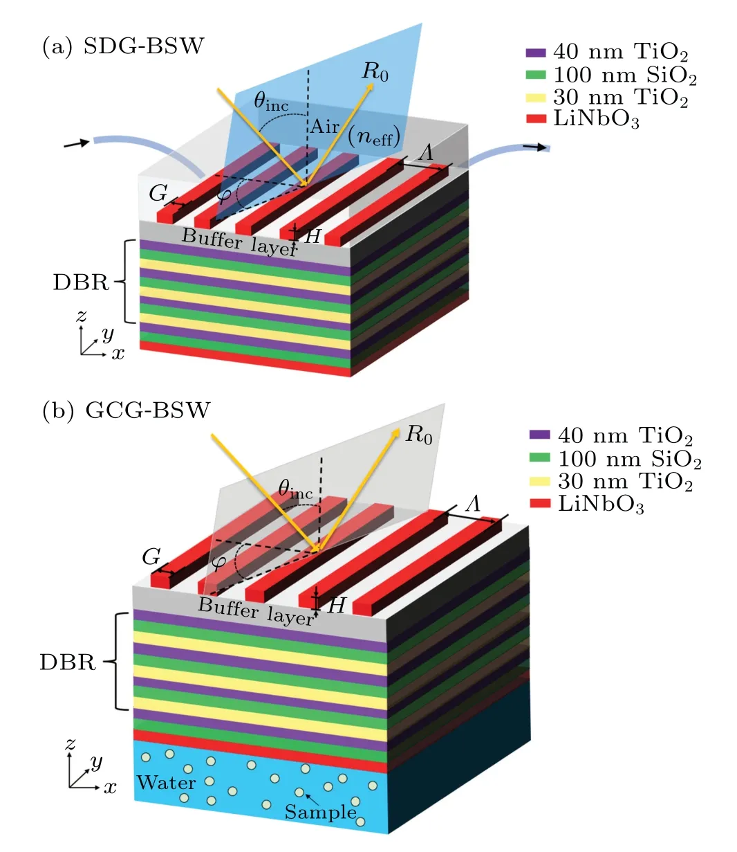
Fig.1. (a)Surface diffraction grating BSW design in(x-y-z)reference system. Structure includes few-period DBR, buffer layer, and grating.Coupling mediated by diffraction grating with period Λ =440 nm and thickness H =159.5 nm. External medium assumed as air (next =1).(b)3D schematic diagram of grating coupling guided BSW sensor under azimuthal illuminations (φ) in (x-y-z) reference system including incident angle (θinc), 0th-order reflection (R0), and grating parameters(Λ, f, and H). Sensing region located at bottom of grating coupling guided BSW sensor.
A sensor device was set up based on the azimuth sensitivity, with the azimuth angleφrepresented by the angle between thexaxis and projection of incident light on thex-yplane(Fig.1). In three-dimensional(3D)space,the direction of incident light propagation was expressed by the incident angleθ(the angle between the incident light andz-axis)and azimuth angleφ. A sensor device was designed here comprised of a DBR structure-coupled grating in the numerical simulation calculation. The DBR used in the design was composed of three-period, and the single-cycle structure was similar to a“sandwich biscuit”structure(ABA)3. The high RI material A was TiO2with an RI of 2.584, and the low RI material B was SiO2with an RI of 1.457. Then, a (A-B-LNF) pattern was used to break the periodic structure of the DBR, thereby forming a defect cavity. An LNF was anx-cut lithium niobate thin film(LiNbO3),which possesses a subwavelength grating structure.[38]Notably,a buffer layer was inserted between the DBR and subwavelength grating. The buffer layer was made of 160 nm low RI SiO2. The birefringence of the LiNbO3atλ=632.8 nm was expressed asne=2.2 andno=2.2885.The multilayer film was designed to support lateral electrical polarization of incident light in the visible light band,with the overall configuration referenced to Fig.1(a).The grating layer was designed to couple free-space wavelength incident waves into the Bloch surface mode. In the following simulation of analytical process, only the physical size of the grating (fill factorf,periodΛand thicknessH)and the incident light excited BSW under different spatial angles were described by the polarization and azimuth angles to optimize the reflection resonance peak curve.
After optimizing the grating results, the grating parameters were determined asf= 0.25,Λ= 440 nm andH=159.5 nm. When BSW was excited, the overall grating-Bragg reflector structure exhibited a sharp Fano resonance curve.[39,40]The Fano resonance curve drifted when the external environmental conditions changes, causing the RI of the detecting area to fluctuate. The device’s sensitivity was obtained by comparing the curve shift to the RI change. To achieve high-volume and low-cost production lines,the overall structure might be prepared by using a conventional microelectromechanical system(MEMS)process,which could also be combined into a biochip for detection of biological cells.In this case, the overall configuration of the device was used as given in an optical module Rsoft,which was calculated by using rigorous coupled wave analysis(RCWA).Reflection spectra and field distribution were computed with DiffractMOD,based on the software package Rsoft. The core algorithm,which was based on RCWA and enhanced with modal transmission line(MTL)theory, was a rigorous fully-vectorial solution of Maxwell’s equations. During the simulation,the periodic boundary conditions(PBCs)and perfectly matched layers(PMLs)were applied to the unit cell,which made a regular photonic crystal have extensibility and extend into infinite space.
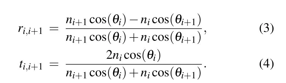
In addition,the transfer matrix method was used to obtain expressions of the optical properties of the multilayer sensing geometry, such as reflectance and transmittance.[41]The tangential component of the electromagnetic field between the boundaries was expressed by the formula

The transmission phase shift wasδi=2πnidicos(θi)/λ,which was determined by the incident wavelengthλ, layer thicknessdi, the RIni, and refraction angleθiof each structural layer. The refraction angle was determined by Snell’s law,as sin(θi)=n1sin(θinc). The Fresnel reflection coefficientri,i+1and transmission coefficientti,i+1of transverse electric (TE)polarization were given by Eqs.(2)and(3),respectively. The reflection(R)and transmission[42](T)were calculated asR=|M21|2/|M11|2andT=nm+1cos(θm+1)/(n1cos(θinc)|M11|2)with
3. Results and discussion
3.1. Surface diffraction grating-BSW detection mode(SDG-BSW)
The surface diffraction pattern detection was essentially guided by mode resonance(Fig.2(a)).[43-45]In subwavelength gratings,the eigenmodes existed as the solution of Maxwell’s equations in the periodic RI distribution.When the RI contrast between the grating ridge and air gap was large, the incident light not only excited the fundamental mode but also excited higher-order modes due to the large RI modulation. These modes were coupled to each other at the interface between the subwavelength grating and buffer layer. If these eigenmodes were in antiphase and canceled each other’s amplitude at the interface,the intensity of the transmitted light through the subwavelength grating became zero. When the RI of the external environment was 1, the TE polarization optical field distribution was obtained by using the spatial incidence angle(θ=21°andφ=4°).The field strength was concentrated at the grating groove and the local enhancement of theEyfield 11.06. After that,a spatial angle(θ=2.63°andφ=5°)of incidence was adopted and the field strength observed to have significantly decreased and concentrated at the junction of the buffer layer and grating (Fig. 2(b)). Notably, although the field enhancement factor obtained at this angle of incidence was 19.07,the object to be detected in air was not easily adherent to the grating/buffer layer,thus reducing the detection area of the sensor,compromising detection accuracy and lowering the detection limit and sensitivity of the BSW sensor.

Fig. 2. The calculated electric field distribution of TE polarized light at resonance, as the field intensity distribution diagram of SDG-BSW mode.Black dashed line represents the grating,buffer layer,DBR layer,and Y =0 represents x-z cross-section of the sensor. (a)Field distribution under incident angle(θ =21° and φ =4°). (b)Field distribution under incident angle(θ =2.63° and φ =5°).
3.2. Grating coupling guided-BSW detection mode(GCGBSW)
In the above analysis,changes in the spatial incidence angle was found to change the distribution of the field strength.Notably,the literature shows that changing the incident angle can change the photonic band gap of the Bragg reflector.[46-48]In this case,the incident light was divided into several diffraction orders(m=±1,±2,...),which provided additional momentumkm=kinc±mGfor the incident light required to couple to the BSW. In the formula,kmis the wave vector of the diffracted beam,kincequals tok0sin(θinc), the parallel component of the incident light wave vector,mis the diffraction order,Gequals to 2π/Λy, the grating wave vector, andΛyis the grating period. When the grating provided appropriate additional momentum,kmequalled tokBSWand BSW was excited.In this case,the grating was not only used to provide additional momentum,but also needed to be designed such that the normally incident EM wave was coupled to the BSW by receiving a reciprocal lattice vector. The BSW resonance led to the enhancement of the coupling diffraction order, and thus a high-quality Fano resonance.[39,40]in the scattering spectrum.
For this reason, the field intensity distribution of the device was altered by changing the spatial angle of the incident light to construct a guided Bloch wave detection. In the proposed scheme, the sensing area to the underlying LNF layer was transferred to avoid insufficient contact with the reactants due to the small reaction area of the grating grooves that further reduced the sensitivity of the BSW sensor (Fig. 1(b)).The basic configuration of the surface diffraction sensor device was followed in this sensing arrangement. Unlike the surface diffraction sensor,this sensor was placed on the upper layer of the area to be detected. Changes in the concentration in the area to be detected led to changes in RI.In addition,the incident space angle was adjusted, with the sensor placed on the upper layer of the sample solution whose RI was close to 1.333(pure water), where the thickness of the detection area of the sample solution layer was 3 µm. The evanescent properties of BSW in biological solutions showed that when the solution was thick enough,the thickness change of the sample solution layer had almost no effect on the Fano resonance in BSW.[3]Therefore,no further directed research was performed regarding sample solution thickness.
Fano resonance was created when visible TE polarized light with a wavelength ofλ=632.8 nm was irradiated on the grating surface from(θ=4.396°andφ=9.4°)by layerby-layer DBR transmission and total internalization reflection occurred when it reached the outermost LNF layer. The relationship between the incident and azimuth angle were examined in the space incident angle and the results clearly showed that each azimuth angle corresponded to the incidence angle.Also,BSW reflection intensity coupling occurred in the purple band with decreased reflection intensity(Fig.3(a)).Compared with the larger angular fluctuation of the azimuth angle,the angle change of the incident angle was only 0.2°,indicating that the Fano resonance in the BSW resonant peak was more sensitive to change of the azimuth angle relative to the incident angle. The electric field distribution was sampled and checked at the spatial angle(θ=4.396°andφ=10°;Fig.3(b)).It was clear from these results that the electromagnetic field entered through the grating andEyoscillated and propagated many times in the periodic DBR to generate five peaks. The peak in the LNF layer was the sharpest and the field strengthsEyand frequency(Hz)in this layer at maximum,with field enhancement factors of 39.88 and 54.22 (Figs. 3(c) and 3(d), respectively). Immediately afterward, the electromagnetic field intensity in the biological solution decayed exponentially along thez-direction. With the increased cut-off layer distance, the interaction between light and the solution decreased,with the BSW at 3µm penetration depth of the solution.
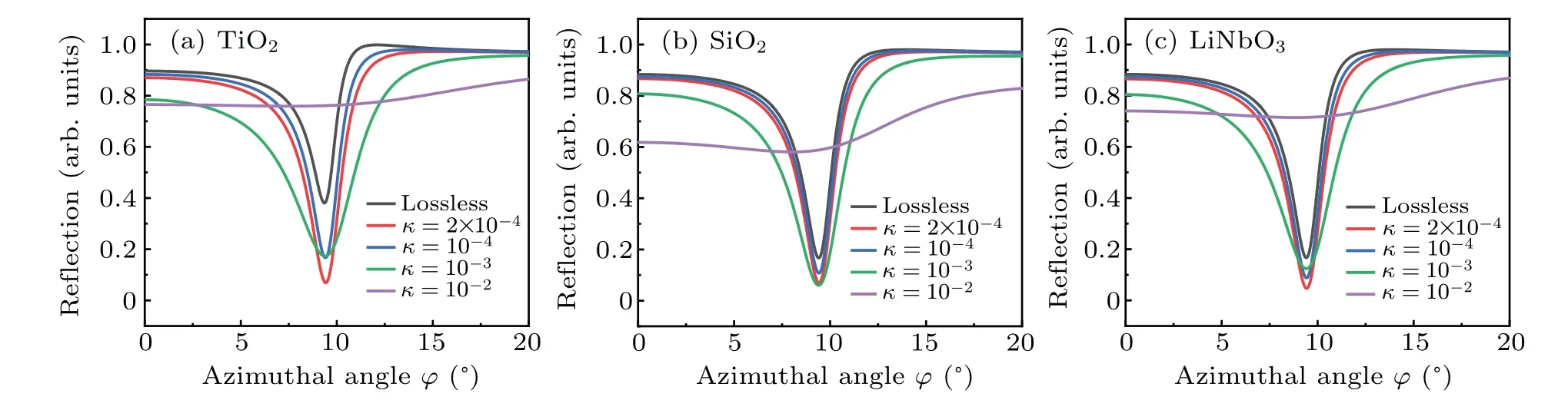
Fig.4. The influence of the extinction coefficient κ of each material in the GCG-BSW configuration on the reflectivity of the device. (a)TiO2,(b)SiO2,and(c)LiNbO3.
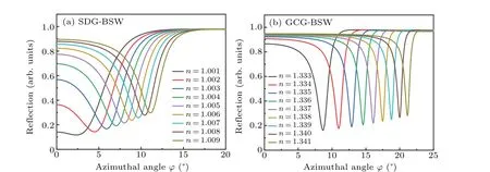
Fig.5. For solutions of different concentrations,the reflectance curve was a function of azimuth. (a)SDG-BSW and(b)GCG-BSW configuration.
All materials were set as nondestructive materials (zero extinction coefficientκ). For this reason, the dielectric loss for high RI(TiO2),low RI(SiO2),and LiNbO3materials was set,which was embodied in the imaginary part quantityκfor the material. The presence or absence of dielectric loss of all materials in the device is shown in Fig.4. The purple line indicates that the greater the material loss was,the less obvious the resonance dip peak was formed by the device.
The non-zero value, resonance dip peak depth and full width at half maximum (FWHM) formed by the nondestructive material were then compared and studied. The material had a certain extinction coefficient to help form a sharper dip peak. The lower the extinction coefficient of the high RI material and LiNbO3material was, the more obvious the Fano resonance and narrower the FWHM was obtained(Fig.4(c)).The loss of low RI materials also affected the overall light reflectivity of the device to a certain extent, but the effect was not as obvious as with high RI and LiNbO3materials. To be more practical,the extinction coefficient of each material was taken asκ=10-4.
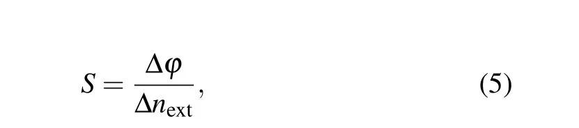
Sensitivity is a characteristic parameter that describes the sensitivity of sensor output and input,representing a criterion for evaluating a device’s quality. The present biosensor was essentially a RI sensor, which is usually designed to detect small RI modulations caused by changes in the concentration ratio of biomolecules. This sensor’s sensitivity was specified as
whereλis the resonance wavelength, representing the external medium RI,θis the angle of incidence andφis the azimuth angle. The FWHM was determined by calculating the full width of the half maximum of the reflectance curve at the half peak of the resonance dip,withHrepresenting the depth of the resonance peak,and the following formula was used to calculate the value of the quality factor FOM:

The corresponding peak drift in the surface diffraction detection mode was analyzed as well as the guided BSW detection mode when the external medium changed (Fig. 5).Changes in the external medium were reflected in RI changes.For the surface diffraction structure,the wavelength and incident angle were fixed at 632.8 nm and 21°, respectively, and for guided Bloch detection,the wavelength and incident angle were set at 632.8 nm and 4.9°, respectively. When the external refractive index increased uniformly,the resonance dip peaks formed under the two detection and sensing schemes all drifted at a small angle to a larger azimuth angle.
The FOM is another indicator to measure the performance of the sensor. It can be seen from the above Eqs. (5) and(6) that the two most critical parameters affecting the quality factor are FWHM andS. The FOM of many optical sensors is limited by the inherent balance between spectral sensitivity and FWHM. A linear fitting analysis on the two detection modes showed that the average sensitivity of the sensors obtained by analysis of the two modes was 1560°/RIU and 1161°/RIU, and the maximum detection sensitivity reached 2320°/RIU and 2200°/RIU,respectively(Fig.6(a)). Changes in the corresponding sensing characteristics between surface diffraction grating detection and guided Bloch wave detection were observed when the same variable Δnwas changed(Fig.6(b)). These results showed that they were all functions of the RI of the surrounding environment, and as the RI of the surrounding environment changed,the FWHM and sensitivity presented a linear relationship with Δn. The sensitivity and quality factor were substantially enhanced compared to sensors in the literature.[16,36]The ultra-high quality factor indicates that the BSW absorber was suitable for biosensing and gas sensing.

Fig.6. (a)Linear regression analysis between the resonance angle and RI of the analyte at the specified position in SDG-BSW mode(left)and GCG-BSW mode(right).(b)Sensing characteristics of GCG-BSW(red bar)and SDG-BSW(blue bar)configurations, with the value of sensitivity calculated by simulation with Δn.
4. Conclusions and perspectives
The overall aim of this study was to explore a means for coupling LiNbO3material coupled with a photonic crystal to construct a label-free detection platform and detect RI changes in the external medium by stimulating the BSW. A thin film and grating structure composed of LiNbO3material were deposited on both sides of a DBR,which was composed of different RI media. A rigorous coupled-wave analysis method was used to carry out the numerical analysis, and the influence of the loss of each material on the sensor analysis was studied in detail. The distribution of the electromagnetic field strength of the sensor was explored and found to change with changing incident angle in different spaces. For this reason,two detection and analysis modes were set up for this sensor,including surface diffraction detection and guided Bloch wave detection. According to the drift of the Fano curve, the average sensitivity of the sensors was 560°/RIU and 1161°/RIU,and the maximum detection sensitivity at 2320°/RIU and 2200°/RIU,respectively. Compared with sensor sensitivities in the literature,[16,36]these sensor sensitivities were greatly improved,providing a new solution for LiNbO3-coupled DBR for exploring Bloch surface wave devices.
Acknowledgements
Project supported by Natural Science Foundation of Jiangsu Province, China (Grant No. BK20180098) and National Laboratory of Solid State Microstructures,Nanjing University(Grant No.M33042).

- Chinese Physics B的其它文章
- Quantum walk search algorithm for multi-objective searching with iteration auto-controlling on hypercube
- Protecting geometric quantum discord via partially collapsing measurements of two qubits in multiple bosonic reservoirs
- Manipulating vortices in F =2 Bose-Einstein condensates through magnetic field and spin-orbit coupling
- Beating standard quantum limit via two-axis magnetic susceptibility measurement
- Neural-mechanism-driven image block encryption algorithm incorporating a hyperchaotic system and cloud model
- Anti-function solution of uniaxial anisotropic Stoner-Wohlfarth model