
Reconstruction resolution enhancement of EPISM based holographic stereogram with hogel spatial multiplexing
2022-04-12 03:46YunpengLiu刘云鹏TengZhang张腾JianSu苏健TaoJing荆涛MinLin蔺敏PeiLi李沛andXingpengYan闫兴鹏
Chinese Physics B 2022年4期
Yunpeng Liu(刘云鹏) Teng Zhang(张腾) Jian Su(苏健) Tao Jing(荆涛)Min Lin(蔺敏) Pei Li(李沛) and Xingpeng Yan(闫兴鹏)
1Department of Information Communication,Army Academy of Armored Forces,Beijing 100072,China
266132 Troop of the Chinese People’s Liberation Army,Beijing,China
396669 Troop of the Chinese People’s Liberation Army,Beijing,China
4Department of Basic Education,Army Academy of Armored Forces,Beijing 100072,China
Keywords: holography,holographic stereogram,hogel spatial multiplexing
1. Introduction
A holographic stereogram is an effective form of reconstructing a 3D scene and is a focus point in 3D imaging.[1-7]The traditional holographic stereogram is usually composed of multiple hogels,which are square areas on the holographic stereogram, and each of which records a parallax image.Since the angular resolution of the human eyes is about one arcminute,[8]when the viewing angle interval of the adjacent parallax image sequence of the holographic stereogram is less than the angular resolution of the human eyes, a limited parallax image sequence can be used to approximate the continuous light field distribution of a 3D object. In essence, the holographic stereogram approximates the continuous wavefront of the object to some wavefront segments. If the length of the wavefront segments is small enough, we can reconstruct the object’s original wavefront to obtain a more realistic holographic reconstruction. Sanget al.proposed a novel display method to realize a natural 3D scene with high quality reconstructed images.[9]A set of active partially pixelated masks are used to direct the views to the eyes, and then the observer can move freely in the viewing area and experience the real 3D scene. Another way to reduce the disparity between the wavefront segments and the object’s original wavefront is to add missing phase information to the holographic stereogram,which can increase the human eyes’perception of the depth of the 3D scene. In 2015, an algorithm based on a fully computed holographic stereogram for calculating fullparallax computer-generated holograms(CGHs)with accurate depth cues was proposed by Caoet al.[10]In their work,wavefront segments closer to the original wavefront were created,and computer graphics rendering techniques were employed in the CGH generation to enhance the image fidelity. There is no restriction on the form of printed objects in the holographic stereogram. They can be real objects or virtual models. As long as there is view image data of the 3D scene, 3D objects can be reconstructed. Because the fabrication of a holographic stereogram does not need complex forward diffraction of the object wavefront nor the interference calculation between the object wavefront and the reference light, the number of samples required for a 3D scene can be small, which means that less time is required compared to computational holography.In addition,the laser power requirement is reduced when printing hogels. Furthermore, multiple hogels can be printed in parallel to construct a largescale hologram,thereby yielding a high printing efficiency. The above characteristics make the holographic stereogram technology widely used in military,commercial,art,and other fields.[11]
Fabrication of a hogel is the key to holographic stereogram technology. The shape and size of a hogel are related to the aperture’s shape and size and to the moving step size of the holographic recording medium in the printing system.The size and shape of the hogel have a considerable influence on the reconstruction of the holographic stereogram. As early as 1994, Hilaire[12]described the modulation transfer function’s behavior with respect to factors such as image depth,resolution, and perspective window size, and concluded that an optimum scene reconstruction and considerable savings in computation time could be achieved by choosing an appropriate hogel size. In 2006, the concept of the sampled modulation transfer function of the holographic stereogram was proposed by Helseth.[13]This function could be determined by the shape,size,and transmittance of the hogel,and optimizing the amplitude and phase filters can improve the optical resolution. In 2013,Jianget al.[14]investigated the influence of different shaped windows on the optical transfer function(OTF)of holographic stereogram systems. Their analysis showed that the shaped exit pupil function,with optimized hogel size,can effectively improve the imaging quality of full-parallax holographic stereogram systems. In 2018, Suet al.[15]established the exit pupil function model of the effective perspective image segmentation and mosaicking method (EPISM) based on a holographic stereogram, and then optimized the hogel size with a certain depth distribution of the 3D scene to improve the imaging quality. In 2020, Yanet al.established a diffraction limited imaging model of a hogel based holographic stereogram. They found that view-flipping reduction and reconstruction resolution enhancement for EPISM based holographic stereograms can be achieved when the properly sized hogel is utilized.[16]
In traditional holographic stereogram printing, a square holographic pupil is typically used, and the adjacent splicing method is adopted, that is, the moving step size of the holographic recording medium is equal to the side length of the aperture. When the moving step size is less than the aperture’s side length,the holographic exposure area of each step is overlapping.In 2013,Honget al.[17]proposed a hogel overlapping method for the holographic stereogram. Experimental results showed that multiple perspective images recorded by overlapped hogels do not influence each other, and the proposed method has improved the lateral resolution of holographic stereograms compared to the conventional method.The multiplexing encoding method was proposed and demonstrated for accurate reconstruction by using a single phase only spatial light modulator.[18]Three-dimensional(3D)images can be reconstructed clearly when the light waves at different wavelengths are incident into the encoding hologram. However,there is no relevant research on why hogels can realize spatial multiplexing at the same wavelength and correctly reconstruct the 3D scene. Further theoretical analysis and experimental verification are required to determine the direct impact of lateral resolution on the reconstructed image and the reconstruction characteristics of overlapping methods.
In this work, the spatial multiplexing method of hogel is used to improve the reconstruction resolution of holographic stereograms. First, we introduce the theoretical basis for the correct reconstruction by hogel spatial multiplexing,which is based on the principle of holography and Bragg’s diffraction theory of crystals. The diffraction efficiency of the reconstructed image is analyzed in detail by nonoverlap and overlap printing. Afterward, the space-bandwidth product theory of holographic stereograms is proposed, and we explain the influence of the increased lateral resolution of hogel spatial multiplexing printing on the reconstructed image’s quality. Finally, experimental results verify our theoretical predictions,and demonstrate that hogel spatial multiplexing printing can significantly enhance the reconstruction resolution of EPISM based holographic stereograms.
2. Analysis on hogel spatial multiplexing
2.1. The splicing strategy between adjacent hogels
There are two ways to fabricate a hogel. One is to control the size and shape of the exposure area by placing apertures on both sides of the holographic recording medium, the other is to control the size and shape of the scattered light spot through the lens with a high numerical aperture and holographic diffractive optical elements that control the exposure range. In this study, we employ the first method. As shown in Fig.1,the aperture is an opaque metal plate with a specific shape,and two apertures are placed on both sides of the holographic recording medium to control the size and shape of the hogel. The object beam emitted from the LCD panel loaded with the perspective image and scattered by the diffusor then interferes with the reference light on the other side of the aperture. The interference pattern is recorded to a specific area of the holographic recording medium under the limitation of the apertures. Then,the holographic recording medium is moved by a 2D linear track to complete the exposure of other areas.In the conventional holographic stereogram printing process,the moving step sizeΔPis equal to the side length of the square apertureΔH, and the exposure area is neither overlapped nor missed, as shown in Fig. 2(a). When the moving step size of the linear track is less than any value of the aperture size,the exposure areas are overlapped. However, only when the moving step size can divide the aperture size exactly,i.e.,the moving step size is 1/Nthe aperture size,whereNis a positive integer,the printed hogel is“tight”. In other words,removing the edge of the holographic stereogram can achieve uniform multiple exposures and completely cover the central part of the holographic stereogram. Figure 2(b)shows the case ofN=2.Here, the adjacent hogels are overlapped, except for the edge part of the holographic stereogram. Moreover, each overlapping area is a square area with a side length of the moving step size, which is exposed four times, and four adjacent perspective images can be recorded and reconstructed. Similarly, for other values ofN,no matter what the value ofNis,the size of the overlapping part isΔP,and each area is exposedN2times,andN2perspective images are recorded.

Fig. 1. Structure diagram of fabricating hogel in holographic stereogram printing system.

Fig.2.Different hogel splicing strategies:producing(a)tight junctions,(b) uniform overlapping, (c) nonuniform overlapping, and (d) uncompact junction.
When the moving step size cannot divide the size of the aperture, the exposed part of the holographic stereogram is not uniform. The size of each exposure area is different, and the number of perspective images recorded is also different.As shown in Fig. 2(c), the hogels are not “close” together or overlapped, i.e., the moving step size cannot divide the aperture size exactly. Therefore, the exposure of the holographic recording medium is not uniform, and the hologram can be divided into three areas. The first is a square area with side lengthΔP,and only one perspective image is recorded as R1.The second is also a square area with side lengthΔH-ΔP,and four adjacent perspective images are recorded as R2. The last one is a rectangular area in lengthΔPand widthΔH-ΔP,and two adjacent perspective images are recorded as R3.
The nonuniform overlapping of a hogel will cause the brightness of the light entering the pupil to flicker when the viewing position changes. This is manifested by the low brightness of the unexposed part or the part with low exposure, and the high brightness of the part with high exposure.In addition, when the exposure exceeds the sensitivity of the holographic recording medium, the reconstruction brightness decreases due to overexposure. When the moving step size is greater than the side length of the aperture, as shown in Fig.2(d),i.e.,ΔH<ΔP,the holographic recording medium is not fully utilized, and there is an unexposed part between the hogels. It can be reasonably assumed that the resulting loss in the reconstructed image’s visual angle, when the holographic stereogram is observed such that the reconstructed image is discontinuous,seriously affects the observation experience.
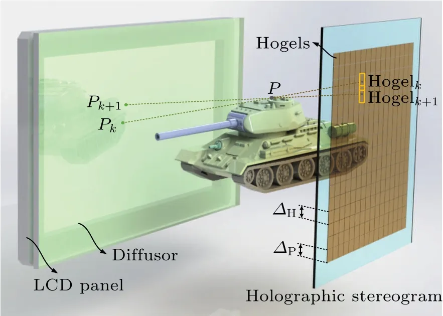
Fig.3. The reconstruction configuration of holographic stereogram.
The reconstruction configuration of the holographic stereogram is shown in Fig.3.The hogel size is denoted asΔH,and the moving step size of the holographic recording medium isΔP. Consider an object at pointPlocated on the tank canopy,and that there are two hogels,hogelkand hogelk+1,located on the hologram plane. Their center points are connected with pointP,and the extension line intersects with the LCD panel at pointsPkandPk+1. The pointsPkandPk+1are two adjacent reconstructed image points of pointP, representing two different directions of reconstructed light emitted from the position of pointP. The distance between pointsPkandPk+1determines the viewing angle interval of adjacent parallax image sequences,and thus directly impacting the view flipping of the holographic stereogram. The smaller the distance between pointsPkandPk+1,the weaker the view-flipping effect. It can be seen from Fig.3 that the distance between adjacent reproduction image points is related to the geometric relationship among the 3D objects, the LCD panel, and the holographic stereogram, as well as the moving step size of holographic recording mediumΔP, but not to hogel sizeΔH. Therefore,it can be inferred that spatial multiplexing printing can reduce the view-flipping effect by reducing the spacing between hogels.
2.2. Multiple exposure in hogel spatial multiplexing
The essence of holography is to record the fringes generated by the interference between the wavefront of the original 3D scene and the reference beam into the holographic recording medium, and to then illuminate the processed recording medium with a light source in a specific direction to reconstruct the original scene. Some of the most common recording mediums for optical holography are silver halide emulsion,photoconductive plastics,light polymer,and photorefractive materials. Silver halide emulsion is used as the recording medium in our laboratory. Taking silver halide emulsion as an example, we analyze the physical essence of hogel spatial multiplexing that can produce the correct reconstruction.
When the recording medium’s thickness is much larger than the interference fringes, the interference fringes form a complex 3D volume grating structure in the recording medium:
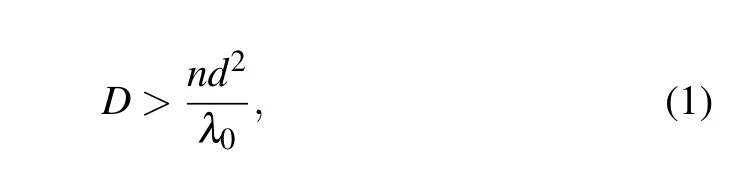
whereDis the thickness of the emulsion,generally 15µm,nis the refractive index of the emulsion after developing and fixing,λ0is the wavelength of the reconstructed light in vacuum,anddis the period of the interference fringes. To simplify the analysis, the distribution of the interference layer is considered when two beams interfere. The angle between the object beam and the reference beam is recorded asφ, and the interference layer is as shown in Fig.4(a). The distribution of the interference layer is parallel to the angular bisector of the propagation direction of the two beams. The amount of exposure depends on the intensity and the phase difference between the two beams of light.When the two beams have the same phase,their light intensity after interference is enhanced. When the phase is opposite, the light intensity is weakened. The equal exposure plane is parallel to the angular bisector of the reference light and the object light,and the silver atoms inside the silver halide emulsion are evenly distributed to form a silver layer, that is, the distribution of the silver layer is also parallel to the angular bisector of the reference light and the object light. According to the Bragg condition, only the light consistent with the direction of the original reference light can be enhanced in the process of interference. The light is reflected by multiple silver layers in the direction of the original object light, which reconstructs the object light exactly, as shown in Fig. 4(b). The reflected light from other directions is eliminated after interference, which realizes the selection of object light direction in holography. The illuminated beam must strictly meet the Bragg condition,otherwise the brightness of the reconstruction will be extremely low.[19]In addition, according to the theory of wave optics,the object light wave with arbitrary complex amplitude distribution can be composed of infinitely many plane waves with different directions. Therefore, the simplified analysis case can be correctly extended to the complex case where the complex amplitude distribution of object light is arbitrary. In the hogel spatial multiplexing method,the selectivity of the complex 3D volume grating structure in the recording medium to the object light direction is the physical basis for reconstructing the 3D scene exactly from the multiple exposure regions.
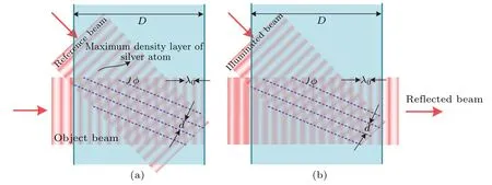
Fig.4. Silver layer of holographic recording medium: (a)the distribution of silver,(b)selectivity and reflection of illuminated beam by the silver layer.
2.3. Diffraction efficiency of hogel spatial multiplexing
According to the definition of general diffraction efficiency, we can define the diffraction efficiency of the holographic stereogram, which is the ratio of the average brightness of the reconstruction to the brightness of the illuminated beam. To simplify the analysis, we only consider the case in which the holographic recording medium is exposed uniformly. The effect of multiple exposures on the diffraction efficiency of a hologram should be considered when using the hogel spatial multiplexing method. The diffraction efficiency of multiple exposure holograms has been analyzed in detail, and the diffraction efficiency of conventional printing and hogel spatial multiplexing printing is compared.
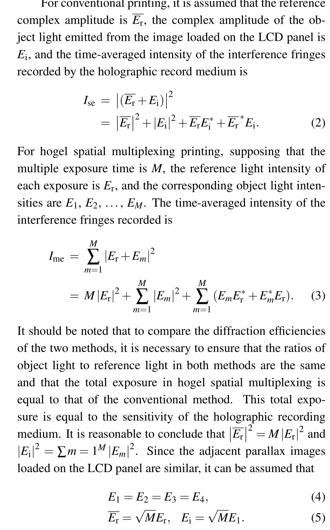
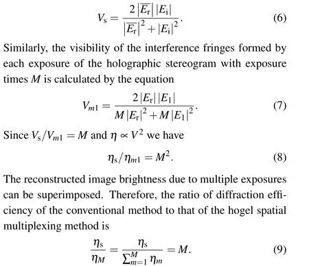
The first term in Eqs.(2)and(3)are both a constant,i.e.,the exposure generated by the reference light corresponds to the background light reconstructed. The second term is the exposure produced by the object light,which is a nonuniform term,and it corresponds to halo light and is also the main source of noise. The last two terms represent the fluctuating exposure,which correspond to the real image and virtual image. The diffraction efficiency is proportional to the square of the visibility of the interference fringes,i.e.,η∝V2,whereηdenotes the diffraction efficiency of the holographic stereogram,andVis the visibility of interference fringes inside the holographic stereogram.
The visibility of interference fringesVis defined as twice the amplitude of the wave term divided by the sum of the uniform term and nonuniform term. According to Eq. (2), the visibility of interference fringes in conventional printing is
When the moving step size is 1/Nof the aperture size, the holographic recording medium is exposedN2times except for edge areas. According to Eq.(9),the diffraction efficiency of the hogel spatial multiplexing method is 1/N2times the value of a single exposure. A largerNcan significantly affect the holographic stereogram’s diffraction efficiency,which reduces the reconstructed image’s brightness. The thickness of the silver halide emulsion used in this paper is about 15µm,and the diffraction efficiency can be more than 90%when the ratio of object/reference is 1:1 and the incident light direction is 30°from the normal of holographic recording medium. Using the beam of the same brightness and direction to illuminate the holographic stereogram, the brightness of the reconstruction printed by the above-mentioned two printing methods directly depends on their own diffraction efficiencies.
2.4. Spatial bandwidth product theory of EPISM holographic stereogram
The spatial bandwidth product (SBP) is often used to evaluate an optical imaging system’s quality, and represents the amount of information transmitted by the imaging system.For a 2D optical imaging system, the larger the spatial bandwidth product is,the better the optical imaging system is,according to the extended relationship
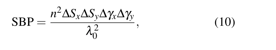
wherenis the refractive index of the medium,λ0is the wavelength of the light wave,ΔSx,yis the visualxandyspace range of the system,Δγx,yis the aperture angle(which is limited by the aperture),and Δγ/λ0is the bandwidth.
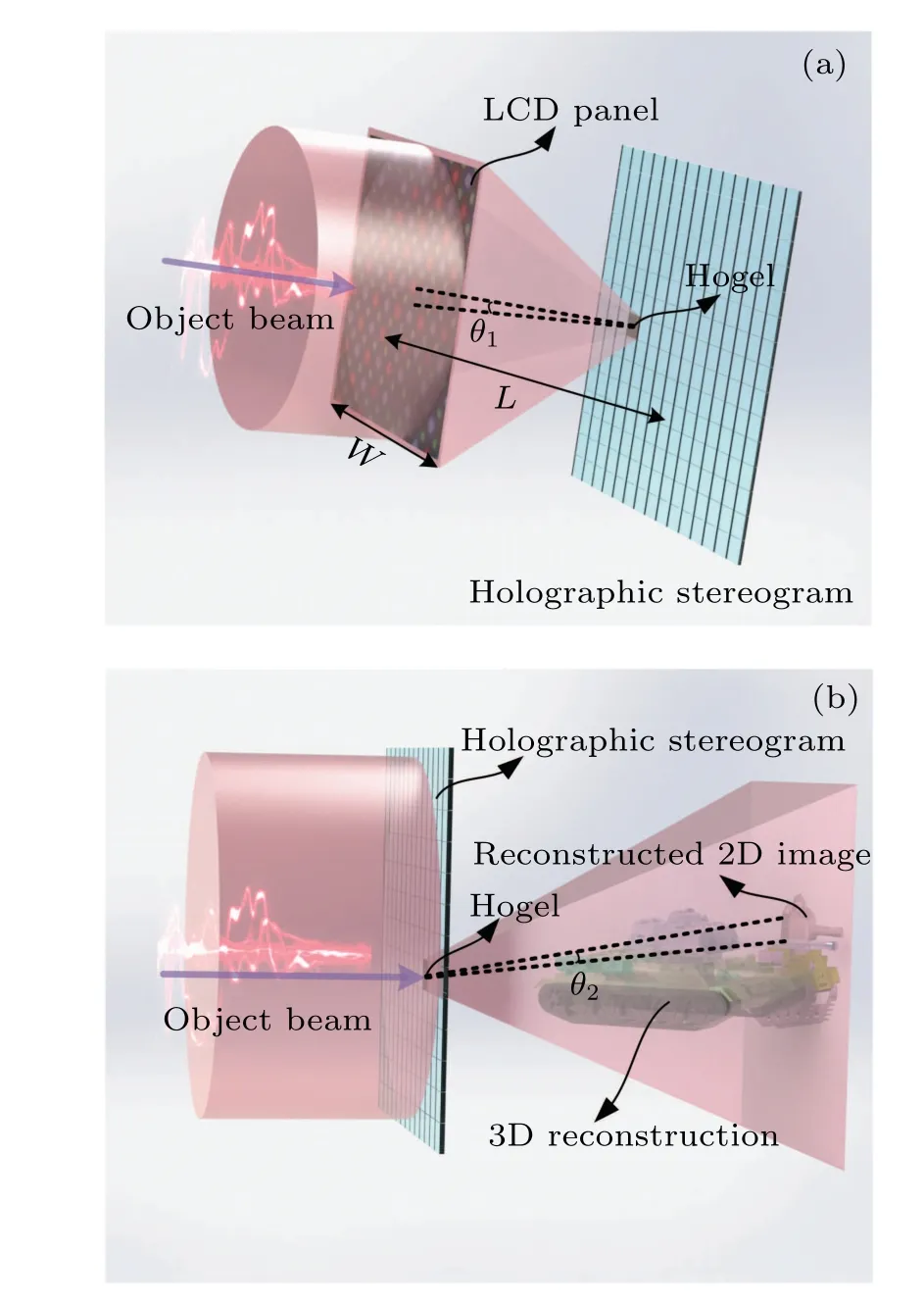
Fig.5. The spatial angular resolution during(a)holographic recording,and(b)holographic reconstructing.
A holographic stereogram can be regarded as a special optical imaging system. It reconstructs a 3D scene from multiple 2D images with continuous viewing angles. The quality and quantity of 2D images will affect the reconstructed image.The quality of 2D images is related to the spatial angular density(Ωx,y)of reconstructed light,and the larger theΩx,y,the better the reconstructed-image quality. Similarly,the quantity of 2D images is related to the spatial density of hogels (Hx,y), and the greater theHx,y, the better the reconstructed image. The product ofΩx,yandHx,yis proportional to the total amount of information in the holographic stereogram. Analogously, the amount of information transmitted by the full-parallax holographic stereogram imaging system can be defined as
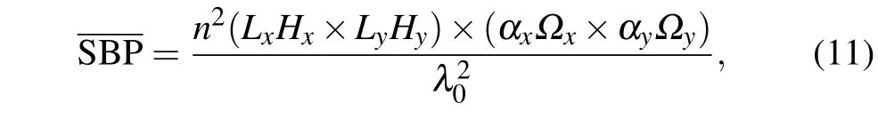
whereLx,yis the size of the holographic stereogram inxandydirections,αx,yis the field of view of reconstruction,the spatial density of the hogel’sxandydirections is denoted asHx,y,and the spatial angular density of reconstructed light alongxandydirections is denoted asΩx,y.
The spatial density is easy to calculate:it is defined as the reciprocal of the moving step size of the holographic recording medium,i.e.,H=1/ΔP. The spatial angular density is the reciprocal of the spatial angular resolution. To calculate the spatial angular density, the effects of holographic recording and reconstruction on the spatial angular resolution should be considered. The higher limit of the two processes determines the spatial angular resolution of the reconstructed image.
During holographic recording, the size and resolution of the perspective image loaded on the LCD panel and the distance between the LCD panel and the holographic stereogram are the factors that affect the spatial angular resolution. As shown in Fig. 5(a), assuming that the size of the perspective image isW,the resolution isX,and the distance between the LCD screen and holographic plate isL. The spatial angular resolution of the holographic recording is the angle between two adjacent pixels on the LCD panel and the center of the hogel as expressed by
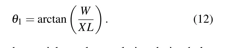
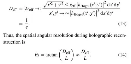
Here,θ1describes the spatial angular resolution during holographic recording. However, the diffraction angle caused by the finite aperture determines the spatial angular resolution during holographic reconstruction,as shown in Fig.5(b). According to our previous research,the size of the dispersion spot can be defined using power in the bucket (PIB) method. The effective resolvable size is
In our lab’s holographic stereogram printing system,the resolutionXof the perspective image loaded on the LCD panel is 1000×1000,and the sideWis 10 cm.The distanceLbetween the LCD screen and the holographic plate is 15 cm. According to Eq.(12), the spatial angular resolutionθ1during holographic recording is 6.67×10⁴radian. Furthermore, according to Eqs. (13) and (14), the theoretical spatial angular resolutionθ2of the reconstruction at different defocus distancesLPand hogel sizeΔHcan be calculated. The spatial angular resolutionsθ1andθ2are shown in Fig.6.
When the defocus distance equals zero, i.e.,LP=0, the spatial angular resolutionθ2decreases to zero with an enlarged hogel size. WhenLP/=0,the curves describing the spatial angular resolutionθ2are similar, and an optimal hogel sizeΔHcan be achieved whereθ2is minimized.This is because,under a smallΔH,the diffraction effect plays a dominant role onθ2.However,whenΔHis large enough,the influence of the defocused aberration also plays an important role. The horizontal line depictingθ1intersects with the curve depictingθ2at one or two points, and the larger values of the horizontal lineθ1and curveθ2determine the reconstructed image’s spatial angular resolution.
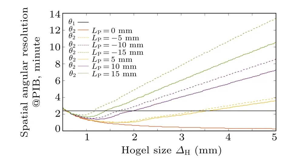
Fig.6. Spatial angular resolutions θ1 and θ2.
When the structural parameters of the two compared printing systems (i.e., the hogel spatial multiplexing method and the conventional method)are the same except for the moving step sizeΔP,the former method has the same spatial angular density of reconstructed light as the latter since theΔHof both methods are the same.However,the spatial density of the hogel can be increased by decreasingΔP.Our method does not reduce the size of hogels,is not aggravated by the influence of diffraction effects on reconstruction,maintains the spatial angular resolutionθ2,and increases the SBP of the holographic stereogram imaging system. For a full-parallax holographic stereogram, hogel spatial multiplexing occurs inxandydirections at the same time so that the SBP of both directions increases,which leads to a greater increase in SBP.
However, it is impossible to improve the quality of the reconstructed image endlessly by using a smaller moving step sizeΔP. A smallerΔPwill lead to increasing the number of exposures on the same area, which will decrease the brightness of the reconstruction and degrade the quality of the reconstructed 3D scene. Meanwhile, a smallerΔPrelates to a smaller boundary-distance of the hogel, and these grid-like boundaries will result in notable diffraction whenΔPis small enough.[20]In the grating equation d sinΔφ=kλ,d=ΔPdenotes the distance between two adjacent boundaries,k= 1 denotes the first diffraction order, Δφdenotes the diffraction angle, andλrepresents the wavelength. If the diffraction angle of the hogel boundaries equals the physiological resolution of the human eyes, i.e., Δφ=1',[18]the inferior limit of the moving step size will readΔP≈2 mm. This is also the reason whyΔPis set to 2 mm in the following experiment (see Section 3.3). However, in practice, Δφ=1'is such an exact criterion that the minimum angular resolvable limit of the human eyes can be relaxed to some extent,for example,Δφ=3'can be employed, and thus the distance between two boundaries is approximately 0.7 mm. In other words, whenΔPis less than 0.7 mm, the grating diffraction effect of the boundary grid on the incident light will substantially deteriorate the reconstructed image. Hence,0.7 mm can be chosen as one of the criteria for the selection ofΔP. Furthermore, the printing time will also increase rapidly when the moving step sizeΔPis too small.
3. Results and discussion
3.1. Sampling geometry
An optical experiment was conducted to verify the theoretical prediction. The geometric relationship is shown in Fig. 7. The length of the tank model is about 40 mm, and the width is about 25 mm. The tank’s center is 150 mm from the hologram plane and 300 mm from the camera plane. The 3DStudio MAX is applied to render the perspective images.Then,129×129 perspective images are obtained with the resolution of each 1000×1000. These perspective images are resynthesized with EPISM to generate the effectively synthetic perspective image. The resolution of the effectively synthetic perspective image is 1000×1000.

Fig. 7. Configuration of sampling and geometrical parameters for the generation of effectively synthetic perspective images.
3.2. Experimental setup for printing the full-parallax holographic stereogram
The experimental setup is illustrated in Fig.8. A continuous wave 400 mW 639 nm single-longitudinal-mode linearly polarized solid-state laser (model CNIMSLFN639@CNI) is used as a light source. The light beam passes through the shutter and the firstλ/2 wave plate, and then enters the polarization-dependent beam splitter. A shutter is used to control the on-off state of the light path. The light beam is divided into a reference beam and an object beam after passing through the polarization-dependent beam splitter. The light beam’s polarization direction can be changed by rotating the first wave plate to change the object beam’s light intensity and the reference beam. Research shows that the closer the ratio of object light to reference light is to 1:1, the higher the diffraction efficiency is. In fact, the reference light intensity is much higher than the object light. Therefore, the firstλ/2 wave plate is often rotated to the position where the object light intensity is the largest. The reference light is reflected into the attenuator through a reflector, and then is reflected in the spatial filter through another reflector, which aims to filter the high frequency noise of the beam. The lens of the spatial filter is 40×, and the pinhole size is 15 µm. After passing through the collimating lens, a parallel beam reference light with a radius of 2 cm and an intensity of 300 µW is obtained. However,the object light passes through the secondλ/2 wave plate and enters the 40× objective lens. This light is diffused into a beam with a radius of about 10 cm,and then illuminates the LCD panel loaded with the synthetic parallax image. The object light with light field information propagates freely in space, most of it is blocked by the aperture,while a small part of it interferes with the reference light on the other side. The object light intensity reaching the holographic recording medium is about 12.5µW.The interference fringes are recorded inside the holographic recording medium,and a square hogel is formed. The light intensity of the silver halide plate is ΔE=1250 µJ/cm2at 639 nm. In the printing system,a microcomputer is used to synchronously control the shutter’s opening and the two-dimensional linear track movement(model KSA300@Zolix)to realize the exposure of multiple hogels. The positioning accuracy of the two-dimensional linear track movement is less than 2.5 µm and the resolution of reconstructed image is tens of micrometers. Thus, the positioning accuracy hardly affects image mosaicking precision.Thex-ylinear tracks cooperate with each other to complete the printing of all hogels row by row or column by column. The time consumed to print a hogel is usually the sum of exposure time and waiting time. The exposure time is light intensity divided by the sum of reference light and object light intensity,i.e.,1250/(300+12.5)=4 s. The waiting time is about 16 s,and this is the waiting time for the vibration of the displacement platform to stop. Printing a holographic stereogram with 256 hogels takes about 1.25 h. In the traditional method, the size of the holographic stereogram is 6 cm×6 cm and consists of 15×15 hogels with a size of 4 mm. It took about 1.25 h to fabricate the whole holographic stereogram. In our hogel spatial multiplexing method,the holographic stereogram consists of 30×30 hogels with a size of 4 mm,and printing took about 5 h. Considering the huge time cost,we only compare the results ofN=1 andN=2. Improving the printing efficiency is one of our next steps. The printing system is redesigned with a high numerical aperture lens group and holographic diffractive optical element as the core. The holographic diffractive optical element is a kind of micro nano optical element that can control the shape of the scattered light spot along with the size and shape of hogels. Thus,we can verify the impact of a smallerΔPor largerNon reconstruction.

Fig.8. Experimental setup for printing the full-parallax holographic stereogram by the conventional method and hogel spatial multiplexing method.
3.3. Experimental results and discussion
Figures 9(a)-9(i)show the reconstruction following traditional printing,in which the hogel size is 4 mm.Figures 10(a)-10(i)show the reconstruction of tank model with different angles of hogel spatial multiplexing, in which the size of hogelΔHis 4 mm, and the moving step sizeΔPis 2 mm. In order to prove the superiority of hogel spatial multiplexing,the virtual tank model shown in Fig. 7 is used as the 3D object. A group of control experiments was conducted to compare the traditional printing method and the hogel spatial multiplexing method. The only controlled variable was the moving step sizeΔP. We keep the side length of the square apertureΔHas 4 mm, andΔPas 4 mm and 2 mm. Canon5D Mark III is used to capture the reconstructed images. It is equipped with a Canon RF 70-200 mmf/2.8L IS USM lens. The reconstruction following traditional printing is shown in Figs.9(a)-9(i),where the image is focused on the tank canopy. It can be seen that the reconstructed 3D scene has an acceptable definition on both the canopy and track but has remarkable blur on the tank’s barrel. This is because the tank canopy and track are closer to the geometric center of the tank, i.e.,LP≈0 mm.According to the analysis in Subsection 2.4,the spatial angular resolution is mainly determined by spatial angular resolutionθ1during holographic recording, and this is close to the angular resolution of the human eyes(1'). However, the tank barrel is about 15 mm away from the geometric center of the tank, i.e.,LP≈15 mm. According to the green solid line in Fig.6, the spatial angular resolution is mainly determined by spatial angular resolutionθ2during holographic reconstructing. In this case, it is far beyond human eyes’ resolution,at about 8'. This greatly reduces the reproduction resolution of the tank’s barrel. Compared with the traditional printing method with the same parameters, for the object points either located near or far away from the tank’s geometric center,their reconstructions appear relatively higher definition (see Fig. 10). Specifically, the track of the hogel spatial multiplexing method is more detailed than that of the traditional printing method. The reason for this is that the number of reconstructed perspective images is increased inxandydirections while the resolution of reconstructed images is not reduced. Moreover,the number of hogel spatial multiplexing method is four times that of the traditional printing method,which has a higher spatial density of hogels. Additionally,the hogel spatial multiplexing method greatly improves the SBP of the holographic stereogram imaging system, and confirms the theory presented in Subsection 2.4. When dynamically observing the reconstructed image while changing the viewing angle,it can be found that the view-flipping effect for the tank’s barrel is stronger than that of the tank’s canopy and track with the traditional method.This is an inherent shortcoming of the holographic stereogram. However,the hogel spatial multiplexing method can reduce this view-flipping effect of the barrel to a certain extent by reconstructing more 2D perspective images.In general,the hogel spatial multiplexing method produces reconstructed images with slightly lower brightness,but with smoother motion parallax and higher resolution. Overall,our method can greatly improve the reconstruction quality of the holographic stereogram.

Fig.9. Reconstruction with the conventional method. (a)-(i)Reconstructed perspective images perceived at nine different angles of views.

Fig.10. Reconstruction of the hogel spatial multiplexing method. (a)-(i)Reconstructed perspective images perceived at nine different angles of views.
4. Conclusions
We have analyzed different hogel splicing strategies and the effect of multiple exposures on the diffraction efficiency of reconstruction, and explained why our hogel spatial multiplexing method can reconstruct the 3D scene correctly, and the adverse effect of multiple exposures on the brightness of reconstructed image is predicted in advance. We construct an SBP model of the holographic stereogram imaging system to comprehensively evaluate the influence of optical element parameters and experimental setups of the printing system on the resolution of reconstructed images in both holographic recording and reconstructing processes.Our theoretical analysis predicts that the hogel spatial multiplexing method can improve reconstruction by enlarging the spatial density of hogels and keeping the spatial angular density of reconstructed light. Experimental results agree well with the theoretical analysis.The hogel spatial multiplexing method produces reconstructed images with lower brightness. However, due to the smoother motion parallax and higher resolution of the reconstructed image, the reconstruction quality of the holographic stereogram is greatly improved.Meanwhile,the decrease in hogel interval reduces the view-flipping effect and enhances resolution, but leads to a significant increase in the time it takes to fabricate the holographic stereogram. For example,the fabrication time is increased by four times if the hogel interval is diminished by half. We note that only experiments with the moving step size at 1/2 the aperture size were conducted in this study. Thus,our proposed method has not been verified for larger values.Whether multiple exposures seriously affect the diffraction efficiency of the holographic stereogram has not been confirmed.These will be investigated in the future.
Acknowledgements
This work was supported by the National Key Research and Development Program of China (Grant No. 2017YFB1104500), the National Natural Science Foundation of China (Grant No. 61775240), and the Foundation for the Author of National Excellent Doctoral Dissertation of China(Grant No.201432).

- Chinese Physics B的其它文章
- Quantum walk search algorithm for multi-objective searching with iteration auto-controlling on hypercube
- Protecting geometric quantum discord via partially collapsing measurements of two qubits in multiple bosonic reservoirs
- Manipulating vortices in F =2 Bose-Einstein condensates through magnetic field and spin-orbit coupling
- Beating standard quantum limit via two-axis magnetic susceptibility measurement
- Neural-mechanism-driven image block encryption algorithm incorporating a hyperchaotic system and cloud model
- Anti-function solution of uniaxial anisotropic Stoner-Wohlfarth model