
Strong chirality in twisted bilayer α-MoO3
2022-04-12 03:44BiYuanWu吴必园ZhangXingShi石章兴FengWu吴丰MingJunWang王明军andXiaoHuWu吴小虎
Chinese Physics B 2022年4期
关键词:王明
Bi-Yuan Wu(吴必园) Zhang-Xing Shi(石章兴) Feng Wu(吴丰)Ming-Jun Wang(王明军) and Xiao-Hu Wu(吴小虎)
1School of Automation and Information Engineering,Xi’an University of Technology,Xi’an 710048,China
2Shandong Institute of Advanced Technology,Jinan 250100,China
3School of Optoelectronic Engineering,Guangdong Polytechnic Normal University,Guangzhou 510665,China
4School of Physics and Telecommunications Engineering,Shaanxi University of Technology,Hanzhong 723001,China
Keywords: chirality,twisted bilayer,α-MoO3
1. Introduction
Chirality means that an object cannot coincide with its mirror image through any rotation or translation operation,which is widespread in nature.[1-3]Like human hands,the left hand does not overlap with the right hand that mirrors each other.The chiral enantiomers in drugs have the same chemical formula and physical properties,but they have different spatial arrangement. However, this asymmetry can lead to inactivity or even toxicity.[4]For example, the thalidomide incident in history results from insufficient understanding of chirality.[5]Therefore,it is very desirable to strengthen the ability to recognize the chiral objects.
The conventional technical means for distinguishing chiral structures is to measure the absorptivity/transmissivity spectra of their interactions with circularly polarized wave.[6]The difference in absorptivity/transmissivity between the lefthand circular polarization (LCP) and the right-hand circular polarization (RCP) is defined as circular dichroism (CD).Once the circular dichroism is detected, the chirality can be well judged. However, naturally occurring chirality is very weak, which would not only lead to the low sensitivity of measurement technology, but also result in the waste of materials and long acquisition time. Realizing the strong chirality is of critical importance in applications such as analytical chemistry,[7]polarization optics,[8-11]and biological sensing.[12-15]To obtain the strong chirality, many effective methods have been proposed.[16-21]Wanget al.designed a chiral structure combining bilayer of anisotropic metamaterial structures. Moreover,in that work it was proposed and proved that the destroying of the rotational and mirror symmetry simultaneously is the necessary condition for chiral structures through the framework of Jones calculus.[22]Their work provides a convincing theoretical basis for designing chiral structures. Based on Ref.[22],various bilayered chiral nanostructures have attracted great attention and been designed.[23-33]For example,Donget al.proposed a chiral metamaterial composed of square-periodic array pairs of mutually twisted metallic crosses separated by dielectric layer.[34]Although the giant circular dichroism can be excited in chiral metamaterials,the fabrication of three-dimensional(3D)metamaterials is not easy.
In fact, the chiral response can be excited in the nanostructures with in-plane anisotropy. If there is a material with in-plane anisotropy itself, it will greatly simplify the chiral structures. Theα-MoO3is a kind of naturally biaxial hyperbolic crystal with intrinsic in-plane anisotropy.[35-39]Furthermore, the fabrication ofα-MoO3films is easier than that of 3D metamaterials. Chemical vapor transport technique with low cost is often used to fabricate it. Theα-MoO3has attracted a great deal of attention in recent decades for its profound applications in various disciplines, such as radiation heat transfers[40-42]and plasmonic biosensors.[43]Recently,Wuet al. studied extrinsic chirality resulting from the relative orientation of theα-MoO3film and the incident light in a singleα-MoO3film,[39]where the CD (about 0.77) is still not strong enough. Combining with the viewpoint of the literature,[22]an idea about chirality based on the twisted bilayer structure comes into our mind. Very recently, Linet al.realized chiral plasmons in van der Waals heterostructures comprised of twisted atomic bilayers,[44]which is determined by the interlayer quantum coupling. Stauberet al.investigated the chiral response in twisted bilayer graphene,[45]and the chiral character is associated with a longitudinal magnetic moment.Besides,the CD in Ref.[45]is extremely small(smaller than 0.001).
In this paper, we systematically investigate the chiral response of the twisted bilayerα-MoO3. The thickness values of twoα-MoO3slabs and the relative rotation angle between them are the two main parameters affecting the CD. In order to enhance the chirality of the structure,we optimize these parameters according to two methods. It is found that the CD of the structure can reach 0.89. Furthermore, the polarization conversion is calculated to reveal the underlying physical mechanism, which is completely different from the counterparts in Refs. [44,45]. Finally, the influence of the relative rotation angle and the angle of incidence on CD are studied as well.
2. Modeling and methods
Figure 1(a)schematically shows the model to be studied in this paper. The structure consists of two layers ofα-MoO3with a relative rotation angle to break the overall mirror symmetry. In the figure,d1andd2are the thickness of the top and bottomα-MoO3, respectively, andδrepresents the relative rotation angle between the twoα-MoO3slabs. The light incident is along thezdirection. For the bottomα-MoO3slab,crystallographic axes [100], [001], and [010] are along thex,y,andzdirections,respectively. Thus,the permittivity tensor can be expressed asε=diag(εx,εy,εz). The expressions ofεx,εy,andεzare described by the Lorentz equation[46]as follows:
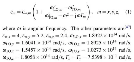

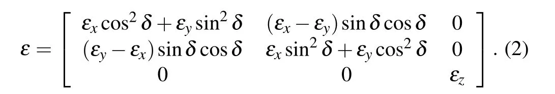

Fig. 1. (a) Schematic diagram of twisted bilayer α-MoO3, (b) real parts of the principal permittivities of α-MoO3.
The transfer matrix method (TMM) is used to calculate the transmissivity of the proposed structure.[47]According to Jones vector, elliptically polarization wave is defined as follows:
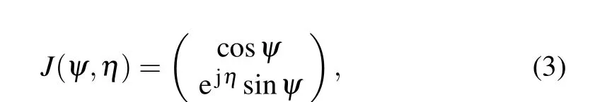
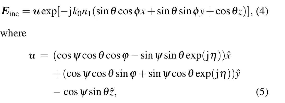
whereψis the angle between the incident plane and the electric field vector,andηis the phase difference between the electric fields parallel and perpendicular to the plane of incidence.The incident electric field is defined as wheren1andn2represent the refractive index of incident medium andα-MoO3slab, respectively,φis the azimuthal angle,andθrefers to the wave incidence angle.
The electric field in the incident medium(z <0)and that of transmitted wave(z >d=d1+d2)are calculated from

wherek0is the wavevector in vacuum,k1,zandk2,zare the wavevector component along thezdirection inz <0 andz >d,respectively. The electromagnetic fields in anyα-MoO3slab are given by
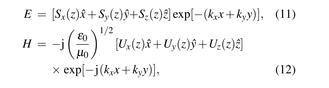
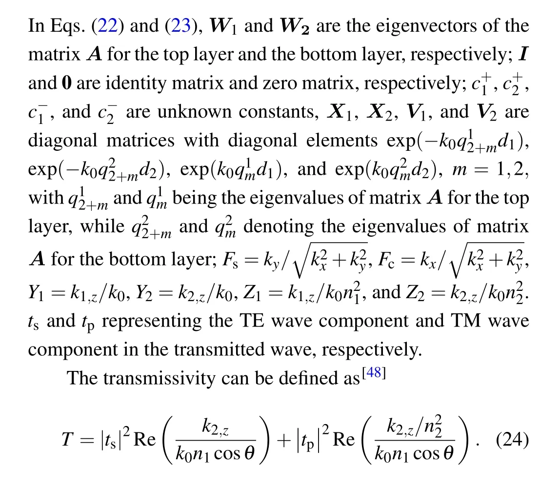
whereSx,Sy,Sz,Ux,Uy,andUzare the amplitudes of electromagnetic field components.ε0andµ0represent the permittivity and permeability of vacuum, respectively. Supposing that the permittivity tensor of one anisotropic slab is
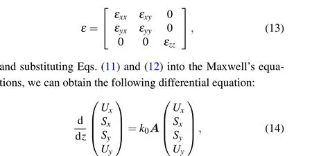

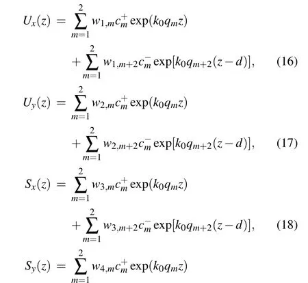
whereKx=kx/k0andKy=ky/k0. For the bottom layer, theεxyandεyxare both equal to zero. For the top layer,εxyandεyxare non-zero complex numbers related to the rotation angleδ,which can be found in Eq.(2).By calculating the matrixA,we can obtain the eigenvaluesqmand the eigenvector matrixW. The tangential electromagnetic field components are described as

3. Results and discussion
The CD is a vital parameter to measure the chiral response,which is equal to the difference in transmissivity(absorptivity/reflectivity)between LCP wave and RCP wave. We take the transmissivity into consideration in this work. Hence,the CD can be obtained from
whereTLCPandTRCPare the transmissivity for LCP wave and RCP wave,respectively.
Figure 2 shows the curves of transmissivity as a function of wavelength,respectively,for LCP wave,RCP wave and the corresponding CD under normal incidence. Here the relative rotation angle is fixed at 45°. The thickness values of the top and bottom slabs are both 1 µm. It can be seen that the relatively large CD appears at the wavelengths of 14.4 µm and 20.3µm. Since the rotational symmetry and mirror symmetry have been destroyed simultaneously by the relative rotation between the two layers,the twisted bilayerα-MoO3is a chiral structure.
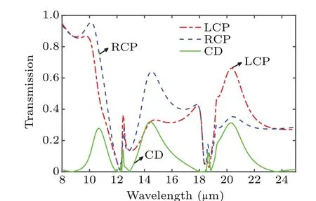
Fig. 2. Transmissivity spectrum for LCP wave (red line), RCP wave (blue line), and the corresponding CD(green line)under normal incidence, with relative rotation angle fixed at 45°.
Taking wavelengthλ=14.4µm for example,we further enhance the CD at this wavelength. Two parameters can affect the CD,which are the thickness values of two slabs, and the relative rotation angle between them. Here, we optimize first the thickness and then the relative rotation angle. When the relative rotation angle is 45°,the transmissivity as a function ofd1andd2is plotted in Fig. 3(a) for LCP wave and in Fig.3(b)for RCP wave. Obviously,the transmissivity has the periodic enhancement with the increasing of thicknessd1andd2for both LCP wave and RCP wave. The phenomenon originates from Fabry-Per´ot(FP)resonance. When thed1(ord2)equals zero,the model is simplified into a free standing singleα-MoO3slab. The circularly polarized wave can be decoupled into TM wave and TE wave. Besides, both of them can excite the FP resonance. The quantization condition for any two adjacent orders of FP resonances can be described as
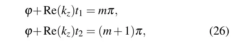
whereφis the reflection phase at the interface between the air and theα-MoO3slab,t1andt2are the thickness of theα-MoO3slab when the two adjacent orders of FP resonances occur, respectively,mis an integral number,kz=nk0, withnrepresenting the refractive index andk0=2π/λwith wavelengthλ. Therefore,the difference(Δt=|t1-t2|)in thickness of theα-MoO3slab between the two adjacent orders of FP resonances can be calculated from
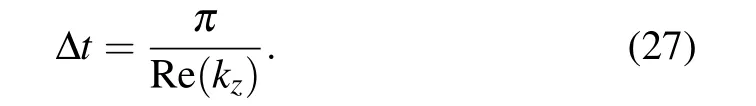
It is worth noting that theα-MoO3possesses different refractive indices in three principal directions since it is an anisotropic material. In our simulation, we define the plane of incidence as thex-zplane. Thus, the electric field vector is parallel to theyaxis for the TE wave, while thexaxis is for TM wave under normal incidence. According to Eq.(27),Δtis equal to 2.28 µm and 2.75 µm for TM wave and TE wave when the wavelengthλis 14.4 µm, respectively. The results are in good agreement with the scenarios in Figs.3(a)and 3(b). Back to Fig. 3, for RCP wave, it is found that the transmissivity is enhanced periodically with the increase ind2when the thicknessd1is less than 1 µm, while the transmissivity is small at the same thickness under the illumination of LCP wave. Figure 3(c)shows the corresponding CD.One can see that the CD improves periodically asd2increases, which comes from FP resonance as well. In addition,the CD reaches its maximum value when the thickness of top layer and bottom layer are 0.8µm and 3.4µm,respectively.
Based on the above optimization results (d1= 0.8 µm andd2=3.4 µm), the influence of the relative rotation angle on circular dichroism atλ=14.4 µm is discussed. Figure 4 shows the transmissivity under the illumination of LCP wave, RCP wave and the corresponding CD as relative rotation angle increases from 0°to 90°.One can see that the CD is zero when the relative rotation angle equals 0°. When the relative angle becomes bigger,the CD increases gradually at first and reaches its maximum at 57°, then drops down to nearly zero when relative rotation angle approaches to 90°. Since the bilayer structure we proposed with relative rotation angle 0°or 90°possesses the rotational symmetry or mirror symmetry, the chiral response disappears. In addition, it is found that the maximum CD is smaller than 0.5. In order to acquire the stronger circular dichroism, the parameters of the model should be further optimized.
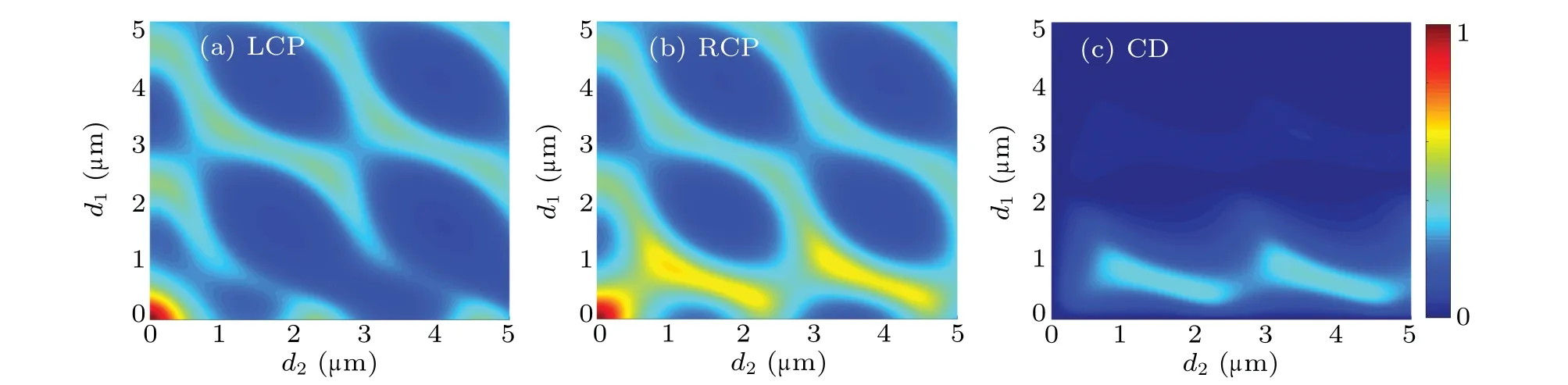
Fig.3. Transmissivity as function of thickness of top slab d1 and bottom slab d2 at wavelength 14.4µm when relative rotation angle is 45°,for(a)LCP wave,(b)RCP wave,and(c)corresponding CD.

Fig.4. Curves of transmissivity versus relative rotation angle for LCP wave(red line), RCP wave (blue line), and corresponding CD (green line) when thickness d1 and d2 are 0.8µm and 3.4µm,respectively.
Here, we optimize first the relative rotation angle, and then the thickness. Considering different relative rotation angles,we plot the curves of CD as a functions of thickness for the two slabs as shown in Fig.5. It is found that the CD is extremely small at any thickness when the relative rotation angle is 10°, and the CD rises with relative rotation angle increasing. The results show that the CD can be flexibly tuned via changing the relative rotation angle between the two layers. In addition,one can see that the CD reaches its maximum value when the relative rotation angle is 70°. Therefore,we further optimize the relative rotation angle around 70°by using the same method, but the results are not shown here. It is found that the CD can reach a maximum value of 0.89 at a relative rotation angle of 75°when the thickness of the bottom slab and the top slabs are 2.72µm and 0.6µm,respectively.
Now,at the optimized parameters(φ=75°,d1=0.6µm andd2=2.72 µm), the transmissivity spectra and CD spectra are investigated and shown in Fig. 6. At a wavelength of 14.4µm,a large transmissivity can be observed for RCP wave while the transmissivity is almost zero for LCP wave. One can see that the CD can reach 0.89,indicating a strong chirality.

Fig.5. Variations of CD with thickness of top slab d1 and bottom slab d2 at different relative rotation angles: (a)10°,(b)20°,(c)30°,(d)40°,(e)50°,(f)60°,(g)70°,and(h)80°.
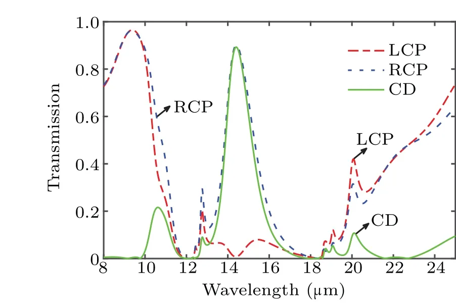
Fig. 6. Transmissivity spectrum for LCP wave (red line), RCP wave (blue line), and the corresponding CD (green line), with relative rotation angle being 75°, and top slab and bottom slab 0.6µm and 2.72µm in thickness,respectively.
To better illustrate the underlying physical mechanisms of the strong chirality, the polarization conversion curves for LCP wave and RCP wave under normal incidence are shown in Fig.7. When circularly polarized light with different handedness is incident on the structure,the transmitted wave contains the components of both LCP wave and RCP wave. For the incident RCP wave, the amplitude of LCP wave in the transmitted wave is greater than 0.4 at a wavelength of 14.4 µm,and the amplitude of RCP wave reaches 0.5. However, both LCP wave and RCP wave in transmitted wave are close to zero under the illumination of LCP wave. It can be found that there is a huge difference in polarization conversion efficiency between the two circularly polarized waves, resulting in the strong circular dichroism in Fig.6. Nevertheless,we can also find that no matter whether it is incident LCP wave or RCP wave, the difference between polarization conversion and no polarization conversion in the transmitted wave is very small.Hence,their physical mechanisms can be further studied.
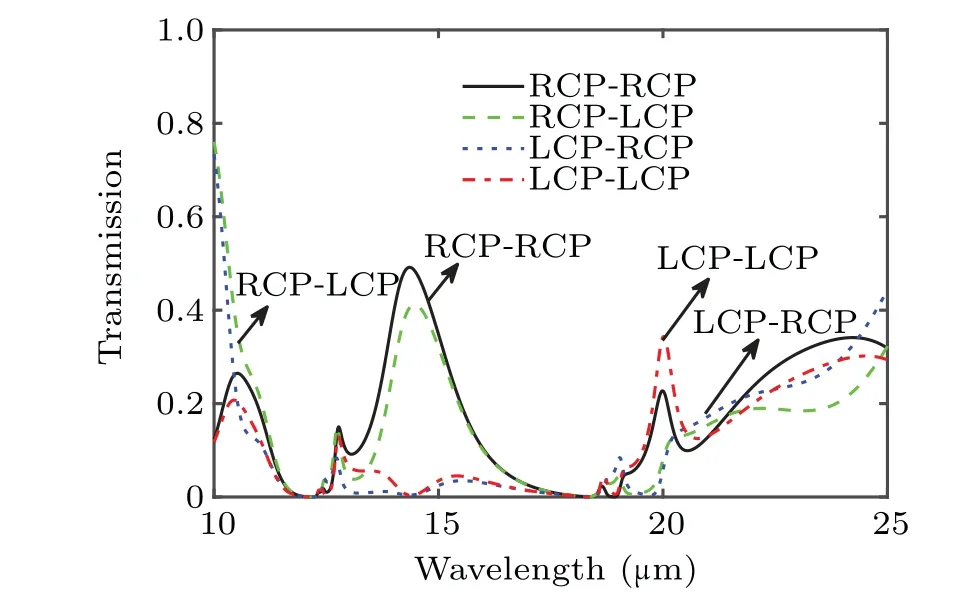
Fig.7. Components of LCP wave and RCP wave in transmitted wave.
To further explain the strong chirality of the bilayer structure, the components of TE wave and TM wave of the transmitted wave for normal incidence of an LCP wave and an RCP wave are shown in Figs.8(a) and 8(b). Here, the wavelength we concerned is still 14.4µm. It is found that the TM component in the transmitted wave is relatively small for an incident LCP wave, while the TM component can reach 0.9 for an incident RCP wave at the wavelength of 14.4 µm. Moreover,one can see that the TE component in the transmitted wave is almost zero for both the incident LCP wave and the incident RCP wave in a wavelength range from 11.8 µm to 18.3 µm.According to Ref. [49], the response of the structure for normal incidence of the TE wave and the TM wave are related toεyandεx, respectively. Since the sign of the real part of theεyis negative in the wavelength range of 11.8 µm-18.3 µm,now theα-MoO3behaves like metal,resulting in a strong reflection for TE wave. Thus, the anisotropic properties of theα-MoO3guarantee the giant chirality of the bilayer structure.
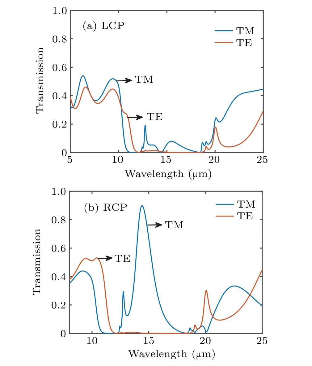
Fig. 8. Components of TE wave and TM wave in transmitted waves: (a)LCP wave and(b)RCP wave.
Here,the influence of the relative rotation angle on CD is discussed in the same situation as that in Fig.6,and displayed in Fig. 9. As the relative rotation angle increases, the CD slowly rises from 0 to the maximum value 0.89, and then decreases to nearly zero when the relative rotation angle is close to 90°. It is worth noting that the structure can still maintain strong CD over 0.8 when the relative rotation angle approximately ranges from 69°to 80°. Therefore,the CD is not very sensitive to the relative rotation angle, which reduces the requirement for angle in fabrication.
In fact, the influence of incident angle on the chirality is of vital importance. Thus, it is necessary to keep strong circular dichroism even at a large incident angle. Based on the optimized results as shown in Fig. 10, we discuss the transmissivity and CD varying with incident angle. When the incident angle increases from 0°to 90°, the transmissivity for LCP wave always keeps a low level while the transmissivity for RCP wave first maintains a large value and then decreases.It can be seen from the green line in Fig.10 that the CD can be larger than 0.85 when the incident angle is smaller than 40°,indicating that the chirality of the structure is robust against the incident angle.
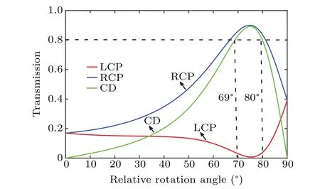
Fig.9. Curves of transmissivity versus relative rotation angle for LCP wave for LCP wave(red line), RCP wave(blue line), and the corresponding CD(green line), with bottom slab and top slab being 0.6 µm and 2.72 µm in thickness,respectively.
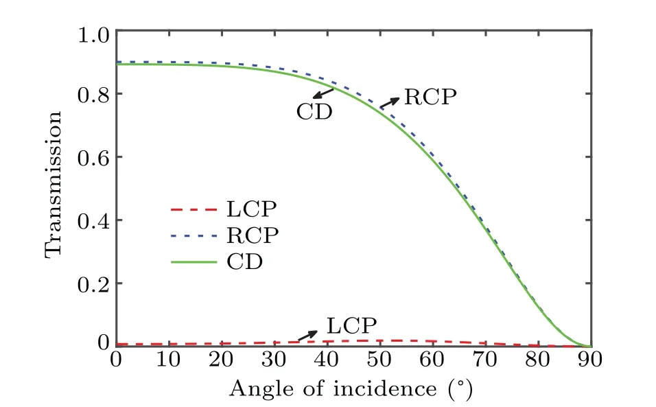
Fig. 10. Curve of transmissivity versus incident angle for LCP wave (red line), RCP wave (blue line), and the corresponding CD (green line), with wavelength being 14.4 µm, and bottom slab and top slabs 0.6 µm and 2.72µm in thickness,respectively.
4. Conclusions
In summary,a chiral structure based on twisted bilayerα-MoO3has been proposed and investigated. Through the optimization of parameters,the circular dichroism of the structure can reach 0.89. To reveal more in-depth physical mechanism,we analyze the polarization conversion between LCP wave and RCP wave. Furthermore,we discuss the influence of the relative rotation angle and the angle of incidence on the CD.The results show that the CD can keep a high level (CD>0.8)when the relative rotation angle approximately ranges from 69°to 80°. Besides,the CD is robust against the incident angle. It is believed that this work not only provides a new idea for chiral structure,but also promotes the development of the manipulation of circularly polarized wave.
Acknowledgements
Project supported by the Training Program of the Major Research Plan of the National Natural Science Foundation of China (Grant No. 92052106), the National Natural Science Foundation of China (Grant Nos. 61771385 and 52106099),the Science Foundation for Distinguished Young Scholars of Shaanxi Province, China (Grant No. 2020JC-42), the Science and Technology on Solid-State Laser Laboratory, China(Grant No.6142404190301),the Science and Technology Research Plan of Xi’an City, China (Grant No. GXYD14.26),the Shandong Provincial Natural Science Foundation, China(Grant No. ZR2020LLZ004), and the Start-Up Funding of Guangdong Polytechnic Normal University, China (Gtrant No.2021SDKYA033).
猜你喜欢
Chinese Physics B(2022年8期)2022-08-31
应用数学(2022年3期)2022-07-07
——浅谈新高考一轮复习备考策略
教学考试(高考数学)(2020年6期)2020-11-21
北方音乐(2019年10期)2019-07-10
北方音乐(2019年10期)2019-07-10
海峡姐妹(2019年3期)2019-06-18
岷峨诗稿(2016年3期)2016-11-26
民间故事选刊·上(2016年8期)2016-08-17
小小说月刊·下半月(2015年11期)2015-05-14
棋艺(2014年1期)2014-05-20

- Chinese Physics B的其它文章
- Quantum walk search algorithm for multi-objective searching with iteration auto-controlling on hypercube
- Protecting geometric quantum discord via partially collapsing measurements of two qubits in multiple bosonic reservoirs
- Manipulating vortices in F =2 Bose-Einstein condensates through magnetic field and spin-orbit coupling
- Beating standard quantum limit via two-axis magnetic susceptibility measurement
- Neural-mechanism-driven image block encryption algorithm incorporating a hyperchaotic system and cloud model
- Anti-function solution of uniaxial anisotropic Stoner-Wohlfarth model