
Smith-Purcell radiation improved by multi-grating structure
2022-04-12 03:46JingShu舒靖PingZhang张平ManLiang梁满ShengPengYang杨生鹏ShaoMengWang王少萌andYuBinGong宫玉彬
Chinese Physics B 2022年4期
关键词:张平
Jing Shu(舒靖), Ping Zhang(张平), Man Liang(梁满), Sheng-Peng Yang(杨生鹏),Shao-Meng Wang(王少萌), and Yu-Bin Gong(宫玉彬)
School of Electronic Science and Engineering,University of Electronic Science and Technology of China,Chengdu 610054,China
Keywords: Smith-Purcell radiation,multi-grating,resonance mode
1. Introduction
Modern nanofabrication techniques have promoted the development of photonics greatly and have brought new opportunities for fundamental effects study involving the interactions among free electrons, matter and light.[1,2]The interaction between an electron and photonic crystal structure gives rise to transient induced charges and currents that result in the emission of Smith-Purcell radiation (SPR).[3,4]The SPR is a wide spectrum electromagnetic radiation,[5,6]which has been obtained from the metal chains,[7]sub-wavelength hole array,[8,9]metamaterials[10-12]and photonic crystal,[13-18]etc.The physical mechanisms of superradiate SPR,[19,20]surface plasmon enhanced SPR[8-10]and compression SPR[8]have been found and analyzed by researchers.
From the view of image charge,the SPR radiation mechanism can be explained as below. When the electron beam is moving above the grating, the image charges are induced.If the grating groove and tooth change periodically, the distance between the electron and its image charge has a periodical variation like a dipole oscillation,then it emits radiation.
Recently, the SPR in photonic crystal attracted many interests, and an important reason is that there are still some novel physical phenomena and mechanism unclear or undiscovered in photonic crystal for SPR.Ochiaiet al. and Hoanget al.showed that the SPR could be realized by using the quasi-guided modes in the photonic crystal slab[13]and the planar defect mode of the woodpile photonic crystal.[18]The radiation is due to the coupling of a free electron and the electromagnetic modes of the photonic crystal,or the coupling between the electron and defect mode in the band gap. In addition,Zenget al. reported that more intensive scatter fields can be obtained in the photonic time crystals.[21]
Compared with the dielectric photonic crystal,[22]the metal photonic crystal will support stronger dipole oscillations and have stronger resonances. In this paper,we show that the improved SPR happens in a metal photonic crystal consisted of multi-grating structure,as shown in Fig.1.This structure leads to two advantages:(1)The radiation intensity is improved due to the increase of induced image charges,and(2)the spectrum distribution is improved due to the resonance characteristics.By optimization, the coherent directional THz radiation can be realized.
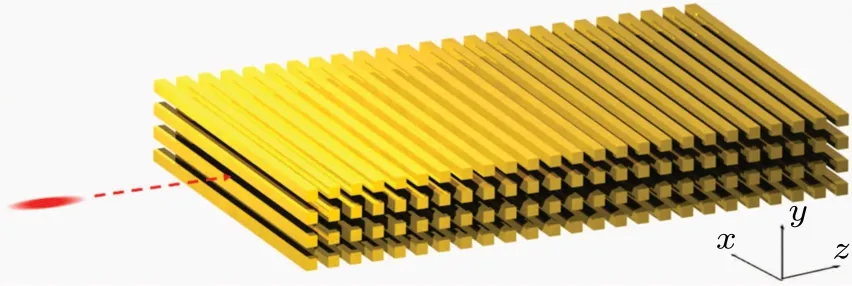
Fig.1. The schematic diagram of the multi-grating structure. When an electron bunch passed through this structure,the SPR emitted.The SPR is enhanced and has an obvious frequency peak.
2. Method
Precise understanding of the radiation excited by free moving electrons requires, in general, recourse to numerical simulations. The electrons behavior as well as the emitted radiation is well investigated by using the particle-in-cell(PIC)numerical method. Its processes involve interaction between the electrons and electromagnetic fields. Beginning from a specified initial state,the method simulates a physical process as it evolves in time. This approach provides self-consistency and is applicable to broad classes of free electron radiation problems.
In Fig.2,our metallic structure is set in the center of the simulation box. The radiation is calculated in three dimensions. The boundary of the simulation box is open (the electromagnetic fields are absorbed without reflection).It is equivalent to placing our structure in an infinite space and observing the radiation field in free space. We use a Gaussian shape line electron bunch with beam velocity 0.65c(cis the light velocity in vacuum),and place it at the left side of the box.[23]The length and charge quantity of the electron bunch is 160µm and 1×10-17C,respectively. In order to facilitate the analysis of the radiation field, the electromagnetic fields as functions of space or time variables are recorded.
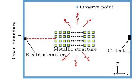
Fig.2. The PIC simulation model to calculate the SPR.
In order to analyze the phenomenon that the increasement of the radiation intensity due to more dipole oscillations occurring at the same time,we carry out researches on the radiations of one-row grating, double-row grating, and four-row grating structure. In addition, when the number of rows of grating increases, a strong resonance effect will happen in the multigrating structure. We study the resonance frequencies and resonance modes by plane wave excitation method,and verify the phenomenon that the resonance effect regulates the radiation frequency peak.
3. Results
3.1. Radiation from the one-row grating structure
Figure 3 is a schematic diagram of a one-row grating structure.It is composed by periodic metal pillars placed along thezdirection. The side lengthsaandbof the metal pillars are both 100µm,and the perioddin thezdirection is 200µm.The free electrons move above the metal grating along thezdirection,and the SPR will be excited.
The radiation mechanism of the SPR in a one-row grating structure is shown in Fig.3(c). When an electron moves to the top of the metal pillar,an image charge will be induced in the metal pillar. When the electron moves to the gap between two metal cylinders, an image charge will be induced at infinity.With periodic changes of metal pillar and gap, the free electrons and their corresponding image charges oscillate in the form of dipoles,and then the electromagnetic fields generate.
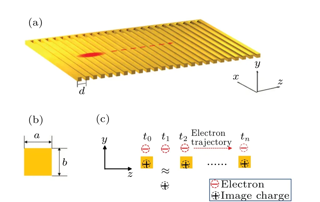
Fig. 3. (a) The schematic diagram of a one-row grating, d =200 µm.(b) Parameters of the cross section of the metal pillar, a=100 µm,b=100 µm. (c) Radiation mechanism of the SPR in a one-row grating. When an electron is moving above the grating, the image charge is induced. The grating tooth and gap change periodically,the distance between the electron and its image charge has a periodical variation like a dipole oscillation,then it emits radiation.
The time domain waveform of the radiation field at the position of 2000µm distance away from the grating surface is shown in Fig.4(b). From the time domain of the probe signal,the higher frequency part arrives at the probe first,and then the lower frequency part arrives. The contour map of the electric fieldEzat 20 ps is given in Fig.4(a),where red represents the positive electric field strength,and blue represents the negative electric field strength. For the convenience of comparison,the following simulation results will use the same scale.
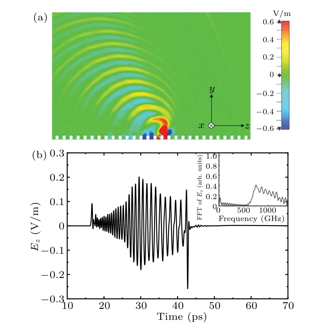
Fig.4. (a)The contour map of the electric field Ez at the time of 20 ps.(b) Time domain waveform of the electric field in a one-row grating structure. The inset is the spectrum of the radiation from one-row grating structure.
3.2. Radiation from the double-row grating structure
The radiation intensity of Smith-Purcell radiation decreases as the grating size decreases,so the radiation of a onerow grating structure is weak in THz. To achieve the purpose of enhancing radiation,the double-row grating structure is proposed as shown in Fig. 5. The distance between the gratings inydirection is 100µm. The free electrons move between the two rows of gratings at a constant speed along thezdirection to generate SPR.
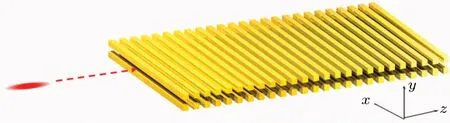
Fig.5. The schematic diagram of a double-row grating structure,where the distance between the gratings is 100µm.
Figure 6 shows the time domain waveform of the radiation field in the double-row grating structure. Compared with the one-row grating structure, the time domain waveform of the double-row grating structure is steeper,and the wave crest connection is smooth.It has a similar radiation frequency band with the one-row grating structure,but the field intensity is enhanced. The contour map of the electric fieldEzin the doublerow grating structure is given in Fig.6(a). It can be obviously noticed that the field of radiation from the double-row grating is stronger than that from the one-row grating structure.
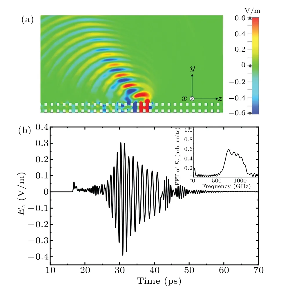
Fig.6. (a)The contour map of Ez. (b)Time domain waveform diagram of the electric field in a double-row grating structure. The inset is the spectrum of the radiation from double-row grating structure.
3.3. Radiation from the multi-grating structure
Since the double-row grating structure can induce more image charges to achieve the purpose of enhancing radiation,we subsequently suppose that the multi-grating structure could obtain stronger radiation than the double-row grating structure.Figure 1 gives the schematic diagram of the multi-grating structure which consists of four gratings.In this structure,four gratings are periodically arranged along theydirection with a period ofl=200µm. Free electrons move at 0.65calong thezdirection.
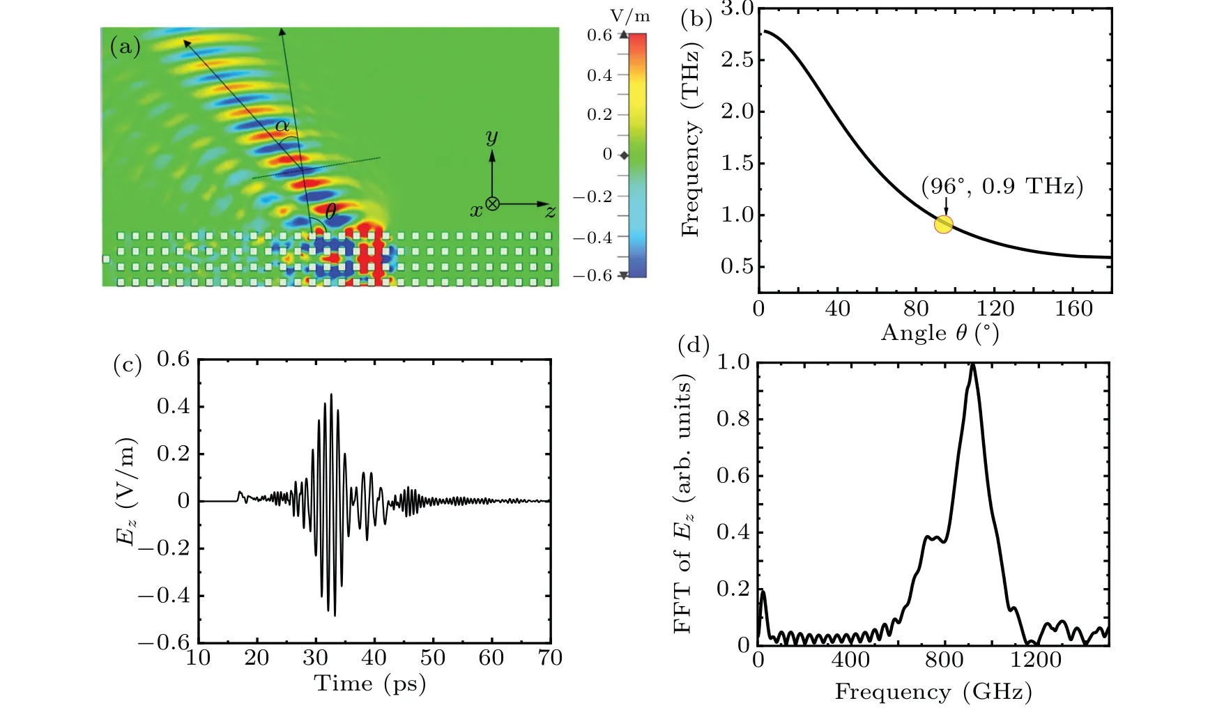
Fig.7. (a)The contour map of Ez in a multi-grating structure. (b)The relation between the radiation frequency and the radiation angle. (c)The time domain waveform of the radiation field in a multi-grating structure. (d)The corresponding spectrum of the radiation field.
The contour map of the electric field of radiation is given in Fig. 7(a). It can be seen that the radiation of the multigrating structure is the greatest among that of the one-row structure and that of the double-row structure grating. Observing the spatial distribution of the SPR in multi-grating structure from Fig. 7(a), the contrast between red and blue is sharp, indicating the radiation in the multi-grating structure has a strong intensity. There is a radiation direction in the contour map. It indicates that the radiation spectrum may has an obvious peak. In addition,there are two anglesθandαon the contour map. The angleθindicates the radiation angle when the radiation field spot just moves away from the grating surface. The angleαreflects the Doppler effect because of the movement of the electrons along the gratings. Based on the relation between the radiation frequency and radiation angle shown in Fig. 7(b), the radiation angleθ=96°corresponds to the frequency 0.9 THz. Figure 7(c) is the time domain of the radiation field,and its corresponding spectrum is given in Fig. 7(d). In Fig. 7(d), an obvious radiation frequency peak can be found,and it corresponds to the dot shown in Fig.7(b).
4. Discussion
The time domain waveforms of radiation field under different grating structures are shown in Fig.8. In order to facilitate the comparison, the observed probes are set at the same position for the three cases. It shows that the maximum values of the radiation fields for the one-row grating structure,double-row grating structure and four-row grating structure excited by the same electron bunch are 0.2 V/m,0.3 V/m and 0.45 V/m,respectively. With the increase of the row number,the radiation field intensity gradually increases.

Fig.8. The radiation fields for different grating structures.
Figure 9 are the spectrums of SPR for different grating structures. The spectrum has no obvious radiation peak in the one-row grating structure and the double-row grating structure, but the radiation of the double-row grating structure is stronger than that of the one-row grating structure. Compared with the one-row and double-row grating structures,the fourrow grating structure is prone to have a stronger resonance,its radiation spectrum becomes narrow, and a sharp radiation frequency peak appears.[24]
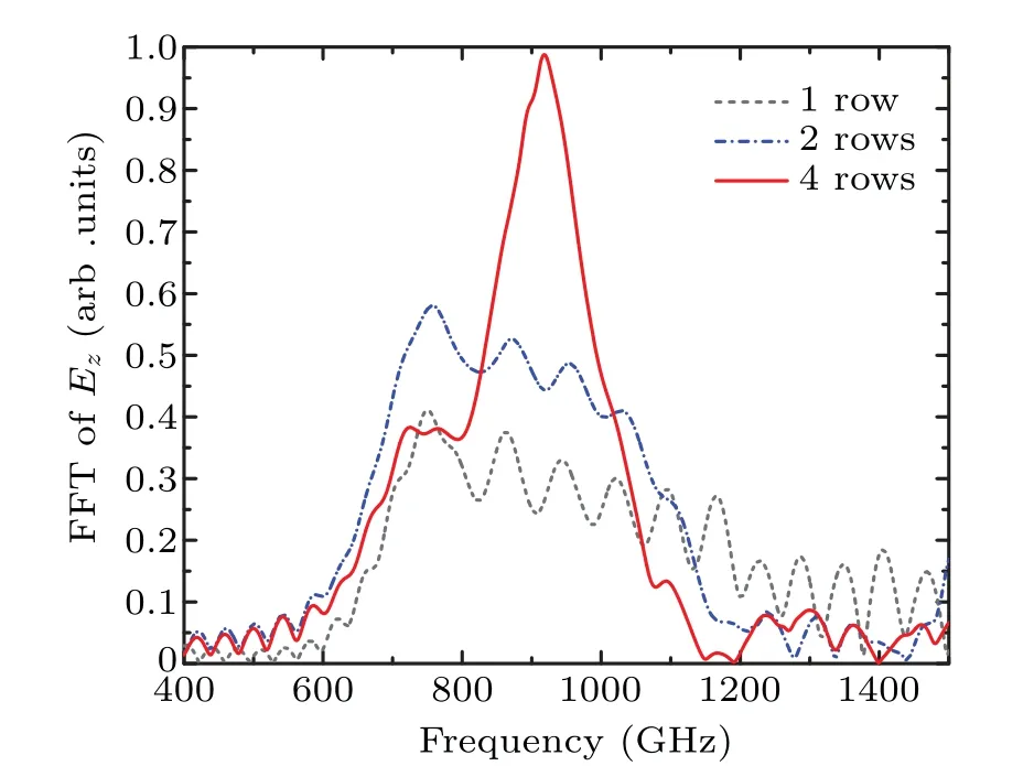
Fig. 9. The spectrum of the radiation for different grating structures.The black curve,red curve,and blue curve represent the SPR spectrum curves of a one-row grating structure, a double-row grating structure,and a four-row grating structure excited by the same electron bunch,respectively.
The increasement of the radiation intensity can be explained from the view of the dipole oscillations. When free electrons pass over the periodic metal structure, the image charges are induced, and the increase in the number of rows causes to more induced image charges. The radiation mechanism of the SPR in a double-row grating structure is shown in Fig. 10. Due to an extra row of grating, the more image charges are induced based on the complex image theory. For simplicity, only the two main mirror charges are considered here. It is the physical mechanism of the SPR enhancement in the double-row grating structure.[25,26]

Fig.10. Radiation mechanism of SPR in a double-row grating structure.
For the four-row grating structure, more dipole oscillations occur as shown in Fig.11.The increase of image charges results in increase of the number of dipole oscillations,which makes the intensity of SPR from the four-row grating stronger than that from the double-row grating structure.
In order to explain the generation of peak in the spectrum for four-row grating structure,we firstly give the Brillouin diagram of the radiation and the position of the peak,as shown in Fig. 12(a). The figure corresponds to the situation where electrons with a velocity of 0.65cpass over a structure with a period of 200µm. The electron beam line is expanded into harmonics in the periodical structure.The red line corresponds to the-1stspace harmonic of the electron. The gray shaded area shows the intersection of the electron line and the fast wave area, indicating the area corresponding to the radiation.The yellow point represents the position where the radiation frequency peak appears in the simulation, and it is located in the radiation region (the gray shaded area). In general, the appearance of this peak is closely related to the resonance in the four-row grating structure. It can be seen from Fig.12(b)that the structure has five resonance peaks,and the 0.907 THz resonance peak is located in the SPR radiation region. The resonance peaks below this frequency are all below the SPR radiation threshold and cannot be radiated. From the inset of Fig.12(b),it can be seen that the 0.907 THz resonance mode is symmetrical. In the electron channel,it has a strong longitudinal field and is easily excited by moving electrons. Comparing the curves shown in Fig.12(b),the resonance point ofS11is in good agreement with the peak of radiation spectrum.Through the change of the grating structure parameters, the resonance characteristics will be changed, and then the control of the grating resonant frequency can be realized.
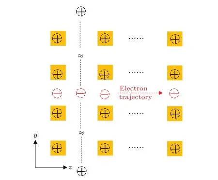
Fig.11. Radiation mechanism of SPR in a multi-grating structure.
Only the period of the structure is adjusted, and the PIC simulations andS-parameter simulations are carried out for the structure periods of 160 µm and 240 µm. TheS-parameters are shown as solid black lines in Fig. 13, and the resonant frequency varies with the period. The shaded areas represent the radiation spectrum of the structure under electron excitation, which also changes with the period. By comparing theS-parameter and the radiation spectrum,it can be seen that the corresponding relationship between the radiation frequency peak and the resonance point of the structure does not change.
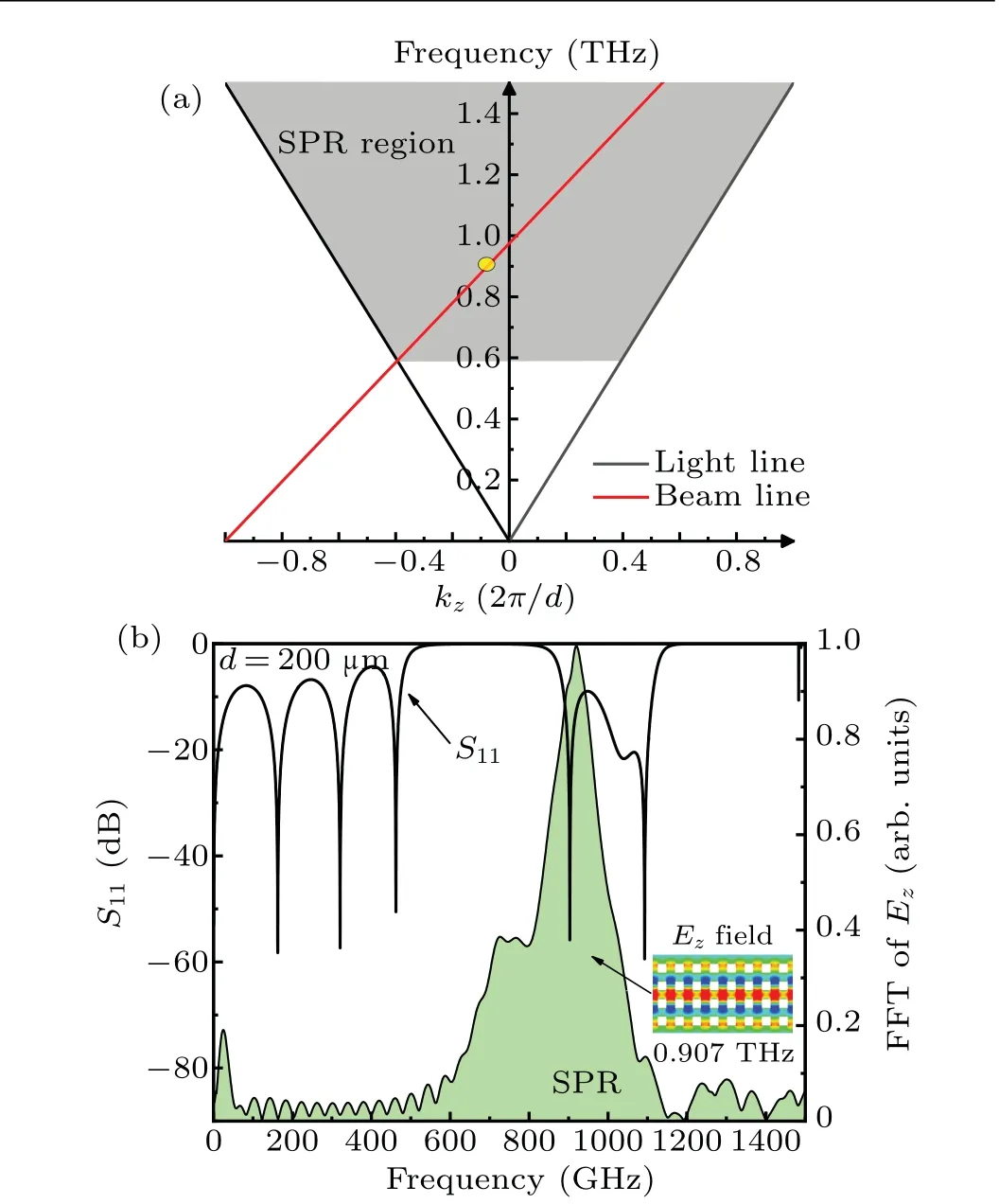
Fig.12. (a)The SPR diagram. The red line is the-1st harmonic of the electron beam with the velocity 0.65c. The gray area is for the SPR region. (b)The S11 curve and spectrum of the SPR.The inset figure is the Ez field distribution for the mode at 0.907 THz in the four-row grating structure.
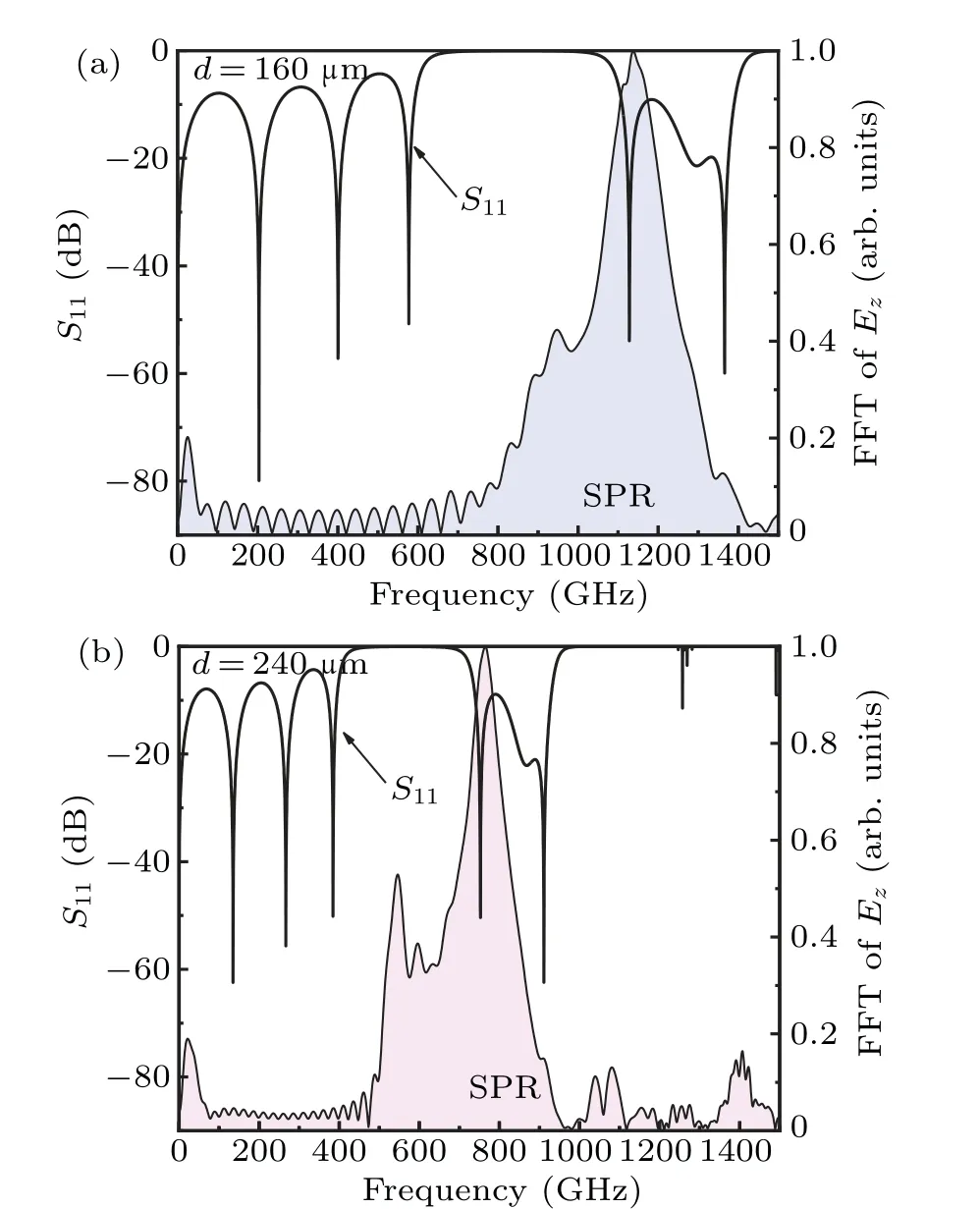
Fig.13. The S11 curve and spectrum of the SPR for(a)d=160µm and(b)d=240µm in the four-row grating structure.
We increase the width of the grating teeth(a)to reduce the gap between the grating teeth, so that the resonance effect of the structure can be enhanced. The radiation spectrums corresponding to differentaare shown in Fig.14. When the parameteraincreases, the intensity of the radiation frequency peak is greatly enhanced, while the frequency of the peak position is almost unchanged. The intensity of the radiation peak has a linear relationship witha,as shown on the left in the figure.Therefore,by enhancing the resonance effect of the structure,it is expected to obtain a stronger radiation frequency peak,and thereby a coherent SPR is obtained.
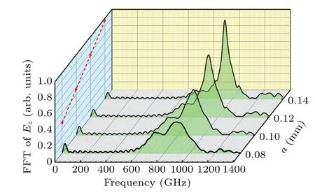
Fig.14. The spectrums of the radiation in a multi-grating structure for a=80µm,100µm,120µm and 140µm. The maximum values of the spectrums under different a are shown by the dots on the left face.
While the structural parameters remain unchanged, it means that the resonant frequency of the resonant mode does not change. We changed the frequency band range of SPR by changing the electron beam energy. When the electron velocity varies in the range of 0.55c-0.85c, although the range of SPR changes greatly, the resonant frequency of 0.907 THz is always located in the SPR region. Therefore,a radiation peak about 0.907 THz can be seen in the radiation spectrums of different electron velocities in Fig.15.
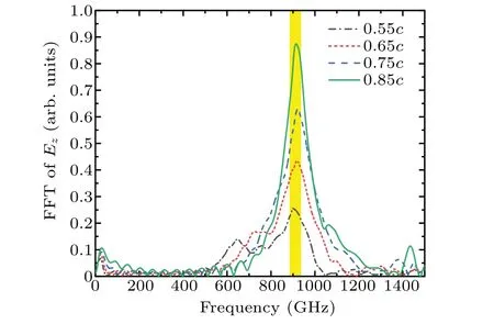
Fig.15. The spectrum of the SPR for 0.55c,0.65c,0.75c and 0.85c in the four-row grating structure.
5. Conclusion
In this paper, the physical phenomenon and mechanism of SPR in multi-grating are studied. The intensity enhancement of the radiation is explained by the occurrence of more dipole oscillations. The number of dipole oscillations of onerow, double-row, and multi-row grating structures gradually increases. And the radiation intensity obtained by the simulation is obviously gradually increased. The frequency tunability is considered to be caused by the resonance characteristics,and the multi-grating structure has a distinct radiation peak at the resonance point in the SPR radiation frequency domain. It will tailor the spectrum of the dipole oscillation energy.Therefore,the multi-grating structure not only offers more energy by increasing the image charges,but also tailors the SPR through the resonance characteristics. This mechanism is proposed to develop a method to improve the SPR,and it can be used for developing THz radiation source combined with micro-nano fabrication technology.
Acknowledgement
Project supported by the National Natural Science Foundation of China (Grant Nos. 61921002, 62171098, and 92163204).
猜你喜欢
装备环境工程(2022年7期)2022-08-10
雪豆月读·低年级(2021年12期)2021-12-23
金秋(2020年16期)2020-12-09
东坡赤壁诗词(2020年2期)2020-06-04
学校教育研究(2019年22期)2019-12-09
决策探索(2019年15期)2019-08-16
金秋(2019年2期)2019-04-16
微型小说选刊(2015年12期)2015-11-17
故事会(2013年2期)2013-01-09
故事会(2010年15期)2010-07-23

- Chinese Physics B的其它文章
- Quantum walk search algorithm for multi-objective searching with iteration auto-controlling on hypercube
- Protecting geometric quantum discord via partially collapsing measurements of two qubits in multiple bosonic reservoirs
- Manipulating vortices in F =2 Bose-Einstein condensates through magnetic field and spin-orbit coupling
- Beating standard quantum limit via two-axis magnetic susceptibility measurement
- Neural-mechanism-driven image block encryption algorithm incorporating a hyperchaotic system and cloud model
- Anti-function solution of uniaxial anisotropic Stoner-Wohlfarth model