
Low-overhead fault-tolerant error correction scheme based on quantum stabilizer codes
2022-04-12 03:48XiuBoChen陈秀波LiYunZhao赵立云GangXu徐刚XingBoPan潘兴博SiYiChen陈思怡ZhenWenCheng程振文andYiXianYang杨义先
Chinese Physics B 2022年4期
Xiu-Bo Chen(陈秀波) Li-Yun Zhao(赵立云) Gang Xu(徐刚) Xing-Bo Pan(潘兴博)Si-Yi Chen(陈思怡) Zhen-Wen Cheng(程振文) and Yi-Xian Yang(杨义先)
1Information Security Center,State Key Laboratory of Networking and Switching Technology,Beijing University of Posts and Telecommunications,Beijing 100876,China
2School of Information Science and Technology,North China University of Technology,Beijing 100144,China
3Advanced Cryptography and System Security Key Laboratory of Sichuan Province,Chengdu 610025,China
Keywords: fault-tolerant error correction,quantum stabilizer code,gate fault,quantum circuit
1. Introduction
Since quantum information is affected by noise during channel transmission, a technique is needed that can correct the noise in the channel and ensure the correct transmission of the information. Shor[1]first proposed that errors in quantum information can be correctly corrected by a quantum error-correcting code (QECC). At the same time, he designed the code [[9,1,3]], which requires nine qubits to encode a logical qubit and corrects any single-qubit error. Subsequently,through the classical error correction code,Calderbank, Shor, and Steane[2,3]proposed a new QECC scheme CSS (Calderbank-Shor-Steane) code, such as [[7,1,3]] code.However, the decoding process of CSS code is inefficient,since it cannot obtain the results of phase error and bit error in one step of measurement. Gottesman and Calderbank[2,4]proposed stabilizer formalism and formed a theory of stabilizer code to assemble a more available and further efficient quantum error correction code. The minor stabilizer code currently in existence is [[5,1,3]] code,[5]which can correct any single-qubit error using only five qubits. However,the abovementioned error correction codes can correct errors based on the condition that the error detection and error recovery operations can be performed entirely correctly without other errors.Detecting measurements and error recovery operations are complex quantum computations,and the hardware involved in the quantum computing process may be defective. Therefore errors may be introduced into the quantum information when the hardware fails.
A relatively straightforward route to achieving reliable computing is reducing the basic error rate of hardware during computing. However,a quantum system’s basic error rate is determined by the quantum computer hardware’s manufacturing quality and technical level,the interaction between the system and the environment,and the physical means of operation. Extraordinary experimental efforts in recent years have reduced the effect of the fundamental error rate on quantum systems in Refs.[6-9]. Using a QECC,Chouet al.[10]made the fidelity of teleported gate achieve 79%. Teleported gates have implications for fault-tolerant quantum computation. In addition to QECC, entanglement-assisted quantum error correction codes (EAQECC) have also been further investigated in Refs. [11,12], which improve the error correction capability of QECC.Then Joneset al.[13]asserted that a logical qubit must have four characteristics to be extensible, in addition to the DiVincenzo criteria for a quantum computer. Implementing a QECC scheme not only demands reducing the basic error rate but also should be fault-tolerant.
The superiority of QECC in fault-tolerant quantum computing was first introduced in Ref. [14]. It allows the correct quantum information to be recovered even if some errors occur during error detection and error recovery. Besides detection, the beginning application of QECC lies in protecting quantum information while performing calculations dynamically and in completing efficient quantum state transmission,[15,16]even by adopting defective logic gates during computation.Three representative FTEC schemes were introduced by Shor,[17]Steane[18]and Knill.[19,20]Salaset al.[21]made improvements such as“step”optimization,significantly reducing fault-tolerant syndrome extraction time and resource consumption. These methods have accomplished the control of the spreading error of the syndrome extraction circuit. Nevertheless, to achieve fault-tolerant syndrome extraction, it is essential to determine whether the syndrome qubits have introduced errors during the preparation process since otherwise,the errors could be propagated to the coding block.
Until 2017, Yoder and Kim[22]first proposed extracting fault-tolerant syndrome using flag qubits, which greatly reduced the consumption of ancillary qubits resources. After that,Chaoet al.[23-27]further introduced the“flag paradigm”,which works well for catching the correlated errors caused by quantum gate failures. Only two ancillary qubits are needed for various distance-three codes and≤d+1 ancillary qubits for any distance-dstabilizer code. Shortly after, the flag paradigm has been given for several code families: Hamming codes,[23]rotated surface and Reed-Muller codes,[28]color codes,[28-32]cyclic CSS codes,[33,34]heavy-hexagon code and heavy-square code.[35]In addition to the above mentioned abundant quantum codes, the flag paradigm can also be instrumental in preparing specific quantum states,such as magic state.[36,37]
Concerning the problem of two distinct sources of errors,noisy channels and defective hardware, ancillary qubits are added to distinguish between the two sources of errors. In actuality,the ancillary qubits overhead can complicate the device and make it difficult to operate. Therefore,this paper proposes a low-overhead FTEC scheme for quantum stabilizer codes by applying the flag paradigm to the syndrome extraction circuit.In this scheme,the Bell state is used as syndrome ancillas for measuring the coding block to achieve error correction performance; in contrast, flags are added to verify the CNOT gate and perform error tolerance performance. This scheme reduces the overhead of ancillary qubits and the overhead of circuit depth,and the probability of storage errors occurring.
Following the introduction,Section 2 begins with the review of the action the error propagation through the CNOT gate. Then Section 3 concentrates on our FTEC scheme in error detection and fault detection. We take Hamming code[5,1,3] as an example to describe our fault-tolerance scheme in Section 4. The conclusion of this paper is given in Section 5,and analytical results are presented to demonstrate the fault-tolerant performance of the proposed FTEC scheme.
2. Preliminaries
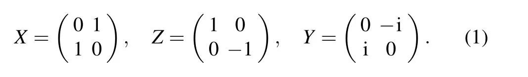
In quantum information,the quantum state is a vector in(C2)⊗n, and the error is a unitary linear transformation. According to the simplified model of Shor and Steane,any single quantum state error can be expressed as a combination of theX,Y,andZerrors. We only need to consider the three typical errors,X,Y,Z,where
A stabilizer code is a common eigenspace of a set of commuting products of Pauli operators. A generator in stabilizer may beX-type (consisting of only PauliXandIoperators)operator,Z-type(only PauliZandI)operator, or mixed-type(any other combination of Pauli operators).
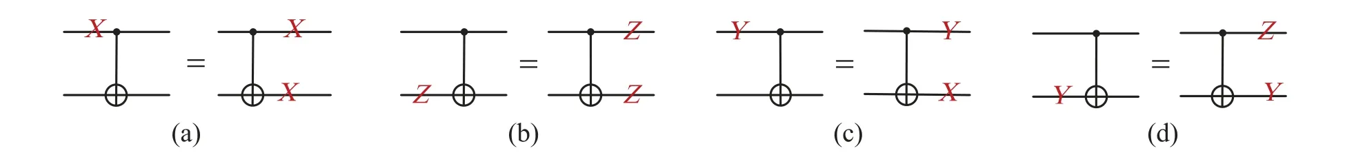
Fig.1.(a)An X error can be propagated from the control qubit into the target qubit through the CNOT gate.(b)On the contrary,a Z error propagates from the target to the control qubit. (c)and(d)At the same time,a Y error will evolve into an X or Z error.
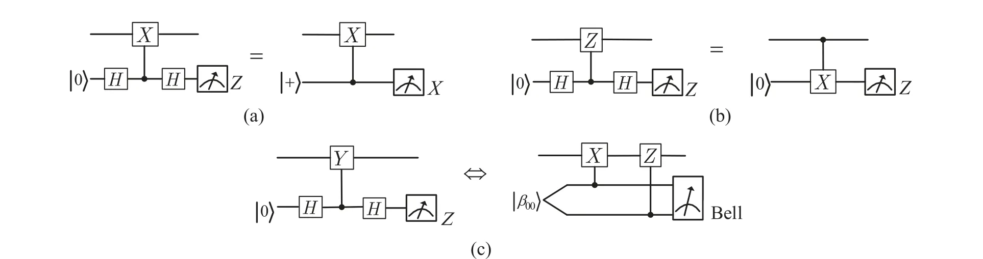
Fig.2. The circuits of measurement of the Pauli X,Z and Y operators. (a)The circuit on the left of the equal sign uses the Z-basis to measurement,and the right uses the X-basis(|+〉,|-〉). (b)The equivalent circuit of CNOT gate and control-Z gate, finally measured with the Z-basis(|0〉,|1〉).(c)A control-Y gate can be divided into CNOT gate and control-Z gate provided that the global phase factor is ignored.The symbol“Bell”indicates a Bell basis(as in Eq.(2))measurement. Provided an X or a Z error in the data,the measurement result will be|β10〉. While a Y error occurs,|β00〉will be given.
A general error of a single qubit can be expressed as a sum of Pauli operators taken from the setP={I,X,Z,Y= iXZ},whereIis the identity(corresponding to no error). Errors can be propagated between the target and the control qubits of a CNOT gate in Fig.1.
Using the error transmission nature of CNOT gates to implement parity checking of a stabilizer code, extract the syndromes,locate the error type and error location,and complete error detection and correction. The error syndrome extraction is a critical step in errors detection and errors correction. The equivalent circuits of the CNOT, control-Zand control-Yare shown in Fig.2.
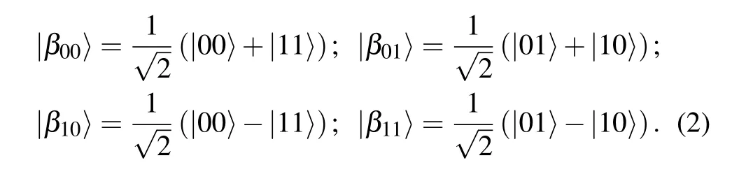
The four Bell states are
The error transmission nature of the CNOT gate raises the possibility of error propagation, allowing severe errors to occur in the coding block, exceeding the error correction capability of the error correction code itself and producing a permanent error code. Therefore the syndrome extraction circuit needs to be fault-tolerant.
3. Flag-FTEC scheme
A delicately designed circuit can not only correct errors introduced in the noisy channel but also tolerate faults by itself. The difference between fault and error is as follows:[38]Fault is a location in a circuit where a gate or storage error occurs while error is associated with a qudit in a block that deviates from the ideal state. Fault happens at fixed points in the circuit but error may happen when the qudit is in fly. The circuit is referred to as a fault-tolerant circuit, i.e., the faults produced and propagated by the quantum gates in such a circuit are correctable. Next, we will introduce a low-overhead FTEC scheme, which not only reduces the error propagation path but also corrects the correlated errors on data.
3.1. Error detection-split each stabilizer generator into X-type and Z-type for classification measurement
When Alice sends an encoded quantum state|φ〉to Bob through a noisy channel, the encoded quantum state|φ〉is transformed into a noisy data|φ〉=ε|φ〉, whereεis a channel noise operator. In order to correct the errorε, Bob starts to prepare Bell states|β00〉as syndrome qubits and uses all stabilizer generators to measure|φ〉. Each stabilizer generator is divided intoX-type andZ-type operators. The termX-type(orZ-type) operator includesX(orZ) operator only. A stabilizer generatorg=XZZXI=X14Z23I5illustrates this point clearly. Let lettersA,B,andCdenote,respectively,the set of subscripts of Pauli operatorsX,ZandI,then the stabilizer generatorg=XZZXI=X14Z23I5can be depicted asg=XAZBIC(usually denoted asg=XAZB). The circuit of extracting generatorg=XAZBsyndrome is illustrated in Fig.3.In particular,if there is noYPauli operator in the generator,A ∩B= /0 andA∩B/= /0 otherwise.
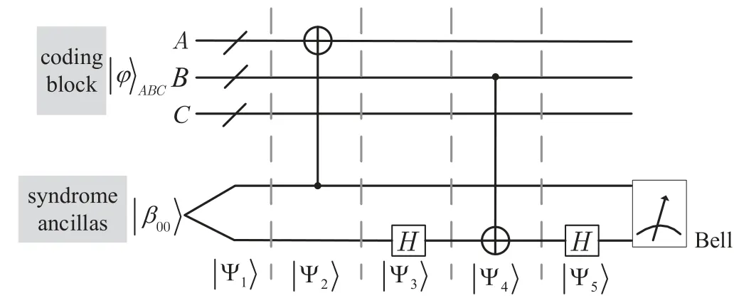
Fig.3. Diagram for a syndrome extraction circuit that detects channel noise.A noisy data is ε|φ〉=|φ〉ABC and syndrome ancillas are|β00〉. Time moves from left to right,with wires used to represent the passage of time where the states are single or multiple. |Ψ1〉, |Ψ2〉, |Ψ3〉, |Ψ4〉, |Ψ5〉are evolution of all quantum states.
According to Fig.3,the quantum states|Ψ1〉,|Ψ2〉,|Ψ3〉,|Ψ4〉,|Ψ5〉can be achieved followed by the operation of the circuit goes as follows,with the steps applied in order:
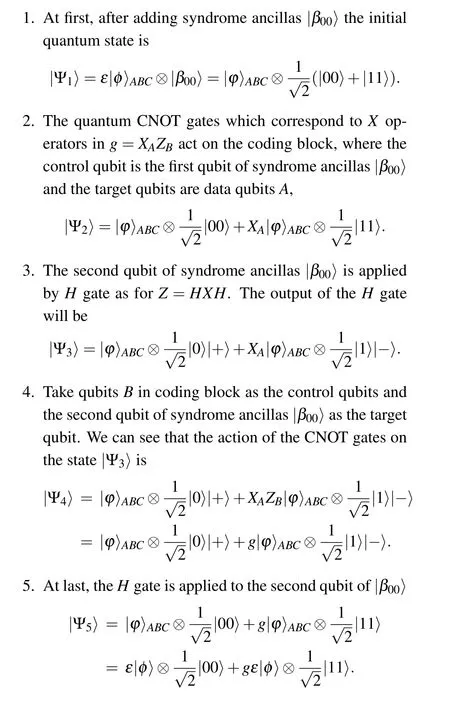
Through the above error detection process, we can find that it also works when the syndrome ancillas here is initialized into|β10〉. Conversely, when the syndrome ancillas collapses into|β00〉,then the noise operator must exist and satisfygε=-εg.
It can be viewed from the above quantum circuit that the final syndrome ancillas measurement not only did not cause the collapse of the qubits in the coding block (data) but also copied the error in the coding block to the syndrome ancillas.Subsequently, this circuit diagram can be invoked as the circuit of syndrome extraction for data. LetS=(s1,...,sr)∈Fr2denote error syndrome of all stabilizer generatorsg1,...,gr.Prepare syndrome ancillas in|β00〉to measure theith generator followed by measuring with Bell base. If the result is|β00〉(|β10〉), then the corresponding elementsi=0 (si=1). We can find that it also works when the syndrome ancillas here is initialized into|β10〉. Conversely, when syndrome ancillas collapses into|β00〉,the noise operatorεmust exist and satisfygε=-εg.
Above measurements must also be fault tolerant. If not,error accumulation would rapidly destroy the coherence of the states in the computer.
3.2. Fault detection - flag particles |0〉 and |+〉 are used to detect X and Z faults simultaneously
In the following subsection,we will put forward a procedure based on adding“flags”qubits to catch the quantum gate faults that can lead to correlated errors on coding block.
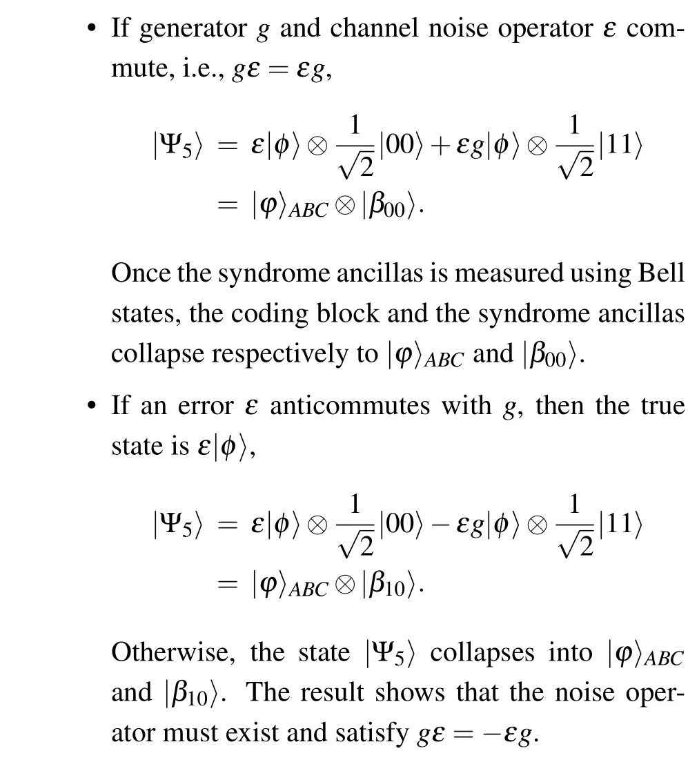
At first, syndrome ancillas|β00〉are equipped with two flags ancillas|0〉and|+〉with the view to increasing faulttolerance performance as in Fig. 4. The syndrome ancillas detects errors in the coding block,and the two flags qubits can be used as a verification block. The verification block is significantly different from Shor state[17]and Steane state[18]in an essential respect that the verification block herein is not to verify whether the syndrome ancillas is prepared correctly,but to catch the faults that can lead to correlated errors on the data.
Fig.4. Fault detection. (a)If an X or Y error is introduced to the first qubit of|β00〉state,the Z-basis(|0〉,|1〉)measurement will always give|1〉. Otherwise,|0〉. (b)If a Z or Y error occurs,the X-basis(|+〉,|-〉)measurement will show|-〉;otherwise,|+〉.
Then extract syndrome for stabilizer generatorg=XAZBis shown in Fig.5. LetXAi(orYAi)denote as anXfault(or aYfault)which comes from theith CNOT gate corresponding to setAon the control qubit, wherei=1,2,...,|A|. And again,we can defineXBj(orYBj) as anXfault (or aYfault) which comes from thejth CNOT gate corresponding to setBon the target qubit, wherej=1,2,...,|B|. In fact, the CNOT gate corresponding to the setA(B)may also introduce faults in the target(control)qubit,but the faults are not propagated to other quantum bits and therefore do not cause error multiplication.
• If there is no channel noise error(the channel noise error may commute with the generatorg=XAZB)and no quantum gate fault, the measurement results are shown in column 2 of Table 1.
• If the coding block is only affected by channel noiseε, all measurements are shown in column 3 of Table 1 when the generatorg=XAZBanticommutes withε.
• If anXAiorYAifault is introduced,the following CNOT gates will propagate the fault inAto the coding block and flag-1,causing the weight of coding block error≥1 and the flag-1 raised.
- WhenA ∩B= /0, if anX(orY) fault occurs, the measurements of syndromes ancillas is|β01〉(or|β11〉).
- WhenA ∩B/= /0, based on the quantum circuits in Fig. 2, a control-Ygate in quantum circuit can be represented as shown in Fig. 6. If anX(orY)fault occurs,theXerror is propagated through the CNOT gate in the direction of the red arrow and the measurements of syndromes ancillas is|β11〉(or|β01〉).It is notable for its inability to distinguish between theXAiandYAifaults by the results of Bell measurements of syndrome qubits as shown in columns 4 and 6 of Table 1. Fortunately,theXandYfaults result in the same error in the coding block regardless of whether the intersection ofAandBis the empty set.
• If anXBjorYBjfault is introduced,the following CNOT gates will propagate the fault inBto the coding block and flag-2,causing the weight of coding block error≥1 and the flag-2 raised. TheXBjorYBjfault also can be identified by the results of Bell measurements of syndrome qubits. Therefore, the measurements ofXBjorYBjfault are shown in columns 5 and 7 of Table 1.
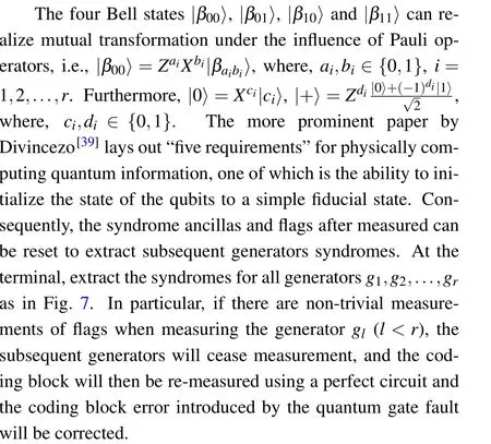
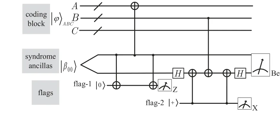
Fig.5. Flagged syndrome extraction for stabilizer generator g=XAZB.

Fig.7. The quantum measurement circuit to extract syndromes of all generators g1,g2,...,gr in turn. The syndrome ancillas and flags are respectively initialized to |β00〉, |0〉 and |+〉, then used to measure the generator g1.|βa1b1〉,|c1〉, are the quantum states after the measurement of g1. Output the measurement results a1,b1,c1,d1 and reset by Za1,Xb1,Zc1 and Xd1 operators for g2. Similarly,the measurement of generator gr is preceded by resetting |βar-1br-1〉,|cr-1〉, through Zar-1, Xbr-1,Zcr-1 and Xdr-1 operators.

Fig. 6. Propagation of an X or Y fault through two CNOT gates acting on the same qubit. The red arrow indicates the propagation path of an X error.

Table 1. The relationship between measurement results and CNOT gates faults.
Through the measurement results in Table 1,we can correct the errors as follows:
• If the coding block immunizes to the channel noise(or channel noiseεcommutes with all generatorsg1,g2,...,gr) and the CNOT gate introduces no-fault,the measurement results of all ancillary quits are trivial.Therefore,the syndromesS=(s1,...,sr)=0.
• If the coding block is affected only by the noise channel,the measurement results of party generators are presented in the third column,the remaining are in the second column,and the quantum syndrome isS/=0.Finish by applying the corresponding correction.
• If flags measurement outcomes remain non-trivial,it indicates that a single CNOT gate introduces a fault propagated to the coding block. By practising“flag”ancilla,the fault type(X,YorZ)and range(CNOT gate corresponding to setAorB)can be determined. Measure all generators with unflagged circuits (perfect) once again to figure out the position of the gate fault. If two coding block errors are affected by the failure of CNOT gates in the same setAorB, the coding block error can be corrected when the syndromes corresponding to these two errors are different.
Through the above analysis, we summarize the whole program by a flowchart as shown in Fig. 8. Using Fig. 7 to initialize the ancillary qubits, record the measurement results based on Table 1.
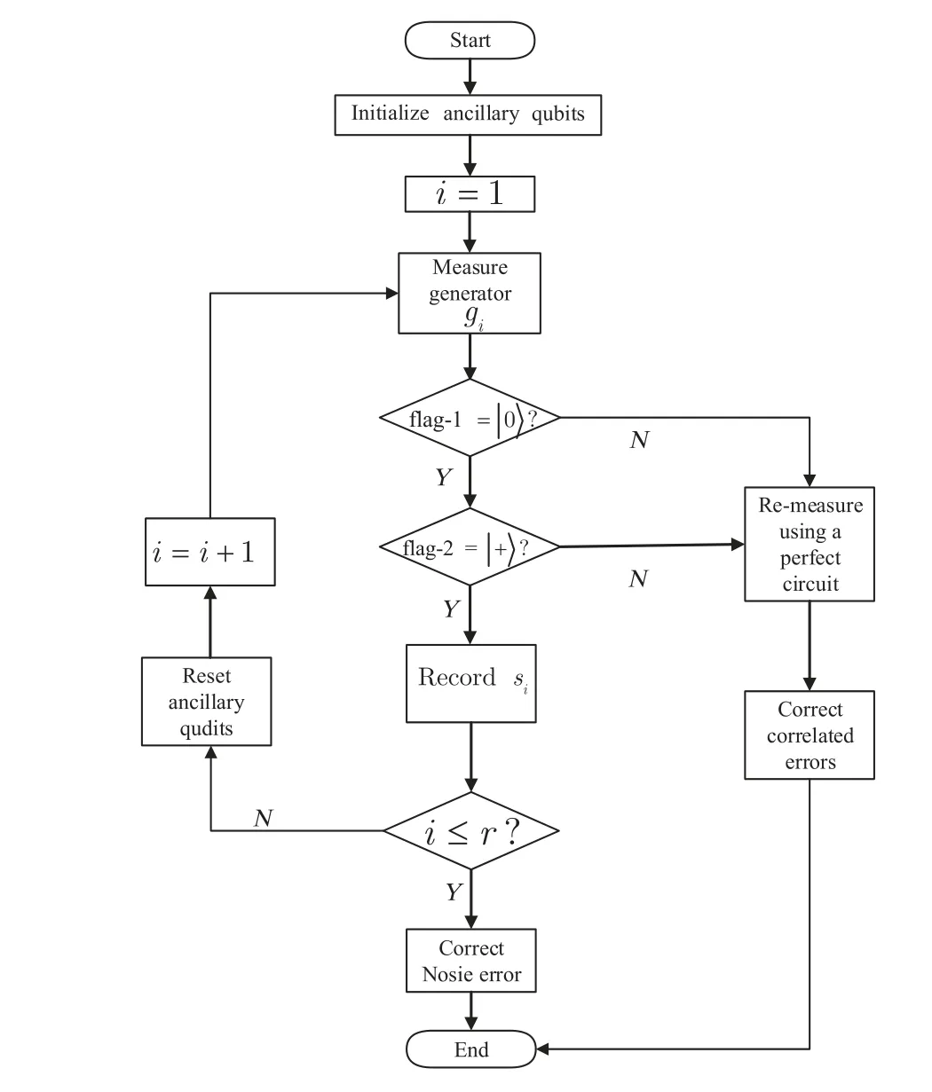
Fig. 8. A flowchart for summarizing the flag paradigm idea to realize the fault-tolerant error-correction.
Let us point out that,in our above scheme,multiple measurements are required to measure the reliability of the results,and the majority decision method is adopted to determine the ultimate result.
4. Fault-tolerance scheme for[[5,1,3]]code
The most insignificant error-correcting stabilizer code[[5,1,3]] can correct up to one error at any qubit[5]with stabilizer generatorsg1=XZZXI,g2=IXZZX,g3=XIXZZ,g4=ZXIXZ. Before the error-correction procedure, we assume that the data error weight is≤1.The syndrome ofg1can be extracted by the circuit in Fig. 9, presented by Ref. [23],where a flag can “catch” aZfault introduced by the CNOT gate. It allows one to examine the[[5,1,3]]code,single-error correcting stabilizer code, adopting two extra qubits barely.Were we to use the error-correction procedure in Fig. 9, although the quantum circuit reduces the cost of ancillary qubits,it increases the cost of circuit depth. For example, the circuit depth is 8 in Fig.9.Besides,theZfault will propagate through the subsequent gates and become anX-type fault. For example,provided that the gatecintroduces anIZfault,theIZfault will be propagated through the next gate,followed by becoming anIIIXIerror to the data.To resolve the problem of circuit depth overhead,we practice the circuit in Fig.9 to extract the syndrome forg1. The flag-1 (flag-2) ancilla can “catch” theX(Z) fault simultaneously. The principal criterion between Figs.9 and 10 lies in the syndrome ancillas and flag qubits,an essential part of fault-tolerance schemes. Figure 10 shows that the circuit depth for extracting the syndrome ofg1is 6,which is due to the fact thata,bandc,dcan run in parallel.

Fig.9. (a) Flagged syndrome extraction for g1 =XZZXI in [[5,1,3]]code put forward by Chao et al. (b) The equivalent circuit of a and d quantum gates in(a).
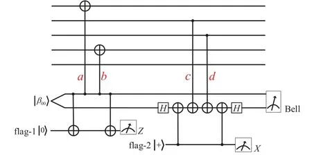
Fig.10. Flagged syndrome extraction for[[5,1,3]]code. The circuit to extract the syndrome of the stabilizer g1 =X14Z23 with |β00〉 state and two flag-qubits which are prepared in the |0〉 and |+〉 states. The symbols a,b (or c, d) stand for CNOT gate which correspond to sets A={1,4} (or B={2,3}),respectively. The syndrome ancillas and flags are measured at the end of the circuit by Bell basis,X-basis and Z-basis.
If the data has no errors then the Bell-basis,X-basis andZ-basis measurements will always give|β00〉,|0〉and|+〉,respectively.
If the CNOT gateaorbfails and introduces anX(orY)fault on control qibit, this fault will lead|β00〉and flag-1 ancilla to become|β01〉(or|β11〉)and|1〉. Here,the 1st and 4th qubits may be suffer from errors in Table 2, where the first(second)error operator stands for the CNOT gate fault on the control(target)qubit. Use unflagged circuits to extract all four syndromes ofg1,g2,g3,g4again. It is surprised to find that the syndromes of these errors are different. Therefore, when the flag-1 ancilla is raised, the correlated errors on data are correctable by applying the corresponding correction.
In the same way, if aZ(orY) fault stems from the controlled qubit ofcordgate the measurements will be|β10〉(or|β11〉),|0〉and|-〉. The data errors can be corrected perfectly according to data errors and syndromes in Table 2.
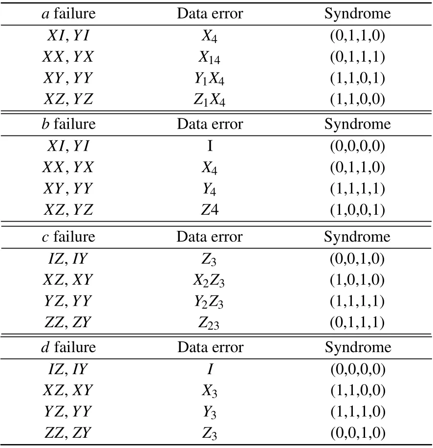
Table 2. The correlated errors and their corresponding syndromes.
Similarly, apply the flagged circuit to extractg2,g3,g4and followed by correcting errors based on the measurement of syndromes and flags.
5. Discussion
Both Shor’s[17]and Steane’s[18]FTEC schemes practice transverse fault-tolerant technology to prevent errors to cross propagation. A common feature of both schemes is the possibility of measuring all operators in a generator in parallel,but this is based on the overhead of the ancillary qubits. On the one hand, for an [[n,k,d]] CSS code, the ancillary qubits costs in the above Steane’s and Shor’s schemes are≥2(n+1)and≥2ω-1 (orω+1), respectively, whereωis the maximum weight of all stabilizer generators. On the other hand,the ancilla in Shor’s scheme is prepared in “cat state”, while the ancilla in Steane’s scheme is prepared in a superposition of all states satisfying the parity checks ofH,where each row ofHis interpreted as a single 2n-bit parity check. Consequently,their schemes require the preparation of syndrome ancillas into complex specific quantum states and increase circuit depth for the preparation of ancillary qubits. For example,if the Shor’s and Steane’s schemes are used on the[[5,1,3]]code,the circuit depths for preparing the syndrome ancillas are 5 and 6,respectively.If the verification fails,the syndrome ancillas need to be re-prepared,so the overhead in the circuit depth for preparing the syndrome ancillas is 5tand 6t',wheretandt'are the times of preparing the syndrome ancillas. Considering that the measurement generators can be parallelized,the total overheads of circuit depth areTcat>5tandTSteane>6t',respectively.
In the “flag” fault-tolerant scheme proposed by Chaoet al., only one syndrome qubit is used in the syndrome ancillas. Although the overhead of the ancillary qubits is reduced,it is at the cost of increasing the circuit depth. If measure the generatorg=XAZBin Chaoet al.’s scheme,the circuit depth overhead is max{|A|+|B|}(ignore the Hadamard gate). The merits of our scheme are reflected in [[5,1,3]] code as in Table 3.
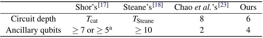
Table 3. The comparison of circuit depth between our scheme and Shor’s,Steane’s,Chao et al.’s schemes in[[5,1,3]].
In our scheme,the required ancillary qubits are independent of the weight and quantity of the stabilizer generator,and the ancillary states do not need to be verified as it is prepared correctly before deciding whether it can be used in the syndrome extraction circuit.Compared with Chaoet al.’s scheme,our scheme uses the Bell state as the syndrome ancillas. The advantages of the Bell state as the syndrome ancillas are apparent,which can reduce the circuit depth and the influence of memory errors on the coding block and reduce errors propagation path. Most importantly, the scheme can be applied to any general stabilizer code provided that the errors on data can be detectable and distinguishable. It is not difficult to find that our scheme is suitable for general stabilizer codes in addition to CSS codes.
Based on the above analysis,we can see that our scheme has the following characteristics:
• The overhead of the ancillary quantum state is only 4,which is independent of the number and weight of the stabilizer generators.
• With the application of Bell states as syndrome qubits,the overhead of circuit depth for generatorg=XAZBis reduced to max{|A|,|B|}.
• Ancillary states are simplistic to prepare and can be reused by various generators through resetting the ancillary states when to measure coding blocks.
• Our FTEC scheme is broadly practised and is not confined to CSS codes but can further be implemented to general quantum stabilizer codes.
Acknowledgements
Project supported by the National Natural Science Foundation of China (Grant Nos. 61671087 and 61962009),the Fundamental Research Funds for the Central Universities, China (Grant No. 2019XD-A02), Huawei Technologies Co. Ltd (Grant No. YBN2020085019), the Open Foundation of Guizhou Provincial Key Laboratory of Public Big Data(Grant No.2018BDKFJJ018).

- Chinese Physics B的其它文章
- Quantum walk search algorithm for multi-objective searching with iteration auto-controlling on hypercube
- Protecting geometric quantum discord via partially collapsing measurements of two qubits in multiple bosonic reservoirs
- Manipulating vortices in F =2 Bose-Einstein condensates through magnetic field and spin-orbit coupling
- Beating standard quantum limit via two-axis magnetic susceptibility measurement
- Neural-mechanism-driven image block encryption algorithm incorporating a hyperchaotic system and cloud model
- Anti-function solution of uniaxial anisotropic Stoner-Wohlfarth model