
Design of cylindrical conformal transmitted metasurface for orbital angular momentum vortex wave generation
2022-04-12 03:44BenFu付犇ShiXingYu余世星NaKou寇娜ZhaoDing丁召andZhengPingZhang张正平
Chinese Physics B 2022年4期
Ben Fu(付犇), Shi-Xing Yu(余世星), Na Kou(寇娜),Zhao Ding(丁召), and Zheng-Ping Zhang(张正平)
Key Laboratory of Micro-Nano-Electronics and Software Technology of Guizhou Province,College of Big Data and Information Engineering,Guizhou University,Guiyang 550025,China
Keywords: orbital angular momentum,cylindrical conformal transmitted metasurface
1. Introduction
With the rapid development of wireless communication technology, data transmission rates in areas such as big data and cloud computing are growing exponentially. It is a matter of the utmost urgency to improve capacity of wireless communication systems with limited spectrum resource. Vortex waves carrying orbital angular momentum (OAM) are expected to solve this issue.[1]It can simultaneously transmit multiple orthogonal modes in the same channel without increasing the bandwidth, which can provide an extra dimension for the information modulation.[2]OAM vortex waves are characterized by a wavefront phase factor as exp(ilφ),whereφis the azimuth angle, andlis the OAM mode number. Especially,the OAM mode numberlcan be arbitrary,and different modes are orthogonal to each other without interference.Therefore, using OAM modes for encoding and multiplexing can greatly improve spectrum utilization and increase channel capacity in optic domain and radio domain,[3,4]also enhance wireless data transmission rate and reduce the crosstalk in radio domain.[5]In addition, OAM vortex waves can be used to elevate target detection in radar applications and research has shown that OAM vortex waves can improve resolution of radar imaging.[6,7]Now,radio vortex waves have become a hot topic. How to efficiently generate OAM vortex waves is a key issue widely concerned by researchers.
OAM was originally studied in optics. Until 2007,Thid´eet al.introduced OAM from optics to radio frequency.[8]In 2012,the first experiment of OAM communication in radio domain was implemented successfully.[4]At present,researchers have proposed a variety of antennas for generating OAM waves, such as spiral phase plates,[9]spiral reflectors,[10]circular arrays,[11]traveling wave antennas,[12]dielectric resonant antennas,[13]and metasurfaces.[14-20]In particular,there are two types of metasurfaces: reflective metasurfaces[21]and transmitted metasurfaces.[22,23]Compared with reflective metasurfaces, transmitted metasurfaces can reduce blockage of feed antennae. Researchers have shown that transmitted metasurfaces can effectively generate OAM vortex waves.However, the generated OAM vortex waves are all in planar structures.
Recently, metasurfaces studies have gradually extended from the planar to the conformal.[24-29]Conformal transmitted metasurfaces can fit the shape of various installation platforms. Due to advantages of conformal transmitted metasurfaces, they have attracted great attention. A 3-bit doublelayer conformal transmitted metasurface with high aperture efficiency is reported for generating high gain waves.[30]However, the generation of OAM vortex waves with conformal transmitted metasurfaces has not yet been discussed. Therefore, in this paper we propose a design of cylindrical conformal transmitted metasurface for generation of OAM vortex waves. A theoretical formula of phase distribution to generate OAM vortex waves is derived with cylindrical conformal transmitted metasurfaces. A prototype of the cylindrical conformal transmitted metasurface is design, fabricated and measured. The OAM vortex wave is effectively generated by the conformal transmitted metasurface,which verifies the proposed theoretical formula and the feasibility of the conformal configuration.
2. Conformal transmitted metasurface design
Consider a cylindrical transmitted metasurface fed by a horn antenna to generate OAM waves, as shown in Fig. 1.Here,u0represents the propagation direction of the main wave,rmnis the position vector at themn-th unit cell, andrfrepresents the position vector of the feed horn.Φmnis the required phase shift value ofmn-th element on the transmitted metasurface,

wherelis the OAM mode number,k0is the wave number in free space,φmnis the azimuth angle ofmn-th unit cell,anddis the distance from themn-th element of the cylindrical transmitted metasurface to the reference plane. Equation(1)is the proposed formula to calculate the phase distributions of the cylindrical conformal transmitted metasurface for generation of OAM vortex waves.
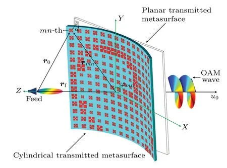
Fig.1. Geometry of the cylindrical conformal transmitted metasurface.
The unit cell of the transmitted metasurface is printed on a substrate with double-layer metal-clad fractal squares and four metal vias connecting the two metal layers,as shown in Fig.2.

Fig.2. The unit cell of the transmitted metasurface.
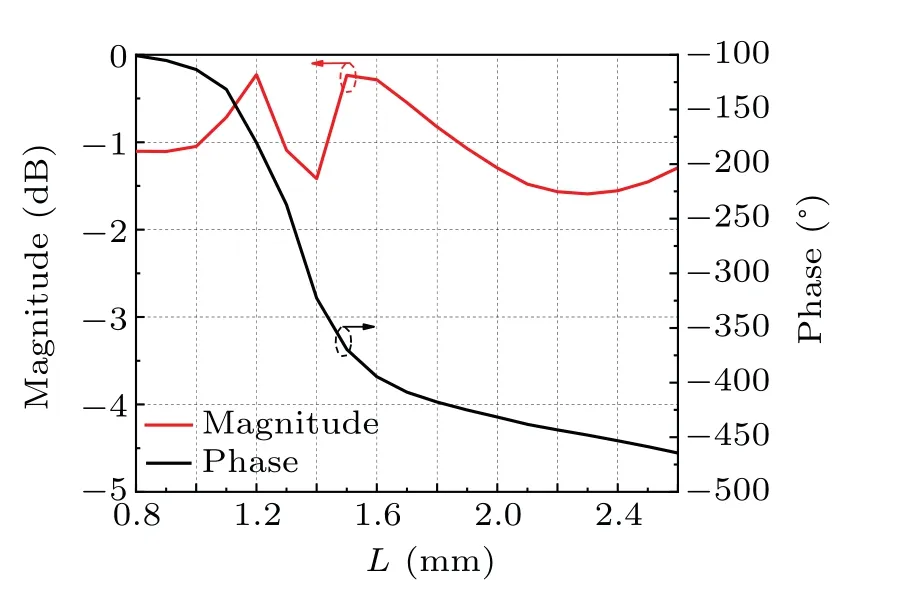
Fig.3. Magnitude and phase of transmission coefficient with different L.
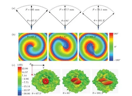
Fig.4. The bending angle analysis of the conformal transmitted metasurface,(a)the geometry of the conformal transmitted metasurfaces with different bending angles,(b)the simulation results of the electric field phase distributions with different bending angles,(c)the simulated 3-D far-field radiation patterns of the metasurfaces with different bending angles.
The length of the outer square isL,and the length of the center square is 0.25L. The distance from the original pointOto center of via holes isr. The size of the transmitted metasurface unit cell is 6.2 mm×6.2 mm×2 mm. The substrate is Wangling F4B teflon woven glass fabric copper-clad laminates with dielectric constantεr=2.65 and dissipation factor tanδ=0.003. The simulated transmission coefficient of the unit cell is shown in Fig. 3. When changingLfrom 0.8 to 2.6 mm,the transmitted element has a wide transmission phase shift range of 363.2°. The transmission phase shift range is from-100.6°to-463.2°with transmission magnitude below-1.6 dB.
In order to analysis the bending angle influence of the conformal transmitted metasurface,we generate vortex waves at different bending angles with the fixed OAM model=1.Figure 4(a)shows the geometry of the conformal transmitted metasurfaces with different bending angles on theXOZplane.Here,sizes of the metasurfaces are the same,whereas the distances from feed horns to the metasurfaces are difference. The working frequency is set at 24.125 GHz.Figure 4(b)shows the simulation results of the electric field phase distributions with different bending angles. Figure 4(c)shows the simulated 3-D far-field radiation patterns of the metasurfaces with different bending angles. We find that the larger bending angle of the metasurface will cause the worse far-field radiation pattern and electric field phase distributions of the generated OAM vortex wave.
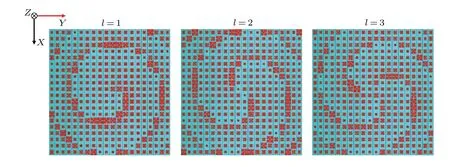
Fig.5. The cylindrical conformal transmitted metasurface distributions with different OAM modes.
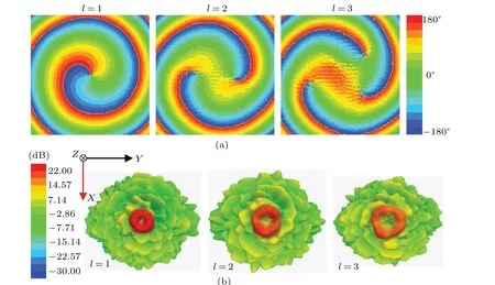
Fig.6. Simulation result of the cylindrical conformal transmitted metasurfaces of different OAM modes(a)electrical field phase distributions on the observational plane,(b)3-D far-field radiation patterns.
We further choose the bending angle of 67.5°to verify our conformal transmitted metasurface design,where the distance between the feed horn and the cylindrical transmitted metasurface is 105 mm. A cylindrical transmitted metasurface with 20×20 elements operating at 24.125 GHz is designed. The size of the observation plane is 400 mm×400 mm atz=1.5 m. Based on Eq. (1), the phase distributions on the cylindrical conformal transmitted metasurface with different OAM modes can be calculated. By compensating the phase distributions with corresponding transmitted unit cells,we can obtain topologies of cylindrical conformal transmitted metasurfaces,as shown in Fig.5. The simulated electric field phase distributions of different OAM modes on the observation plane is shown in Fig. 6(a), where the characteristics of different OAM modes can be easily recognized. Figure 6(b)shows the simulated 3D far-field radiation patterns of different OAM modes,and a key feature of OAM wave amplitude null can also be observed. Simulation results verify that the proposed cylindrical conformal transmitted metasurface can effectively generate OAM vortex waves.
3. Experimental verification
In order to verify the above analysis, a prototype of the proposed cylindrical transmitted metasurface with OAM mode numberl=1,2 and the bending angleθ=67.5°is fabricated and measured. The electric field amplitude and phase distributions on the observation plane are obtained by the planar nearfield scanning measurement method,as shown in Fig.7. Photograph of the conormal transmitted metasurface prototypes is shown in Fig.8. The amplitude distribution and phase distribution on the observation plane are shown in Figs.9(a)-9(d).We can see amplitude nulls and spiral phase distribution in the simulated and measured results,which are consistent with theory and design.

Fig.7. Configuration of the planar near-field scanning measurement system.
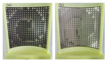
Fig.8. Photograph of the conormal transmitted metasurface prototype:(a)l=1,(b)l=2.
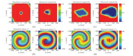
Fig.9. Simulated and measured electrical field results on the observational plane at 24.125 GHz,(a)l=1 magnitude distributions,(b)l=1 phase distributions,(c)l=2 magnitude distributions,(d)l=2 phase distributions.
4. Conclusion
In summary, we have reported a design for generating OAM vortex waves with cylindrical conformal transmitted metasurface whose element can achieve an excellent phase shift range over 360°. A formula for calculating the phase distributions of cylindrical conformal transmitted metasurface is proposed to generate OAM vortex waves. Simulated and measured results verify that the proposed cylindrical conformal transmitted metasurface can effectively generate OAM vortex waves. The proposed method and design can give a reference for OAM vortex wave generation in cylindrical conformal platforms.
Acknowledgements
This work was supported by the National Natural Science Foundation of China (Grant No. 61961006) and the Science Technology Foundation of Guizhou Province, China (Grant No.QKHJC[2020]1Y257).

- Chinese Physics B的其它文章
- Quantum walk search algorithm for multi-objective searching with iteration auto-controlling on hypercube
- Protecting geometric quantum discord via partially collapsing measurements of two qubits in multiple bosonic reservoirs
- Manipulating vortices in F =2 Bose-Einstein condensates through magnetic field and spin-orbit coupling
- Beating standard quantum limit via two-axis magnetic susceptibility measurement
- Neural-mechanism-driven image block encryption algorithm incorporating a hyperchaotic system and cloud model
- Anti-function solution of uniaxial anisotropic Stoner-Wohlfarth model