
Investigation on the multi-hole directional coupler for power measurement of the J-TEXT ECRH system
2022-07-13 00:37WentingWENG翁文婷DonghuiXIA夏冬辉YizheTIAN田一哲XixuanCHEN陈曦璇ZhijiangWANG王之江andYuanPAN潘垣
Plasma Science and Technology 2022年6期
关键词:之江
Wenting WENG (翁文婷),Donghui XIA (夏冬辉),Yizhe TIAN (田一哲),Xixuan CHEN (陈曦璇),Zhijiang WANG (王之江) and Yuan PAN (潘垣)
The International Joint Research Laboratory of Magnetic Confinement Fusion and Plasma Physics,State Key Laboratory of Advanced Electromagnetic Engineering and Technology,School of Electrical and Electronic Engineering,Huazhong University of Science and Technology,Wuhan 430074,People’s Republic of China
Abstract Power measurement is necessary for an electron cyclotron resonance heating (ECRH) system.The directional coupler method has been put forward to monitor high-power microwave from gyrotrons in real time.A multi-hole directional coupler has been designed and manufactured for the 105 GHz/500 kW ECRH system on the J-TEXT tokamak.During the design process,we established the relationships between hole parameters and coupling characteristics based on the multi-hole coupling method and small-hole coupling theory.High-power tests have been carried out.The results indicated the reasonability of the theoretical design and practicality of the fabricated directional coupler.Sources of test errors have been discussed in detail,and the influences of spurious modes on the directional couplers have been emphatically analyzed.
Keywords: directional couplers,power measurement,ECRH system
1.Introduction
In the area of plasma heating for tokamak devices,normally the microwave from the ECRH systems (28-170 GHz) [1-4]needs to be transmitted ten of meters distance before being injected into the tokamak device.To improve transmission quality,over-moded corrugated circular waveguides are often used as transmission lines due to their extremely low losses and low attenuation at high frequencies [1,2,5].A linearly polarized (LP) mode basis set can be introduced to describe the microwave in it,and the LP01mode is the fundamental mode that propagates with less attenuation than the other modes [6].Microwave information in the transmission lines can be used to monitor the work status of the gyrotrons and provide accurate parameters for physical experiment analysis in tokamaks.Microwave power is one of the essential microwave information.Its accurate measurement is an essential part of the ECRH system operation.
The microwave power from gyrotrons is in the tens to hundreds of kilowatts (kW).General power measurement instruments cannot directly be used for it.Typically,there are two methods for power measurement:the calorimetric method and the directional coupler method.The calorimetric method converts the microwave energy into water thermal energy and depends on non-real-time water temperature changes in the dummy load [7-10].While a fraction of the high-power microwave is coupled in the directional coupler method for measurement.The calorimetric method has the advantage of stable operation,but it suffers from water temperature fluctuation,water flow rate,etc.It cannot provide real-time power,only average power over time.The directional coupler method has an instantaneous response for the power,but it requires high processing technologies especially when it is used for high-frequency microwave measurement.They are suitable for different situations respectively.With the requirement of real-time high-power microwave power measurement here,we focus on the directional coupler method.
Some previous papers have presented different designed directional couplers for the over-moded corrugated waveguides [11-13],and the theories for coupling schemes have been previously developed [14-19].One of the commonalities is that the over-moded corrugated waveguides are assumed to ideally operate only in the LP01mode [6].However,excitation of the spurious modes is inevitable due to tilt or offset of the transmission lines.These spurious modes are supported in the line and propagate at different phase velocities together with the LP01mode.Their existence causes interference effects on the directional coupler,which will be analyzed in this work.
This work investigates the multi-hole directional coupler for the 105 GHz/500 kW ECRH system on the J-TEXT tokamak.The design principle and model are presented in section 2.Concrete design parameters and coupling characteristics,including directivity and coupling coefficient,are described and studied in section 3.Section 4 introduces high power tests with the calorimetric method and the polarizer,respectively.We analyzed error sources of the tests and discussed the influences from the spurious modes in detail.The reliability of the designed directional coupler and its calculated model have been verified with the test results.Finally,a brief summary has been given in section 5.
2.Model of the directional coupler
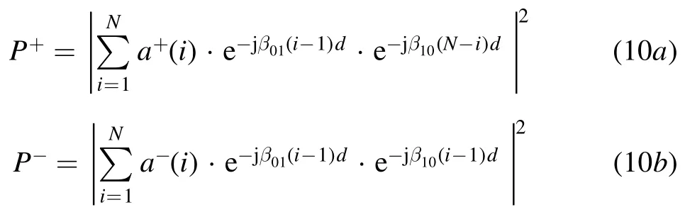
The directional couplers for the over-moded corrugated circular waveguides are generally integrated into a miter bend.Cross-sectional views of the typical coupling structure are shown in figure 1.The corrugated circular waveguides serve as the primary waveguides,while a rectangular waveguide serves as the auxiliary waveguide[12,13].The coupling hole array distributes symmetrically,and each coupling hole is equivalent to a cut-off circular waveguide for the microwave.When the microwave incident at a certain angle θ,a small fraction of them will be coupled into the auxiliary waveguide via the holes.The rest will be reflected and continue propagating in the following waveguide.
Parameters of the coupling holes are shown in figure 1,where riis the radius of the i-th hole,diis the distance between the center of the i-th hole and the central axis of the whole hole array,h is the hole depth.
Coupling coefficient and directivity are two of the most important factors for judging the performance of the directional coupler,which are defined as

where,P1is the incident power,is the coupled power,andis the power out of isolation port.These two factors represent the relative relationships between the power of different ports.
2.1.Basic principle
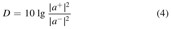
Coupling through holes is associated with the electric and magnetic field in the primary and the auxiliary waveguide.According to Bethe’s small-hole theory,the coupling occurs only when the normal electric field components,which are perpendicular to the hole array,or the tangential magnetic field components,which are co-directional to the hole array,co-exist and nonzero in both waveguides.When the microwave is coupled to the auxiliary waveguide,the coupling intensity of the forward and the backward wave for a single hole can be expressed as equation (2) [17],and the coupling coefficient and the directivity of a single-hole directional coupler can be calculated as equations (3) and (4).

where ω is the angular frequency,μ0is the free space magnetic permeability,and ε0is the free space dielectric constant.The power in both waveguides needs to be normalized to the same level for calculation,so the amplitudes of the electromagnetic field components in equation (2) are normalized values.E1nandrepresent the amplitudes of the normal electric field components in the primary and the auxiliary waveguide,H1u,H1vandcorrespond to the amplitudes of the tangential magnetic field components.Both muand mvrepresent magnetic polarizability,and pnrepresents electric polarizability[16].The prerequisite for Bethe’s smallhole theory is that hole diameters are much smaller than the microwave wavelength.Since the wavelength of the microwave from the gyrotrons is at the mm-level,the prerequisite cannot be satisfied,bringing errors to the coupling intensity,and Rmand Reneed to be introduced for correction [17].Correction factors Kmand Kealso need to be introduced because the attenuation effects of the coupling round holes to the coupled wave cannot be ignored [17].These factors are given by
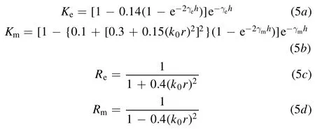
where r represents the hole radius,k0is the microwave wavenumber in free space.γeand γmare defined as propagation constants in the coupling round holes,and they both satisfy the following expression.
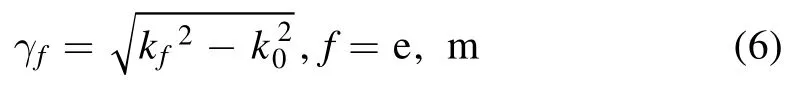
kf(f=e,m) is the cut-frequency wavenumber of the equivalent cut-off circular waveguide corresponding to the TM01mode and TE11mode,respectively [17].With the help of Bethe’s small-hole coupling theory,we can establish the calculation model for the multi-hole directional coupler.
2.2.Establishment of the model
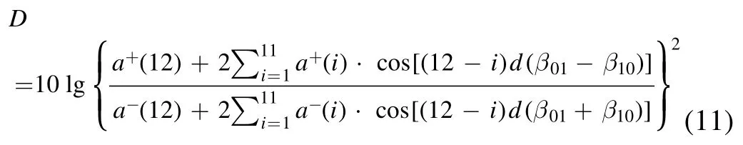
We drill the hole array on the broad side of the rectangular waveguide at the location of x=a/2,as shown in figure 2.The tangential magnetic field components H1zand H2zin the primary and auxiliary waveguide are equal to zero.While the tangential magnetic field components H1xand H2x,the normal electric field components E1yand E2yall exist in both waveguides.Therefore,magnetic and electric coupling will happen simultaneously in the present structure.
H1xand E1yare normalized electromagnetic field components of the dominant LP01mode in the primary waveguide,which can be calculated as equations (7) [6,20].

Here,Z=(μ0/ε0)1/2is the impedance of free space,and J0(x) and J1(x) correspond to the zero-order and first-order of the first kind Bessel function,respectively.u01is the first root of the zero-order Bessel function.R is the radius of the overmoded circular waveguide.
TE10mode is the only microwave mode in the rectangular waveguide for single mode transmission.Its normalized electromagnetic field components,which can be coupled at the location of holes,are expressed as equations (8) [21]:
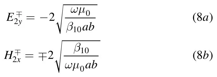
where,a is the broad wall value while b is for the narrow one,as shown in figure 2.β10is the phase constant of TE10mode.
Based on equations(2)-(8),the coupling intensity±aiof the i-th hole can be expressed as equation (9).

For the multi-hole directional coupler,phase delay should also be considered.So,with the phase superposition principle [22],the normalized total power of the forward wave P+excited by the hole array at the coupled port and of the backward wave P−at the isolation port are calculated as equations (10a) and (10b) respectively.
Here,N is the total number of the holes,d is the hole interval.β01=2πsinθ/λ0is the phase constant of the LP01mode when considering the incident angle,and here wavelength λ0corresponds to the operating frequency of the directional coupler.
Then,the relationships between the coupling coefficient and coupling hole parameters can be established according to the above analysis,and so is the directivity.Based on these,a set of computational codes has been developed to help design a directional coupler and observe its coupling performance.
3.Parameter design of the directional coupler
The directional coupler is often equipped with a detector.Since the detector can generally measure the coupled wave on the milliwatt level,the coupling coefficient of the directional coupler,which is designed for the 500 kW ECRH system is suitable in the range of −70 dB to −80 dB.Within this range,with the help of an adjustable attenuator,the detector can be prevented from being damaged and can make more accurate power measurements.Meanwhile,we need to consider whether the directional coupler can work properly when the microwave is shifted from the original operating frequency.So,the working bandwidth should be considered within which the change of the coupling coefficient should not exceed 3 dB,and the directivity within the working bandwidth is expected to be no less than 20 dB to ensure that the power out of the isolation port is far less than that of the coupled port.The frequency shift generally will not exceed±1 GHz for the gyrotron here,so the bandwidth of the designed directional coupler is required to be at least+/−1 GHz.In general,the bandwidth is the wider the better,and it describes the ability of power measurement over a range of frequencies.Accordingly,it is necessary to observe the frequency characteristics of the directional coupler.Taking the above requirements into consideration,we can design the directional coupler with the help of the developed computational codes.
Different hole parameters have various degrees of influence on the coupling coefficient and directivity.Bigger and more holes can increase the coupling area.So,the hole diameters and number have incremental impacts on the coupling coefficient.But the hole depth has the opposite effect,the increase of it will cause more loss of the coupled wave.The directivity is mainly decided by the hole interval.By adjusting the hole interval,the forward wave power from each coupling hole can be added to each other at the coupled port,or the backward ones can be cancelled out at the isolation port.
Furthermore,parameter selections of the hole array are restricted by machining accuracy which generally can only reach 0.01 mm at most,and each hole parameter also has their own restrictions which need to be fully considered in the design.
For the hole depth,the decreasing of it can obtain higher coupling coefficient but will cause possible high difficulties in machining and possible thermal deformation in usage.After comprehensive consideration,we choose 1 mm as the hole depth.To yield wider working bandwidth,the design method of the equal-interval and unequal-intensity hole distribution is adopted,and Chebyshev distribution is used as the intensity distribution function [19].Considering the requirements above and the size of the directional coupler synthetically,repeating the calculations with the model,the final calculated diameters of the 23 holes range from 0.54 mm to 0.66 mm,the smallest are at the two ends and increase towards the center gradually.
The hole interval should be greater than the maximum hole diameter to avoid holes overlapping with each other and less than half wavelength (λ0/2) to eliminate high order diffraction modes [11].Since the hole array distributes symmetrically about the 12-th hole which is located at the central axis,the directivity of the designed directional coupler can be finally derived mathematically as equation (11).
Only the hole interval d is unknown in equation (11),so we can obtain the wanted directivity by adjusting its value.With repeated calculations,we choose 1.14 mm as its final value to achieve higher directivity.
Then,model WR-08 standard rectangular waveguide is selected because single mode transmission can be realized in it at 105 GHz.Finally,we can use the computational codes to check the performance of the designed directional coupler.
As shown in figure 3,the calculated directivity is in excess of 30 dB near the central frequency 105 GHz.The coupling coefficient at 105 GHz is about −72.4 dB and its maximum variation value in the range of ±5 GHz is about 2 dB.Since the directivity and the coupling coefficient within working frequency range of 105±5 GHz can meet the design requirements,the working bandwidth is at least from 100 to 110 GHz.
4.High power tests of the directional coupler
The directional coupler used for power measurement has been fabricated,as shown in figure 4.It has an array of holes drilled along the central line on the front side and two rectangular holes used as the output port on the back side.
High power tests of the directional coupler are on the 105 GHz/500 kW ECRH system,which is used for plasma heating.An adjustable attenuator and a detector have been connected at the coupled port successively to measure the coupled wave,as shown in figure 5.
4.1.Tests with the calorimetric method
Due to limitations of the manufacture technology,the fabricated directional coupler has inevitable machining errors,making actual coupling coefficients not strictly equal to the theoretical one.Generally,the calibration method can be introduced when the actual coupling coefficients have some deviations from the theoretical one.However,the calibration method will only become available when a directional coupler has a good linearity.So,it is necessary to verify the linearity of the directional coupler.
Since the power measured by the calorimetric method can be considered comparatively accurate,we can calculate the experimental coupling coefficients with its help.If the results indicate that the fabricated directional coupler needs to be calibrated,the calorimetric method can also help observe the linearity of the coupler.
To obtain the actual coupling coefficients,we need to measure the incident power with the calorimetric method and the directional coupler respectively.A simplified view of the detailed steps is shown in figure 6.The high-power microwave is produced by the gyrotron.When it is transmitted to the tokamak device for plasma heating,a little part will be coupled by the directional coupler and measured by the matched detectors.Then under the identical parameters,the microwave will be injected into the dummy load,and we can use the calorimetric method to obtain the comparatively accurate microwave power which can be approximately considered as the incident power for the directional coupler.
The tests are carried out in 100 ms/105 GHz pulsed power.Repeated tests show that the actual coupling coefficients of the designed directional coupler under different incident power are roughly equivalent,and the average value is −70.21 dB.It is obvious that the fabricated directional coupler needs to be calibrated,and the linearity of the directional coupler can be observed by fitting the signal intensities of the detector under different incident power.The fitting results of the high-power tests are shown in figure 7.
The fitting curve for the normalized results demonstrates that such a fabricated directional coupler has a good linearity.Although there is a certain error between the actual and theoretical values of the coupling coefficient,the fabricated directional coupler can reflect the variation of wave power greatly.So,the directional coupler can measure the microwave power more accurately after calibration.
Meanwhile,the power out of the isolation port is suppressed to a very low level and almost cannot be measured by the detector.But we can confirm that the power out of the isolation port is less than 1/100th of the coupled power,and the directivities can at least exceed 20 dB.It indicates that the wave that leaks from the holes mainly propagates in the forward direction along the rectangular waveguide while rarely in the backward direction.So,we can consider that the fabricated directional coupler can realize directional energy transmission and meet the design requirement of no less than 20 dB directivity.
In conclusion,we can preliminarily confirm that the model is effective and the fabricated directional coupler can realize power measurements reliably.
4.2.Tests with a linear polarizer
To study whether the fabricated directional coupler can sense the power variation on a smaller scale,a linear polarizer integrated into a miter bend has been set before the directional coupler along the transmission line to change the incident power for the directional coupler.
The linear polarizer can change the electric field components of the microwave[23-26].The relationships between the electric field of the incident wave (Exi,Eyi) and of the reflected wave (Exr,Eyr) for the polarizer are related to the rotation angle Φ,the incident angle θ,the period p and the depth dp,as shown in figure 8[24].θ,p and dpare immutable for the polarizer after installation.So,we can rotate the polarizer to change the electric field components of the reflected wave.
Polarizer’s reflected wave will be transmitted to the following directional coupler along the transmission line and then act as the incident wave of the directional coupler.Figure 9 shows the layout of the polarizer and the directional coupler,and the relationships between the microwave electric field directions in the polarizer and in the directional coupler.
Figure 1.Structure of the directional coupler.(a) The top view of the hole array,(b) the side view of the hole array,and (c) the overall structure of the coupler.
Figure 2.Coordinate system of the coupling area and the electromagnetic field components directions.
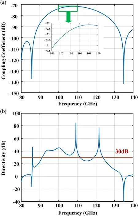
Figure 3.Calculated frequency characteristics of the designed directional coupler.
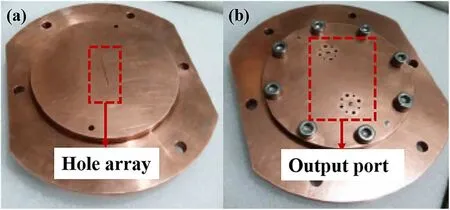
Figure 4.Photographs of the fabricated directional coupler.
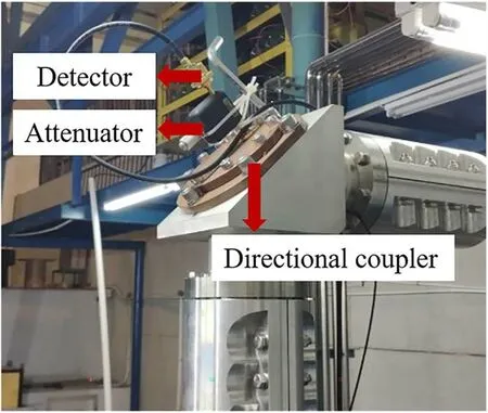
Figure 5.Photograph of the directional coupler integrated in the meter bend.
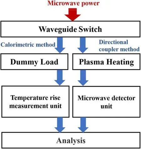
Figure 6.Process of analysis.

Figure 8.Parameters of the polarizer.(a) Schematic of sinusoidal grooves for the polarizer,(b)schematic of the polarizer.(Exi,Eyi)and ki are the electric field components and the wave vector of the incident wave for the polarizer.(Exr,Eyr)and kr are the electric field components and the wave vector of the reflected wave,respectively.
Intensities of the electromagnetic field components that can be coupled to the rectangular waveguide vary with the electric field components of the reflected wave from the polarizer,leading to the variation of the coupled wave power as the polarizer rotates.
In this test,we need to keep the output power from the gyrotron constant and change the rotation angle of the polarizer at intervals of 10°.The coupled wave power will vary with the polarizer rotation angles,and the experimental and numerical calculation results are shown in figure 10.The test results show great agreement with the numerical curve,the errors between them are acceptable.The results indicate that the designed directional coupler can correctly sense changes of the incident wave power and its electromagnetic fields.The feasibility of the model and the effectiveness of the fabricated directional coupler are further proven.
4.3.Error analysis
There are two identical sources of errors between the measured and theoretical values in the above two tests.One of the error sources is the machining error of the holes.Limited machining accuracy makes the actual coupling characteristics different from the theoretical ones,and some of the manufactured holes are not standard round holes,and their magnetic polarizabilities and electric polarizabilities cannot be calculated accurately.Another error source is that only the coupling of the LP01mode has been considered in the design process.However,various modes can propagate in the over-moded corrugated waveguides.Most higher-order spurious modes will be attenuated after travelling certain distances,while some lower-order spurious modes will propagate with small attenuation and can arrive at the directional coupler.These lower-order spurious modes can affect coupling characteristics to a certain extent.In addition,the errors in the tests with the polarizer also come from the different losses of the polarizer at different rotation angles and slight fluctuation of the output power from the gyrotron.
Next,the influence of the lower-order spurious modes on the directional coupler will be discussed in detail.Figure 11 shows the coordinates used in describing these modes.The microwave modes propagate in the z-direction,and their normalized electric field in the over-moded corrugated waveguide can be expressed as equation (12) [6]:

Figure 9.(a) Directions of the electric field component for the incident wave and reflected wave in the polarizer.ki and kr represent wave vectors,(b) directions of the electric field component for the incident wave in the directional coupler,(c) a simplified diagram of the layout for the polarizer and the directional coupler.The microwave from the gyrotron propagates along the arrow direction.
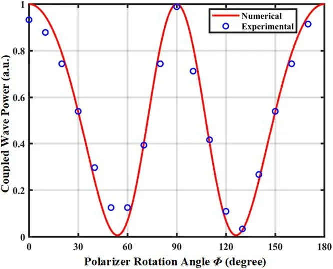
Figure 10.The dependence of the normalized coupled wave power on polarizer rotation angles.
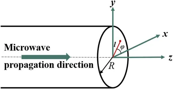
Figure 11.Coordinates for the propagating modes.The (x,y)coordinates have been set in the plane perpendicular to the z-axis which is parallel to the central axis of the transmission line.
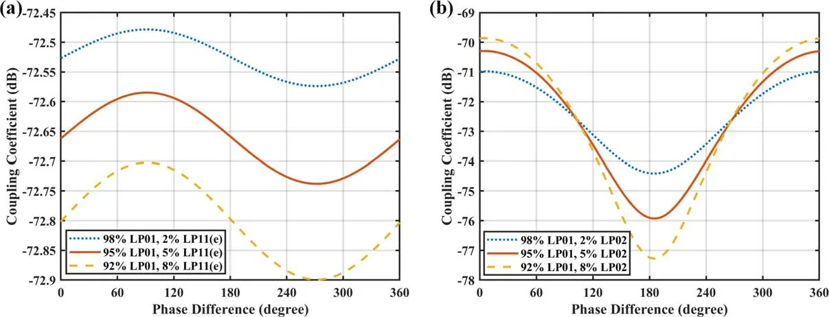
Figure 12.(a) The coupling coefficient varies with phase differences between the LP01 mode and the LP11(e) mode,(b) the coupling coefficient varies with phase differences between the LP01 mode and the LP02 mode.
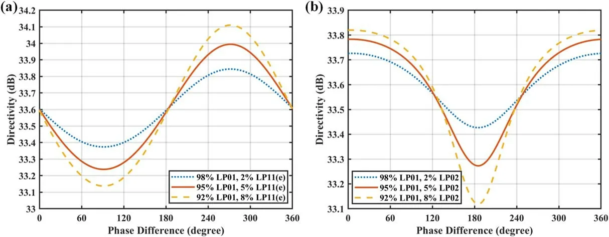
Figure 13.(a)The directivity varies with phase differences between the LP01 mode and the LP11(e)mode,(b)the directivity varies with phase differences between the LP01 mode and the LP02 mode.

Figure 14.Mode amplitude distributions of the LP01 mode,the LP02 mode and the LP11(e) mode in the cross section of the over-moded corrugated waveguide.

where Npmand βpmindicate the normalized coefficient and the phase constant of the LPpmmode respectively.Jp(x)is the p-order Bessel function of the first kind,and upmis the m-th root of the p-order first kind Bessel function.l is the distance from the central axis of the over-moded corrugated waveguide.θpmis the phase of the LPpmmode at z=0.eiis the unit vector in the i-axis (i=x,y) and represents the polarization direction of the microwave.Equation (12) also suggests that these modes propagate with different phase velocities in the transmission line.Hence,the phase differences of the electromagnetic fields between modes exist and vary with different locations.In multi-mode transmission,both phase differences and proportions of the modes will affect the microwave electromagnetic field distributions in the circular waveguide,which is closely related to the coupled wave power for the directional coupler.
When the modes arrive at the directional coupler,we can take the LP01mode as a reference and define the phase differences for the other modes as Δφpmto simplify the formula deduction.Δφpmgoes from 0° to 360°,corresponding to different locations.Whether the electromagnetic fields of the LPpmmode can be coupled depends on the polarization direction and the coupling structure of the directional coupler.Taking y-direction as the polarization direction of the electric field,combined with the coupling structure shown in figure 2,for example,we can establish the calculation model for the multi-mode transmission,and the other cases can be analyzed similarly.
Under the above assumptions,the normal electric field components and the tangential magnetic field component associated with the i-th coupling hole and LPpmmode that can be coupled can be derived as equation (13):

where Apmis the relative power in the circular waveguide of the LPpmmode.Meanwhile,distribution and normalized intensity of the electromagnetic field in the rectangular waveguide remain constant with equation (8).With the reference of equation (2),the coupling intensitya±pm(i,φ,Δφpm)associated with the i-th coupling hole and LPpmmode can be derived.
And then,the total coupling intensities A±of different modes from each coupling hole superimposed with each other at the coupled port and the isolation port are calculated as:

Based on the above equations,we can calculate the coupling coefficients and the directivities of the directional coupler when we consider the multi-mode transmission.
Ideally,the over-moded corrugated waveguides operate only in LP01mode,but the spurious modes will inevitably be excited due to the slight offset or tilting of the line and so on.The experimental microwave source’s poor operating condition and transmission line’s poor alignment will typically cause higher proportions of the spurious modes to be excited.The spurious modes mainly consist of LP02mode,LP11(e)mode and LP11(o)mode[6,27].The mismatch between beam radius and waveguide diameter mainly excites the LP02mode[22,27].Titled or offset input wave or misalignments of the transmission line mainly excite the LP11modes [22,27].So,we can take the LP02mode,LP11(e)mode and LP11(o)mode separately as examples for all the discussions and illustrations to investigate the influence of the spurious modes on the directional coupler.
Sometimes the LP11(e)mode or the LP11(o)mode cannot be coupled by the holes because whether they can be coupled mainly depends on the polarization direction of the incident wave and the direction of the hole array.However,the LP11(e) mode and the LP11(o) mode share the same electromagnetic field amplitude distribution in the cross section of the over-moded corrugated waveguide.So,they have the same analysis results when superposition with the LP01mode separately.Here,the y-direction is defined as the polarization direction of the incident wave for the designed directional coupler in this 500 kW/105 GHz ECRH system and only LP11(e)mode can be coupled out from the hole array.So,we can take the LP11(e) mode as an example to discuss the influence of the LP11modes on the directional coupler.
Variations of the coupling coefficients and the directivities with different phase differences (Δφpm) under different proportions should be observed with the designed directional coupler.When we added some typical mode proportions to the model,the calculated results are shown in figures 12 and 13.The results indicate that the existence of the spurious modes will cause fluctuations of the coupling coefficients and the directivities.The ranges of the fluctuations are much wider when the wave has a relatively lower purity of LP01mode.The spurious modes mainly affect the coupling coefficient,and their effects on the directivities are minimal and can be neglected,as shown in figure 13.This is because the fluctuations of the forward wave and the backward wave have a similar tendency.
Through a comparative analysis of the fluctuations caused by the LP02mode and the LP11(e)mode,the LP02mode shows more influence on the coupling coefficients than the LP11(e)mode.This is fundamentally caused by the location and distribution of the hole array.The LP11(e) mode can be strongly coupled at the left and right sides of the central axis in the directional coupler but can be suppressed at the coupled port due to the 180° phase difference of the electromagnetic field between two sides,as shown in figure 14.Since the phase delay cannot be ignored when the wave propagates in the rectangle waveguide,the LP11(e)mode coupling still has some effects on the coupling coefficients.The LP02mode cannot be suppressed in this directional coupler,bringing larger fluctuations for the coupling coefficients.
It is difficult to obtain accurate phase differences and proportions of each spurious mode in the ECRH system,so the coupling coefficient and the directivity calculated by the model deviate from the actual values.
The above analysis convincingly proves that the errors between the measured and theoretical values in the tests partly come from the existence of the spurious modes.To reduce the impacts of the spurious modes on the designed directional coupler in the ECRH system,we can develop selective-mode directional couplers [22].The selective-mode directional couplers should only couple the LP01mode and suppress all the other lower-order spurious modes to reduce their effects on the coupling performance to as small as possible.
5.Conclusions
A 23-holes directional coupler has been designed and fabricated for the 500 kW/105 GHz ECRH system on the J-TEXT tokamak to realize real-time power measurement.A calculated model has been established based on the small-hole coupling theory and phase superposition principle to study the influence of the hole parameters on the coupling characteristics.To verify the reliability of the model,the fabricated directional coupler has been tested with the calorimetric method.The sensitivity and accuracy of the fabricated directional coupler have been verified by testing with the linear polarizer.The test results agree with the theoretical ones in the range of the errors permitted.The test errors between the theoretical and the actual values of the coupling coefficients,at least in part,are caused by the existence of the spurious modes.So,the influences of the spurious modes on the directional coupler have also been analyzed in detail,and the future direction of the directional coupler for the overmoded corrugated waveguides has finally been put forward.
Acknowledgments
This work was supported by the National Key Research and Development Program of China(Nos.2017YFE0300200 and 2017YFE0300204),and in part by National Natural Science Foundation of China (No.51821005).
猜你喜欢
中国造纸(2022年8期)2022-11-24
电影评介(2022年6期)2022-09-28
——以张之江爱国之志为主线
天津体育学院学报(2021年5期)2021-11-24
中国篆刻·书画教育(2021年6期)2021-07-25
中国篆刻·书画教育(2021年5期)2021-07-05
科学导报(2020年49期)2020-09-08
美与时代·美术学刊(2020年5期)2020-08-06
股市动态分析(2018年39期)2018-10-24
民族文学(2017年9期)2017-10-09
中国建筑金属结构(2011年6期)2011-01-31
 Plasma Science and Technology2022年6期
- Plasma Science and Technology的其它文章
- Recent progress on the J-TEXT three-wave polarimeter-interferometer
- Design of the stripping unit and the electromagnetic analysis unit for the E//B NPA on HL-2A/2M tokamak
- Space-resolved vacuum-ultraviolet spectroscopy for measuring impurity emission from divertor region of EAST tokamak
- Development of a combined interferometer using millimeter wave solid state source and a far infrared laser on ENN’s XuanLong-50(EXL-50)
- Bench test of interferometer measurement for the Keda Reconnection eXperiment device (KRX)
- Neutron yield measurement system of HL-2A tokamak