
Wide-range characteristics of beam perveance and saddle point potential of LIPS-200 ion thruster
2022-11-17 02:59XueerZHANG张雪儿TianpingZHANG张天平DetianLI李得天JuanjuanCHEN陈娟娟andYanhuiJIA贾艳辉
Plasma Science and Technology 2022年11期
Xueer ZHANG(张雪儿),Tianping ZHANG(张天平),Detian LI(李得天),Juanjuan CHEN(陈娟娟)and Yanhui JIA(贾艳辉)
Science and Technology on Vacuum Technology and Physics Laboratory,Key Laboratory of Space Electric Propulsion Technology of Gansu Province,Lanzhou Institute of Physics,Lanzhou 730000,People’s Republic of China
Abstract Both the long-life and multi-mode versions of LIPS-200 ion thruster are under investigation in LIP(Lanzhou Institute of Physics).To confirm the feasible ranges of the beam current and accel(abbreviation for accelaration)grid potential to apply to the thruster,the wide-range beam perveance(the state of beam focus)and saddle point potential(the lowest potential along beamlet centerline)characteristics of LIPS-200 are studied with a test-verified PIC-MCC(Particle in Cell-Monte Carlo Collisions)model.These characteristics are investigated with both the initial and the eroded states of the accel grid aperture diameter.The results show that the feasible ranges of these parameters with respect to perveance/crossover(overfocused)limit extend as the operating time accumulates,while the feasible range of accel grid potential narrows due to a reduced EBSF(electron backstreaming failure)margin.The feasible ranges determined by the initial condition are:(i)the beam current up to 0.981 A,and(ii)the accel grid potential up to-85 V.A 23% enlargement of the aperture diameter would bring up to 48 V of EBSF margin loss.
Keywords:ion thruster,perveance limit,crossover limit,saddle point potential,parameter range
1.Introduction
Wider operating range,more operating modes,and longer lifetime are the major trends for ion thruster,which also extend the advantages of ion thruster compared to other types of electric thrusters[1].The principles for multi-mode ion thrusters to achieve extended lifetime include(i)during widerange operation,the ions are always extracted by the ion optics without direct impingement on the grids,which is characterized with the beam perveance;(ii)the soft failure(whose damage to the thruster is not permanent)due to electron backstreaming does not occur,i.e.the saddle point potential(Vsp,the lowest potential along beamlet centerline)is lower than the critical saddle point potential(Vsp*);(iii)grid structure failure(GSF)and electron backstreaming failure(EBSF)caused by sputtering erosion occur nearly simultaneously,which maximizes the lifetime.
Beam perveance(the state of beam focus)characteristics directly affect the performance of gridded ion thrusters,while saddle point potential characterizes the grid lifetime.Based on the life tests of multi-mode ion thrusters NSTAR(NASA Solar Technology Application Readiness)and NEXT(NASA’s Evolutionary Xenon Thruster)[2,3],numerical studies on the simulation of ion optics were conducted[4-6].Wilburet al[7]conducted an experimental study on two-grid optics sets and measured the perveance and crossover(overfocused)beamlet current limits.Emhoet al[8]applied different ion optics models for perveance study to the NEXT ion engine and obtained similar results.Yimet almade an uncertainty quantification of the modeled EBSF lifetime for the NEXT ion thruster[9].Goebelet alstudied the development and application of the multi-mode XIPS-25 ion thruster[10].
In China,the beam perveance and saddle point potential characteristics of LIPS-200,LIPS-300 and LIPS-400 ion thrusters were studied.Jiaet almade a numerical analysis of the EBSF threshold of LIPS-200[11].Chenet alanalyzed the numerical simulation results of LIPS-200 life test[12].Longet al[13]performed theoretical and experimental studies on the dynamic characteristics of beam perveance under thermal deformation in a three-grid ion thruster.Jiaet almade 2D hybrid-PIC simulations of the two-grid and three-grid ion optics[14].Chenet alstudied the optimization of the accel(abbreviation for accelaration)grid potential of LIPS-300 ion thruster[15].Zhaoet alconducted an experimental study on the multi-mode ion thruster LIPS-400[16,17].Sunet alstudied how the design parameter of three-grid ion optics affected the thruster lifetime[18].Jiaet almade a sensitivity analysis of the EBSF-related parameters for a three-grid ion thruster[19].Luet aldeveloped a set of highly reliable 3D simulation tools for both the ion optics[20]and the discharge chamber[21,22]of ion thrusters based on the immersed finite element method[23].They analyzed the variation of the grid erosion characteristics[24,25]and the Mo atom pollution under various operating conditions[20],which are of great significance.
LIPS-200 is the most technically mature ion thruster in China.By quantifying the lifetime and reliability of LIPS-200 ion thruster based on test-verified models,its critical failure modes are confirmed to be GSF and EBSF[12,26,27].To achieve an ultimate lifetime of 20 000 h under the restriction of remaining its readiness level,the constant-accel-potential and stepping-accel-potential methods have been presented and validated by test-verified life models[28].The mechanism of these methods is to adjust the accel grid potential and make GSF and EBSF occur at the same time[27].LIPS-200E ion thruster,the multi-mode version of LIPS-200,is designed for high-Earth orbit communication satellites[29,30].Except for the existing operating mode(40 mN/3000 s),LIPS-200E is capable to operate with 60 mN/3500 s.This requires the thruster to operate with wide-range parameters.Based on the test results and a verified numerical model of the single-mode version of LIPS-200[11,12,31],its beam perveance and saddle point potential characteristics with wide-range parameters will be studied in this work.These parameters include accel grid potential,accel grid aperture diameter,and upstream plasma density.The results will provide reference to the lifetime optimization of LIPS-200 and its multi-mode ion thruster.
2.Ion optics model and model verification
2.1.Ion optics and perveance fraction
LIPS-200 is a two-grid ion thruster with flight-readiness level.Its ion optics serve to extract and accelerate the ions in the upstream plasma.Most of the ions are ejected downstream as beam ions,while the rest impinge on the screen grid.When perveance or crossover limit occurs,part of the beam ions will impinge on the accel grid and generate impingement current[32].
The maximum amount of beamlet current that could be extracted is characterized with[32]

where
andPHis the perveance fraction,mthe ion mass,ethe electron charge,ε0the vacuum permittivity,Jbthe beamlet current,VTthe total accelerating voltage,lethe effective ion acceleration length,dsthe screen grid aperture diameter,Vsthe screen grid potential,Vpthe discharge voltage,Vathe accel grid potential.
Equations(1)and(2)show thatPHis related toVaandJb,whereJbis related to accel grid aperture size and upstream plasma density.Perveance limit occurs asPHgets close to 0,while crossover limit occurs asPHgets close to 1.Perveance(or crossover)limit means that the ions just impinge on the upstream(or downstream)side of the accel grid aperture.
2.2.Ion optics model
The computational domain of the ion optics model is shown in figure 1.This domain includes the screen and accel grid apertures at the center,where the worst-case erosion occurs.The influence of the radial nonuniformity in plasma parameters on the beam current is minimized by applying the tested beam flatness(the average beam current density divided by the maximum beam current density)to the beam current calculation.The influence on other parameters is not directly addressed,which might be a source of the calculation error.Only one beamlet is simulated numerically in the domain shown in figure 1 along the(r,z)radial and axial directions.The left boundary is set at the sheath surface in the discharge chamber with a potential ofVs+Vp,whereVpis the plasma potential in the discharge chamber.The radius and thickness of the screen and accelerator grid apertures are indicated byrs,raandts,ta,respectively.The boundary condition at the beamlet centerline is∂ϕ/∂n=0,wherenrepresents the normal direction.
The beam ions are modeled as moving particles,and its flux along the beamlet centerline direction is recorded.The beamlet current is collected at the right boundary.The beamlet diameter is recorded both at the upstream surface of accel grid and at the right boundary.
The electrons are modeled as thermal equilibrium fluid,which follows Boltzmann distribution.Within the computational domain,electrons only exist in the upstream area of screen grid and the downstream area of accel grid.The electron densityneis obtained with its relationship to potential ϕ,i.e.the Boltzmann equation.
The electric field is solved with a finite difference method in the format of five-point central difference,as shown in figure 2.The mesh size in both directions ish.The difference equation is derived as

where subscriptsiandjrepresent the node number,niandneare the number densities of ions and electrons,respectively.
Equation(3)is solved with Gauss-Seidel iteration method.The potential distribution is updated with the extraction process.Both the potential distributions through the field and along the centerline are recorded as a reference.A more detailed description of this model is given in[12,31].
2.3.Model verification
The parameters of LIPS-200 involved in this model are shown in table 1[12,24,26],where the rated values are consistent with the existing product.The accel grid aperture size was measured during the life test[12,26].
The model is validated with the 12 000 h life test of LIPS-200 ion thruster.The electron backstreaming limitVebsis defined as the accel grid potential where further decreases in its absolute value will give rise to a measurable increase in the beam current,which characterizes EBSF.This criterion is used in the model as
Table 1.LIPS-200 parameters.

where ε characterizes the calculation accuracy.Vspis updated with the potential distribution,whileVsp*is determined by[33]

whereVbpis the beam plasma potential,Tethe downstream electron temperature,febsthe backstreaming-to-beamlet current ratio,methe electron mass,Vdpthe plasma sheath potential.
The result is compared to the data collected in the life test,as shown in figure 3.The abbreviations‘Cal.’and‘Exp.’represent‘calculation’and‘experiment’,respectively.The calculated and experiment results show the same tendency.The largest deviation is 17.52%,while the root mean square deviation is 9.59%.This deviation arises from both the measurement error and the model simplification.Relative model simplifications include(i)constant grid potentials,(ii)neglected potential variation due to the change in grid mass,(iii)hot grid gap consistent with the measurement from the edge,and(iv)neglected multi-charged ions.
Except for electron backstreaming limit,the model is also verified with the beam current.The results are respectively shown in the next section.The beam current is obtained with the beamlet current calculated with this model,the number of grid apertures,and the tested beam flatness.The calculated results show good agreement with the test data.Thus,the accuracy of this model is acceptable.
3.Results and discussion
3.1.Wide-range beam perveance characteristics
Beam perveance is sensitive to the accel grid potential,accel grid aperture diameter,and the upstream plasma density.Within the reasonable ranges of these parameters,crossover or perveance limit may occur to the ion beamlet.
3.1.1.Beam perveance with accel grid potential.As shown in figures 4 and 5,both the beam and impingement currents show an obvious change at the accel grid potential of-75 V.This change is due to the perveance limit of the ion beamlet,which is shown in figure 6.In figures 6,9 and 12 are represented the contour colour plots of steady state ion flux(in particles per second)within the simulation domain of figure 1.Before this perveance limit occurs,the beam current basically decreases as the accel grid potential increases.Because the electric field accelerating the ions weakens as the accel grid potential is biased more positive.Then the number of the extracted ions per second decreases,which leads to the decrease in the beam current.To avoid perveance limit,the accel grid potential of LIPS-200 should be lower than-85 V when other conditions are rated.
Accordingly,the beamlet diameter(dimensionless throughout this article)increases as the accel grid potential increases,as shown in figure 7.Because thez-direction speed of the ions decreases as the electric field weakens,leading to a relatively largerr-direction displacement.When perveance limit occurs,the beamlet diameter decreases as the ions near the accel grid are intercepted.
3.1.2.Beam perveance with upstream plasma density.As shown in figure 8,both the beam and impingement currents show an obvious turning point at the upstream plasma density of 1.4×10¹⁷m-3.This turning point is due to the crossover limit of the ion beamlet,which is shown in figure 9.The critical plasma density where crossover limit occurs corresponds to a beam current of 0.981 A,which is about 16.7%higher than the rated value for LIPS-200.To avoid this crossover limit,the mass flow rate and discharge current of the thruster should be controlled within a proper range.
Before this crossover limit occurs,the beam current increases as the plasma density increases because the number of the ions to be extracted increases.The beamlet diameter also increases for the same reason,as shown in figure 10.Once the crossover limit occurs,the majority of these increased ions are absorbed by the accel grid,while the minority escape or impinge to other structures.Thus,the beam current is stabilized near 0.675 A as the plasma density becomes greater than 2.6×10¹⁷m-3.
3.1.3.Beam perveance with accel grid aperture diameter.As shown in figure 11,both the beam and impingement currents show an obvious change at the accel grid aperture diameter(dimensionless throughout this article)of 2.7.According to the ion flux distribution shown in figure 12,the cause of this change is confirmed to be the perveance limit of the ion beamlet.Before this perveance limit occurs,the beam current slightly increases as the aperture diameter decreases.Accordingly,the beamlet diameter slightly decreases as the aperture diameter decreases,as shown in figure 13.
3.2.Wide-range saddle point potential characteristics
The potential distribution near the saddle point is related to both the accel grid potential and the upstream ion beam.As the influence of the accel grid potential becomes weaker,as shown in figure 14,the upstream ion beam raises the potential and‘pushes’the saddle point downstream.The experimental data is the initial electron backstreaming limit of LIPS-200,corresponding to a critical saddle point potential of-8.2 V.It is also noticed that the saddle point potential is almost linearly related to the accel grid potential.This result is consistent with the expression of the relationship between saddle point and accel grid potentials in[5,33].
As shown in figure 15,the saddle point potential shows a turning point when the crossover limit occurs.Before this crossover,the saddle point position tends to move upstream as the upstream plasma density increases.This is considered to do with the downstream plasma,which also becomes denser as the upstream plasma increases.The safety margin against EBSF keeps over 80 V throughout this plasma density range.
The saddle point potential first decreases numerically with the increasing plasma density,and then turns to increase.The mechanism of the former is clear,which is a stronger effect of the beam ions on the potential distribution.As to the latter,the cause is still the ion distribution,but in a crossover state.As shown in figure 9,the ion flux near the barrel surface is about 3 times the one at the centerline.Thus,the majority of the ions are‘dispersed’rather than move along the centerline,leading to a drop in the saddle point potential.
In figure 16,the electric potential of the saddle point(solid bullets,left axis)and its axialzcoordinate(solid diamonds,right axis)are represented for different accel grid aperture diameters.The effect of enlarging the accel grid aperture size on the saddle point is similar to that of increasing the accel grid potential.As the accel grid aperture diameter increases,the potential of the saddle point drops numerically,while its position moves downstream.Since the negatively biased accel grid potential moves farther away from the centerline,the ion beam takes more of the dominant role.
3.3.Wide-range characteristics considering accel grid barrel erosion
The original accel grid aperture diameter of LIPS-200 is 3.0.The results in figures 11 and 16 show that the beam perveance and saddle point potential characteristics are sensitive to the accel grid aperture diameter.Therefore,these wide-range characteristics should be re-investigated as the accel grid aperture diameter enlarges with the sputtering erosion of charge exchange(CEX)ions.The characteristics of the eroded grid are studied,while the sputtering erosion process is not involved in this study.The case of 11 000 h of cumulative operating time is considered,after which the aperture diameter became 3.7[12],increasing by 23%compared with the initial value.
As shown in figures 17 and 18,the beam current and saddle point potential remain the same tendency with the accel grid potential after the barrel erosion.However,the perveance limit no longer shows up as the accel grid potential increases.The electron backstreaming limit is-115 V with the enlarged accel grid aperture,decreasing by 40 V compared with the initial case.
After the barrel erosion,the crossover limit does not show up until the upstream plasma density reaches 2.0×10¹⁷m-3,corresponding to a beam current of 1.198 A.This critical value increases by 22%compared with the initial case,as shown in figures 19 and 20.The safety margin against EBSF decreases by 24-48 V with the enlarged aperture diameter,yet still remains a margin greater than 40 V throughout this plasma density range.
3.4.Discussions on engineering application
Compared with single-mode LIPS-200 ion thruster,its multimode version operates at different conditions.First,the upstream plasma density is adjustable to realize multiple modes,which reflects on the beam current.Second,the accel grid potential is adjustable to optimize grid performance and lifetime.Third,as operating time accumulates,the accel grid aperture diameter will enlarge due to the sputtering erosion of CEX ions.With these conditions,the beam perveance and saddle point potential characteristics required to achieve long life of the multi-mode ion thruster are discussed as follows.
(i)Perveance or crossover limit should be avoided with widerange plasma density and accel grid potential.The results in figures 8-10 show that the maximum upstream plasma density to avoid crossover limit is 1.4×10¹⁷m-3,corresponding to the beam current of 0.981 A.With the rated accel grid potential,perveance limit does not occur within the plasma density range of 1×10¹⁵-4×10¹⁷m-3.The results in figures 4-7 show that the maximum accel grid potential to avoid perveance limit is-85 V,while crossover limit is not sensitive to the accel grid potential.
(ii)The critical saddle point potential of EBSF is about-8.2 V for LIPS-200.Figure 14 shows that the accel grid potential should be lower than-81 V to avoid EBSF.Figure 15 shows that saddle point potential is less sensitive to the upstream plasma density,and there is still a margin of-80 V against EBSF with the highest saddle point potential.

Figure 1.A schematic of the computational domain.

Figure 2.A schematic of the five-point central difference.

Figure 3.Electron backstreaming limit represented against the cumulative operating time.

Figure 4.Beam current represented against the accel grid potential.

Figure 5.Accel grid impingement current represented against the accel grid potential.
Figure 6.Beamlet perveance limit at accel grid potential of-75 V.(r and z are dimensionless as with the geometric parameters in table 1).
Figure 7.Beamlet diameter represented against the accel grid potential.(Beamlet diameter is dimensionless as with the geometric parameters in table 1).

Figure 8.Beam and impingement currents represented against the plasma density.
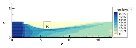
Figure 9.Beamlet crossover limit at upstream plasma density of 1.4×10¹⁷ m-3.(r and z are dimensionless as with the geometric parameters in table 1).
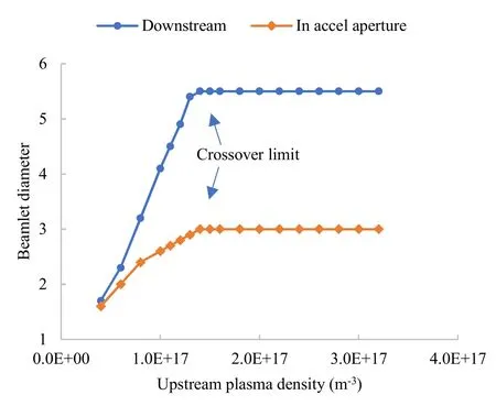
Figure 10.Beamlet diameter represented against the plasma density.(Beamlet diameter is dimensionless as with the geometric parameters in table 1).

Figure 11.Beam and impingement currents represented against the accel grid aperture diameter.(Accel grid aperture diameter is dimensionless as with the geometric parameters in table 1).

Figure 12.Beamlet perveance limit at accel grid aperture diameter of 2.7.(r and z are dimensionless as with the geometric parameters in table 1).
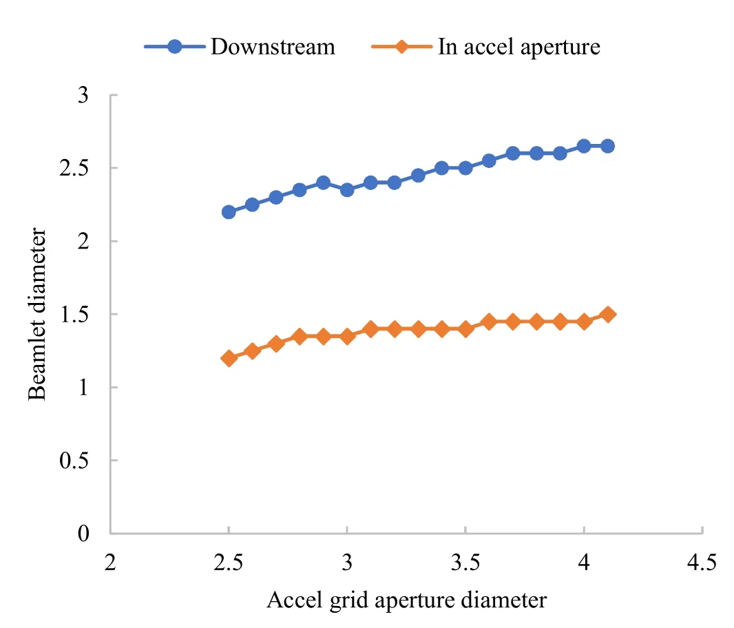
Figure 13.Beamlet diameter represented against the accel grid aperture diameter.(Beamlet diameter and accel grid aperture diameter are dimensionless as with the geometric parameters in table 1).

Figure 14.Saddle point potential and position represented against the accel grid potential.(z coordinate of saddle point is dimensionless).

Figure 15.Saddle point potential and position represented against the plasma density.(z coordinate of saddle point is dimensionless).
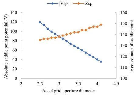
Figure 16.Saddle point potential and position represented against the accel grid aperture diameter.(z coordinate of saddle point is dimensionless).
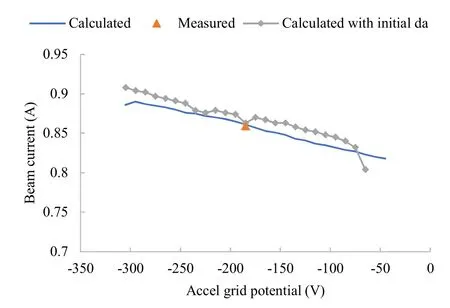
Figure 17.Beam current represented against the accel grid potential as da=3.7.

Figure 18.Saddle point potential represented against the accel grid potential as da=3.7.
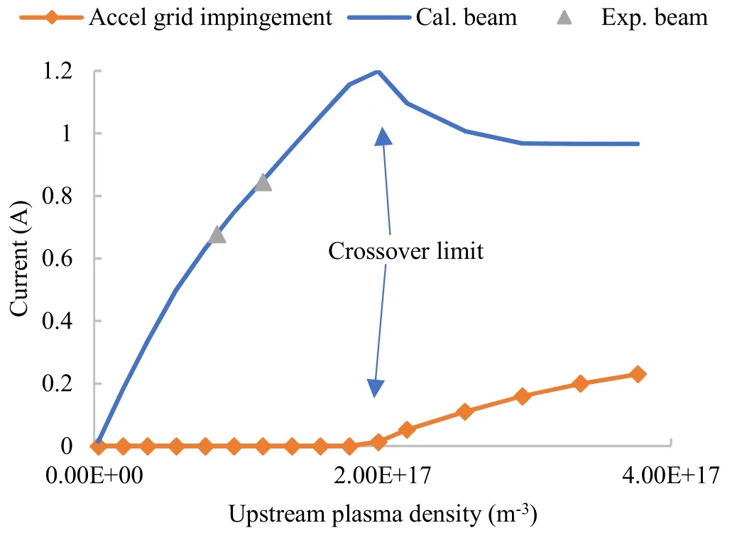
Figure 19.Beam current represented against the upstream plasma density as da=3.7.
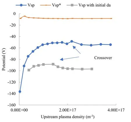
Figure 20.Saddle point potential represented against the upstream plasma density as da=3.7.
(iii)As the accel grid aperture diameter is enlarged by 23%,the critical upstream plasma density of crossover limit increases to 2.0×10¹⁷m-3,corresponding to a beam current of 1.198 A.With this aperture diameter,perveance limit does not occur by increasing the accel grid potential.The enlarged aperture diameter brings loss to the EBSF margin,which is 40 V for rated condition,and 24-48 V for wide-range plasma density.
4.Conclusion
The wide-range beam perveance and saddle point potential characteristics of LIPS-200 ion thruster have been studied with a test-verified ion optics model.The feasible ranges of the beam current and accel grid potential are investigated with both the initial and the eroded states of the accel grid aperture diameter.The results show that the feasible ranges of these parameters with respect to perveance and crossover limits extend as the operating time accumulates.However,the feasible range of accel grid potential should adapt to the reduced EBSF margin as the aperture diameter increases.The feasible ranges determined by the initial condition are:(i)the beam current up to 0.981 A,and(ii)the accel grid potential up to-85 V.A 23%enlargement of the aperture diameter would bring 24 to 48 V of EBSF margin loss depending on the plasma density.
Acknowledgments
Group independent research and development projects(No.YF-ZZYF-2021-132).
猜你喜欢
中学生数理化·八年级物理人教版(2021年12期)2021-12-31
中学生数理化·八年级物理人教版(2020年12期)2021-01-18
下一代英才(酷炫少年)(2019年11期)2020-01-06
中学生数理化·八年级物理人教版(2019年12期)2019-05-21
美与时代·美术学刊(2019年2期)2019-05-08
中学生数理化·八年级物理人教版(2018年12期)2019-01-31
少年漫画(艺术创想)(2018年2期)2018-09-11
东方教育(2018年9期)2018-05-28
东方教育(2018年9期)2018-05-28
东方教育(2018年9期)2018-05-28
 Plasma Science and Technology2022年11期
- Plasma Science and Technology的其它文章
- An equivalent model of discharge instability in the discharge chamber of Kaufman ion thruster
- Discharge and jet characteristics of gliding arc plasma igniter driven by pressure difference
- Investigation of stimulated growth effect using pulsed cold atmospheric plasma treatment on Ganoderma lucidum
- Comparative study of pulsed breakdown processes and mechanisms in self-triggered four-electrode pre-ionized switches
- Nanosecond laser preheating effect on ablation morphology and plasma emission in collinear dual-pulse laser-induced breakdown spectroscopy
- Interaction of an unwetted liquid Li-based capillary porous system with high-density plasma