
Investigation of a facile plasma-driven method for in situ cleaning of metal-based contamination
2023-03-09 05:45SishuWANG王思蜀LiYANG杨黎GuoPU蒲国JianxingLIU刘建星WennaJING荆文娜FujunGOU芶富均ShuweiCHEN陈曙嵬BoCHEN陈波JianjunCHEN陈建军ZongbiaoYE叶宗标andJianjunWEI韦建军
Plasma Science and Technology 2023年1期
Sishu WANG(王思蜀),Li YANG(杨黎),Guo PU(蒲国),Jianxing LIU(刘建星),Wenna JING(荆文娜),Fujun GOU(芶富均),Shuwei CHEN(陈曙嵬),Bo CHEN(陈波),Jianjun CHEN(陈建军),Zongbiao YE(叶宗标),∗ and Jianjun WEI(韦建军),∗
1 Institute of Atomic and Molecular Physics,Sichuan University,Chengdu 610064,People’s Republic of China
2 Key Laboratory of Radiation Physics and Technology,Ministry of Education,Institute of Nuclear Science and Technology,Sichuan University,Chengdu 610064,People’s Republic of China
3 College of Physics,Sichuan University,Chengdu 610064,People’s Republic of China
Abstract Self-cleaning of tin contaminants was realized utilizing a self-driven hydrogen plasma.Cleaning rates of 0.7–6 nm min−1 were achieved for removal of discontinuous tin particles at different powers.The analysis of topography and cross-sectional morphology revealed that the removal of tin particles was achieved through top-down cleaning with hydrogen plasma,where the upper part of spherical tin particles was always more intensely cleaned under the synergistic effect of hydrogen atoms and ions due to the vertical incidence of ions to the substrate during the whole cleaning process.Redeposition of tin atoms caused by physical sputtering and its promotion of the chemical cleaning effect was observed for the first time.Reflectance recovery measurements during cleaning and surface analysis of the substrate after cleaning indicated that nondestructive cleaning with a reflectance loss of less than 1% can be achieved at a relatively low power of 120 W.Plasma-induced substrate damage,such as holes and valleys,reduced the reflectance of the substrate when cleaning was performed at a high power greater than 120 W,so this method should only be considered for application under conditions without substrate exposure.This study provides a comprehensive understanding of the removal of discontinuous tin particles using the in situ self-driven plasma cleaning method,and also provides meaningful guidance for the extension of this method in other potential fields of application.
Keywords:plasma,material,cleaning
1.Introduction
Advanced scientific devices are faced with the problem of contamination of the core components after long-term operation.The accumulation of pollutants will seriously reduce the service life of the components and the operational efficiency of devices[1].Mechanical friction,high-pressure hydraulic power and chemical solvents[2–4]are traditionally used for the removal of contamination.However,these methods may have some shortcomings when cleaning precision parts,such as difficulty in cleaning microscopic-scale pollutants and reduction in the service life of precision components,due to their relatively rough operating procedures.Mirrors utilized for optical diagnosis and collection are the most representative of the precision components that need cleaning.This is because the presence of microscopic pollutants can cause a significant drop in mirror reflectance.Owing to the strict requirements of cleaning technology for microscopic-scale pollutants,a highly selective cleaning method at the atomic scale is proposed,which removes contaminants through chemical reactions between contaminants and radicals generated by a hot tungsten filament[5].However,due to its low efficiency and potential damage to the mechanical properties of materials caused by high temperature,limitations of the atomic cleaning method have gradually become apparent,especially in the area of lithography[6].The method of low-temperature plasma cleaning has great application potential and has attracted increasing attention because of its higher degree of ionization and physical sputtering-assisted chemical reaction,giving a much higher cleaning rate than the atomic cleaning method[7].
Capacitively coupled plasma(CCP)and inductively coupled plasma(ICP)are commonly utilized for generating plasmas,typically through capacitively coupled discharge and inductively coupled discharge.In the field of fusion,the first mirrors(FMs)used for optical diagnosis[8]are inevitably contaminated by impurities derived from plasma-facing materials[9],and the cleaning of FMs has been carried out extensively[10–12].Ushakovet alutilized CCP to clean the metal contaminants deposited on the FMs and effectively restored their reflectance[13].Multilayer mirrors(MLMs)applied to collect extreme ultraviolet light also face the serious problem of reflectance reduction caused by deposition of tin,which comes from a light source in a laser-produced plasma(LPP)lithography machine[14,15].Shinet al[16]and Sporreet al[17]utilized an ICP source and radiofrequency(RF)-driven helicon plasma source,respectively,to study the cleaning effect of hydrogen plasma on tin contaminants.In the accelerator field,a method based on ICP cleaning was developed by our laboratory to clean hydrocarbon contamination on the internal surface of the superconducting niobium cavity in the accelerator to improve the work function and weaken the secondary electron emission[18].Due to the structural complexity of the plasma generator and the time and spatial inhomogeneity of plasma under the action of an electromagnetic field,the composition of plasma and its corresponding proportions are evolving during transmission,making it difficult to achieve unity of operability and cleaning effect.Elget al[19]proposed a collector-driven plasma cleaning method in which the MLMs themselves were used as electrodes for plasma generation and preliminary cleaning of uniformly dense tin films on the surface of virtual MLMs[20].However,this method has certain limitations due to the discrete distribution of plasma between MLMs and the grounded chamber,which causes high power consumption and potential damage to ambient optical components.In addition,the cleaning process and mechanism at the micro level have not been revealed.This researchers work deserves further optimization and in-depth study.Some of the previous work concerned plasma removal of metal pollutants.The cleaning mechanism of hydrogen plasma on metal impurities,namely copper(Cu),iron(Fe)and potassium(K),on a Si substrate has been revealed[21].Cu,K and Fe impurity atoms which coexist with the chemical and/or native oxides on the Si wafer surface are eliminated together when the oxides are removed by hydrogen plasma[22].However,this chemical mechanical polishing method is different from the mechanism of chemical reaction cleaning of tin by hydrogen plasma.Therefore,the chemical cleaning mechanism of tin by hydrogen plasma needs to be elucidated.Combined with the current status of research in the field of lithography and laboratory conditions,we use an improved self-cleaning device to clean metal pollutants closer to real operating conditions.The role of each component during plasma cleaning was explored to make a reasonable evaluation of the feasibility of this cleaning method.
In this work,a facile self-driven plasma cleaning method was developed to nondestructively remove superficial contaminants with a discontinuous granular-structure on smooth silicon(Si)in situ.Meanwhile,island-like particles were deposited and cleaned for the first time to simulate the typical contaminants existing in practical operating conditions.A comprehensive understanding of plasma characteristics on the discharge electrodes was obtained through the effect of different kinds of plasma on tin,allowing effective analysis of the cleaning mechanism.This study promotes the development of anin situself-driven plasma cleaning method and provides a reference for its potential application in other fields.
2.Experimental details
2.1.Coating preparation
Pollutant deposition on FMs or MLMs is realized using atoms aggregated into particles,which means that the pollutants are nonuniform and discontinuous.Elget alpointed out that it was difficult to remove the remaining discontinuous tin islands on the surface of Si wafers as cleaning progressed[23].Therefore,discontinuous contaminants with particulate morphology were deposited to study the cleaning process and mechanism.Evaporative coating was obtained in our sample preparation process.The evaporation experiment was carried out in a tube furnace with a single temperature zone and background pressure of 10−5Pa.A tin-filled crucible was placed in the constant-temperature zone with an evaporation temperature of 1100 °C,and argon gas with a flow rate of 150 sccm was used to transport tin vapor.The Si wafer was placed 70 cm away from the crucible along the direction of gas flow,and the deposition temperature was fixed at 180°C.A schematic diagram of the evaporation device is shown in figure 1.The size of the tin particles and thickness of the tincoated layer could be controlled by changing the deposition time.In this work,the thickness of the tin-coated layer was approximately 200 nm over a deposition time of 15 min.
2.2.Experimental device
Generally,high-flux hydrogen ions with an incident energy below 50 eV are required to clean tin contaminants on MLMs[24].Thus,a CCP system that generates low-energy,highflux hydrogen ions was developed to investigate the cleaning of tin particles deposited on the Si surface.The system utilizes the discharge electrode to drive the hydrogen plasma,which allows plasma creation at the desired location in the absence of any delivery system[25–27]and achieves the purpose of online cleaning without downtime.
The cleaning experiment was carried out on an independently developed self-driven plasma cleaning platform that used a stainless steel round platform with a diameter of 25 mm as the discharge electrode and a grounded outer metal ring to generate plasma.The specific structure of the selfdriven plasma cleaning platform is shown in figure 2(a).Here the discharge electrode is connected to the SY-500 RF power supply(13.56 MHz)through a copper rod,and the entire structure is well shielded by polytetrafluoroethylene(PTFE).The background pressure in the vacuum chamber is 10−4Pa.During plasma cleaning,a hydrogen flow rate of 200 sccm with a working pressure of 180 Pa and power of 10–200 W were used.A physical image of the self-driving discharge is displayed in figure 2(b).
To measure the plasma parameters and monitor the temperature of the discharge electrode in real time during cleaning,a Langmuir RF compensation double probe and a thermocouple can providein situdiagnostics situated in the self-driven plasma cleaning platform.In this work,variations in plasma parameters(electron densityneand electron temperatureTe)with power as well as their spatial distribution on the discharge electrode surface were diagnosed.
2.3.Characterization techniques
To characterize the cleaning rate,half of the tin-coated sample was masked with a Si wafer to form a cleaning step during cleaning.To characterize the spatial distribution of the cleaning rate,a long strip of tin-coated Si wafer was used,and five equally spaced positions along the radius of the discharge electrode were selected for testing.A three-dimensional(3D)optical surface profilometer(Super View W1)was applied to measure the variation in surface roughness during cleaning and the height of steps was formed after cleaning.Reflectance in the sample was measured by a UV–Vis spectrophotometer(UV;760CRT).The surface morphology and cross-sectional morphology of the samples was investigated by scanning electron microscopy(SEM;FEI Inspect F50).Topography of samples after cleaning was obtained by atomic force microscopy(AFM;Park XE7).
3.Results and discussion
3.1.Diagnosis of plasma parameters
In the self-driven plasma cleaning platform,the Langmuir RF compensation double probe was used to measure the plasma parameters.The averageneandTeof the hydrogen plasma at different powers were measured at the center of the discharge electrode,and the results are shown in figure 3.It can be seen thatneincreases with increasing power whileTedecreases with increasing power.At higher RF power,a stronger electric field will be generated due to the increase in voltage between the discharge electrode and the grounding electrode,where extranuclear electrons are more likely to overcome the attraction of the nucleus and become free electrons.The decrease inTewith increasing power is related to the variation in the mean free path of electrons.At the same degree of ionization,the mean free path of electrons can be written as
whereleis the mean free path of electrons,dis the effective molecular diameter andn0is the initial total particle density.Equation(1)shows that the mean free path is inversely proportional to the total particle density.An increase in power will increase the degree of ionization of the plasma andne,resulting in a decreased mean free path.Since the mean free path is shorter,the distance at which the electrons are accelerated by the electric field becomes shorter,finally leading to a lower average kinetic energy andTe[28].
The spatial distribution of plasma parameters on the surface of the discharge electrode was measured at 120 W,as shown in figure 4.Figure 4(a)shows thatneon the surface of the discharge electrode is highest at the center and decreases gradually toward the edge,which is basically in line with the characteristics of a Gaussian distribution.The variation ofTeis opposite to that ofne,showing a trend of lowerTeat the center and higherTetoward the edge.The reason for the difference in the variation law ofTeandnehas been explained above,and is related to the mean free path of electrons as shown in formula(1).Although there is spatial inhomogeneity inTeandne,they are of the same order of magnitude on the discharge electrode surface,and the samples are placed in the center of the discharge electrode during cleaning to minimize the effect of nonuniformity.As shown in figure 4,neandTeat the center of the discharge electrode are 4.6×10¹⁶m−3and 1.3 eV,respectively.
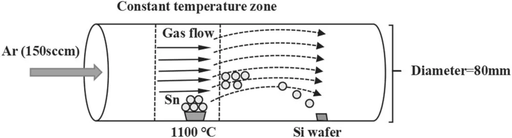
Figure 1.Schematic diagram of the experimental evaporation apparatus.
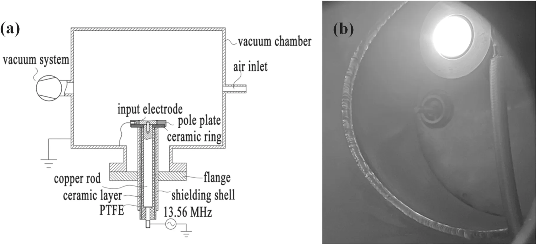
Figure 2.Schematic diagram of the self-driven plasma cleaning platform(a)and physical image of the self-driving discharge during cleaning(b).
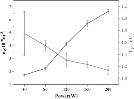
Figure 3.The average ne and Te of hydrogen plasma at the center of the discharge electrode at different powers.
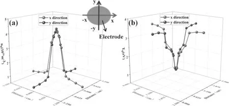
Figure 4.Spatial distribution of ne(a)and Te(b)of the self-driven hydrogen plasma.
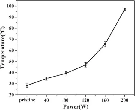
Figure 5.The temperature at different powers.
With regard to the metal components,an increase in temperature tends to reduce the elastic modulus and hardness and increase the elongation,creep and relaxation,which can seriously affect the function of the components.Accordingly,it is necessary to monitor the temperature of the discharge electrode in real time during the cleaning process.The change in temperature of the discharge electrode with power measured by the thermocouple is shown in figure 5.The temperature of the discharge electrode presents an increasing tendency with increasing power but never exceeds 100 °C,even at a a relatively high power of 200 W.The properties of metal components will not change in such a low temperature range[29],indicating that the cleaning conditions we plan to adopt are reasonable.
3.2.Self-driven hydrogen plasma cleaning
3.2.1.Investigation of the cleaning rate at different input powers.To effectively measure the cleaned thickness,five contour scans and cleaning rate calculations were performed after each cleaning by a 3D optical surface profilometer when the samples were incompletely cleaned.The results for the cleaning rates are expressed by the average value and the standard deviation.
The rates of removal of tin in the center of the discharge electrode with input power ranging from 10 to 200 W are shown in figure 6(a).As shown in this figure,the removal rate of tin particles increases gradually with increasing input power.This makes sense becauseneincreases with increasing input power,as shown in figure 3(a),as do the ion density(the plasma is electrically neutral,soneis equal to the ion density)and hydrogen radicals[30].A highernewill produce a higher ion flux,which accelerates the cleaning reactions.Another important factor in the cleaning process is the number of hydrogen radicals required to clean a tin atom[31].Relevant literature has pointed out that 1×10⁵hydrogen radicals are required for each tin atom to be cleaned on average[23].This means that a larger number of tin atoms can be cleaned with a larger number of hydrogen radicals.The synergistic effect of the ion flux and hydrogen radicals can well explain the trend of the tin removal rate with power.After piecewise fitting of the cleaning rate curve,it is observed that the two curves intersect at point P,as shown in figure 6(a).The results show that the change in cleaning rate with power after point P(k2)is 3.8 times that before point P(k1).The reason for this phenomenon will be described in detail in the following.
The rate of removal of tin along the radius of the discharge electrode at different powers is shown in figure 6(b).The rate of removal of tin gradually increases from the edge of the discharge electrode to its center.This phenomenon is in accordance with the spatial distribution ofne,which is the highest at the center and decreases gradually toward the edge,as shown in figure 4(a).The spatial distribution of the tin removal rate is the same asnebut opposite toTe,as shown in figure 4,indicating that the thermal effect of electrons has little effect on the cleaning rate.
During a capacitively coupled discharge,plasma can be generated by applying RF excitation directly to the powered electrode,leading to the formation of a negative DC potential,the self-bias(VDC),on the powered electrode.The DC voltage drop across the powered electrode sheath is defined byVs=Vp−VDC,whereVpstands for the positive plasma potential.The plasma potential was measured by a Langmuir single probe,and the results showed that the plasma potential was no more than 0.1 V at 200 W,which is negligible compared with the self-bias.The maximum ion energy(Eion,in eV)hitting the powered electrode is determined by the sheath potential drop,for exampleVs[32].Under our experimental conditions,Eionis less than 80 eV and 110 eV at 80 W and 120 W,respectively.Physical sputtering occurs at 120 W,which is higher than the sputtering threshold of hydrogen ions on tin(104.1 eV)[33];this indicates that physical sputtering starts at 120 W.The slope difference before and after 120 W in figure 6(a)and the cleaning rate at more than 120 W in figure 6(b)are significantly higher than the cleaning rate at less than 120 W,and are both caused by physical sputtering.
From what has been discussed above,the power corresponding to the sputtering threshold is near point P(the intersection of the first three points and the last three points after fitting,approximately 108 W).The hydrogen ion energy at 108 W is approximately 105 eV,and the initiation of physical sputtering at this ionic energy is in good agreement with the threshold of hydrogen ion to tin sputtering in the literature.
According to the above data,it can be concluded that chemical reaction cleaning plays a major role in tin cleaning before the sputtering threshold,but the cleaning rate is an order of magnitude higher than that of pure atomic hydrogen[7]because ions also play a role in accelerating cleaning when physical sputtering does not occur.Above the sputtering threshold,chemical reaction cleaning and physical sputtering have synergistic effects;at this time,physical sputtering of ions is dominant,greatly speeding up the cleaning rate.
3.2.2.Morphological change of tin particles during the cleaning process.To understand the process of cleaning of tin pollutants by hydrogen plasma,evolution of the surface morphology during cleaning was characterized.Figure 7 presents the change in surface morphology of tin particles with cleaning time.Spherical tin particles of various sizes were present on the surface of the Si substrate before cleaning,as shown in figure 7(a).After 10 min of cleaning,the distribution density of small tin particles decreases and cleaning traces appear on top of medium to large particles,as shown in figure 7(b).After 20 min of cleaning,nearly no small tin particles remained,and the cleaning traces on medium to large particles became more obvious,with deep grooves as shown in figure 7(c).Afterwards,with increasing cleaning time,the depth of the grooves on large tin particles is further increased,and the diameter of the particles decreases,as shown in figure 7(d).When the cleaning time reached 40 min,no spherical particles can be seen and only small fragments of particles produced by cleaning remain,as shown in figure 7(e).After 50 min cleaning,the size of tin particle fragments is further reduced,leaving only slight traces of tin contamination on the surface of the Si wafer,as shown in figure 7(f).When the cleaning time reaches 60 min,the tin particles have been removed completely,leaving a flat surface with the same surface morphology as the original Si wafer,as shown in figures 7(g)and(h).
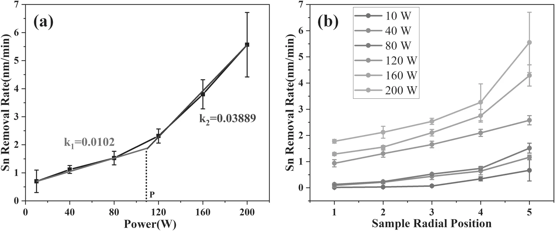
Figure 6.Change in tin removal rate with power in the center of the discharge electrode(a)and along the radius of the discharge electrode(b).
Through the above analysis,tin particles of various sizes were removed through top-down cleaning.During the initial stage of cleaning,small tin particles should be also removed through top-down cleaning,but this required less time due to their small size given the same removal rate,resulting in the preferential removal of small particles.These results show the effectiveness of self-driven hydrogen plasma cleaning for removing discontinuous tin particles of various sizes.
To further study the tin cleaning process,the surface roughness of tin-coated Si samples after different times of hydrogen plasma cleaning at 120 W was measured by a 3D optical surface profilometer.The results are shown in figure 8.Figure 8(a)displays the topography of the tin-coated sample before and after plasma cleaning for 30 and 60 min,respectively,and the topography of the Si substrate is also given for comparison.The change in roughness with cleaning time is shown in figure 8(b),from which it can be seen that both arithmetic mean height(Sa)and the root mean square height(Sq)decrease gradually with increasing cleaning time,caused by the progressive removal of tin particles.After 60 min of cleaning,the surface roughness of the sample is reduced to a fairly low level close to that of the Si substrate(Sq=1 nm,Sa=1 nm).This can be also seen from the similar topography of the cleaned sample surface and the original Si surface,as shown in figure 8(a),demonstrating that the surface contaminants have been almost completely removed,leaving the Si substrate exposed.
To further understand the process of top-down cleaning,cross-sectional analysis was carried out on the tin-coated sample after cleaning for 20 min,40 min and 60 min at 120 W.The results are shown in figure 9.The tin particles are completely spherical in shape with various sizes before cleaning,as shown in figure 9(a).After 20 min cleaning the upper part of the tin particles was clearly cleaned with obvious cleaning traces while the lower part basically retained a spherical shape,as shown in figure 9(b).After 40 min cleaning,the spherical tin particles were cleaned to less than half of their original volume,leaving only the bottom of the spherical structure faintly visible,as shown in figure 9(c).This further proves that the cleaning of tin occurred by a topdown method.Figures 9(b)and(c)also show that the cleaning traces on tin particles are uneven;this is caused by the unfixed ion bombardment angle and free radical binding sites during the cleaning process.After 60 min cleaning,no remains of tin particle are visible,leaving only the flat surface of the Si substrate,as shown in figure 9(d),indicating the complete removal of tin contaminants.
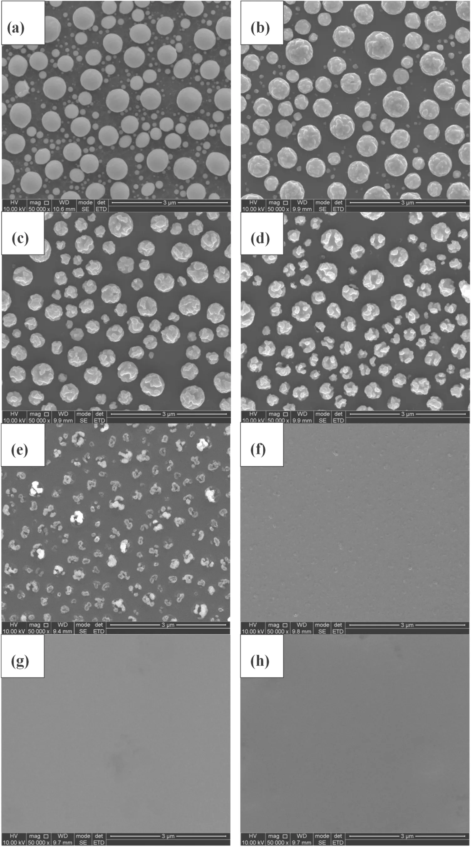
Figure 7.SEM images of tin-coated Si wafers before(a)and after((b)–(g))different cleaning times:(b)10,(c)20,(d)30,(e)40,(f)50 and(g)60 min.(h)The original Si wafer.
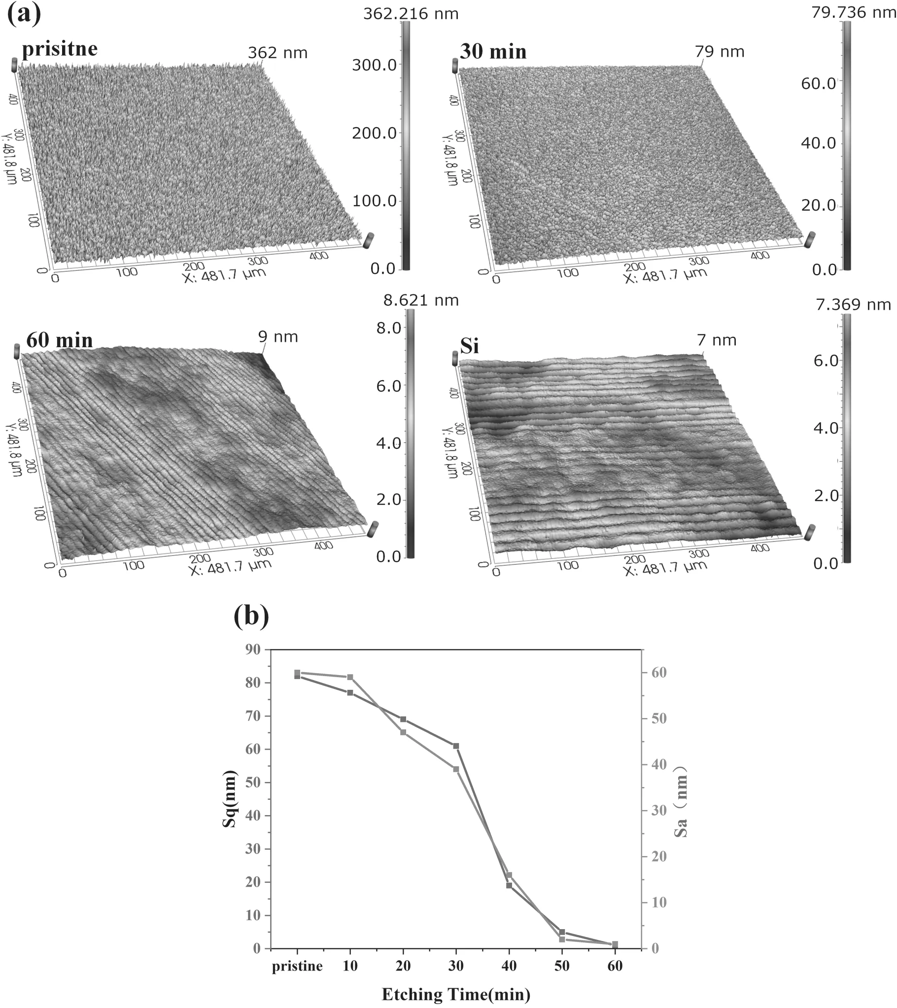
Figure 8.(a)3D topography of the tin-coated sample before and after plasma cleaning at 120 W for 30 and 60 min and the topography of the Si substrate.(b)The evolution of Sq and Sa of tin-coated samples with cleaning time.
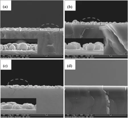
Figure 9.Cross-sectional morphology of the tin-coated sample before(a)and after cleaning for 20 min(b),40 min(c)and 60 min(d).
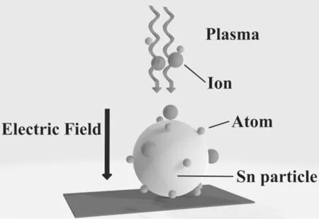
Figure 10.Schematic diagram of a spherical model for tin particle cleaning.
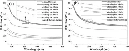
Figure 11.Change in reflectance with cleaning time at 120 W(a)and 200 W(b).
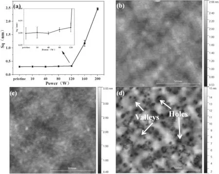
Figure 12.(a)Roughness change of Si wafers after 5 h of cleaning at different powers.Topography of the original Si wafer(b)and of the Si wafer after being cleaned for 5 h at 120 W(c)and 200 W(d).
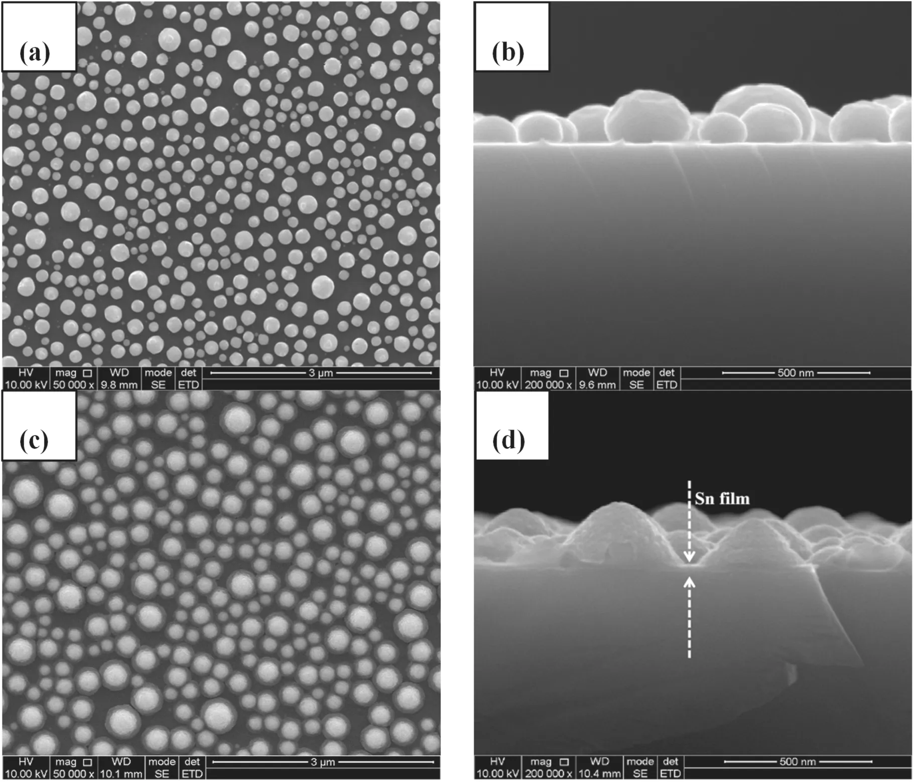
Figure 13.Surface((a),(c))and cross-sectional((b),(d))morphology of a tin-coated sample before((a),(b))and after((c),(d))cleaning by He plasma for 1 h.
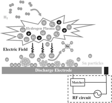
Figure 14.Diagram of the reaction principle of tin cleaning.
It can also be observed from the cross-sectional view that the spherical structure of the upper part of the tin particles changes obviously during the cleaning process,while the bottom part maintains the original spherical structure for more than 40 min.A spherical model of particle cleaning was built to illustrate the cleaning process,as shown in figure 10.The neutral hydrogen atoms are uniformly distributed on the surface of the discharge electrode and are unaffected by the electric field.During cleaning,the spherical tin particles are surrounded by hydrogen atoms.However,the ions are incident perpendicular to the upper surface of the spherical tin particles in the presence of an electric field,making the upper part of the spherical structure more susceptible to the ion flux.Therefore,hydrogen atoms clean the upper part of tin particles more intensely under the synergistic effect of ions.Due to the special structure of a sphere,the ion flux received by the lower part of the spherical tin particles is relatively low and the energy of the incident ions may be reduced due to their nonvertical direction.Therefore,the cleaning effect of hydrogen atoms on the bottom of the spherical structure is greatly weakened in the absence of the synergistic effect of ions,resulting in a slow morphological change,which also indicates that ions play a key role in cleaning.
3.2.3.Measurement of reflectance after cleaning.As the most important property of optical devices,the reflectance of the samples was measured to characterize the effect of selfdriven hydrogen plasma cleaning.To characterize the variation in reflectance during the cleaning process,the reflectance of the samples cleaned for different times from 10 to 60 min was measured.A power of 120 W with a medium cleaning rate and 200 W with a high cleaning rate were selected for testing.A UV spectrophotometer was used for reflectance measurements in the wavelength range of 365–800 nm.
Reflectance is the percentage of radiant energy reflected by an object compared with the total radiant energy.The reflectance mainly depends on the nature of the object itself(surface condition).According to Bachmann’s reflection probability model[34],the reflectanceRis given by
whereR0is the reflectance of an ideal smooth surface of the same material andris the root mean square roughness(Sq).From equation(2),it can be seen that the reflectance is inversely proportional to the roughness;that is,a decrease in roughness will increase the reflectance.This model does not consider the interaction between the light and the surface,so there will be a certain error compared with the actual value,but it can characterize the trend in reflectance variation caused by the roughness change.
The variations in reflectance with cleaning time at different powers of 120 W and 200 W are shown in figure 11.Equation(2)can effectively explain the negative correlation between the roughness in figure 8(b)and the reflectance in figure 11.The reflectance of the tin-coated Si sample gradually increases with increasing cleaning time at a power of 120 W,as shown in figure 11(a).After 60 min cleaning,the reflectance was restored to the level of the original Si wafer,with a reflectance loss of less than 1%;this can be seen from the approximate overlap of the dark gray line and the red line in figure 11(a).Nevertheless,when cleaning was performed at 200 W,the reflectance of the tin-coated Si sample could not be restored to the level of the original Si wafer regardless of how long the cleaning time was prolonged,as shown in figure 11(b).After 30 min cleaning,the reflectance recovered to a maximum value of approximately 97% of that of the original Si wafer and then decreased gradually with increasing cleaning time.The difference in reflectance change with cleaning time at different powers is understandable because a stronger electric field will be generated due to the increase in voltage between the discharge electrode and the ground electrode at higher RF power,as mentioned in section 3.1.The enhanced electric field can accelerate ions to higher energies,and the high-energy ions will produce sputtering and implantation effects on the Si substrate while the tin is cleaned,causing irreversible damage.As mentioned in section 3.2.1,physical sputtering starts at 120 W,and a working power of 200 W will definitely bring about stronger sputtering.Therefore,when cleaned at 200 W,the decrease in reflectance after reaching the maximum value is due to the damage to the surface of the Si wafer caused by excessive cleaning and high-energy ion bombardment.
Through the above analysis,it can be seen that selfdriven hydrogen plasma cleaning can effectively remove discontinuous particles of tin on Si wafers.This method removes tin contaminants through chemical reaction and can be extended to the removal of other contaminants by adjusting the type of discharge gas,for example the removal of contaminants from molybdenum(Mo)or rhodium(Rh)mirrors in fusion devices[35].
3.2.4.Damage evaluation.The effectiveness of thein situself-driven hydrogen plasma cleaning method in removing tin contaminants from the Si surface has been demonstrated,but the physical sputtering effect of ions is worth studying sinceEionunder high power(>120 W)can exceed the sputtering threshold of the Si substrate(104.1 eV),resulting in a decrease in reflectance of the substrate after excessive cleaning,as described in sections 3.2.1 and 3.2.3.Additionally,the tin contaminants deposited on the surface of the devices are not uniformly distributed,and part of the device will inevitably be directly exposed to plasma,which also increases the risk of damage to the device caused by physical sputtering.Therefore,it is crucial to investigate the damage to the sample surface after plasma cleaning at different powers to assess whether exposure to plasma would pose a threat to the Si surface.
To evaluate the damage,the Si wafers were cleaned for 5 h at different powers and the corresponding surface roughness was measured by AFM over an area of 1 μm ×1 μm.The results are shown in figure 12(a).Almost no damage occurs on the Si wafer,with a roughness change of less than 0.02 nm when cleaning occurs below 120 W.The subtle influence of low-power cleaning on the surface of Si wafers can be also seen from the similar topography of the original Si wafer and the wafer cleaned for 5 h,as shown in figures 12(b)and(c).When the cleaning power is higher than 120 W,the surface roughness increases by 293% and 726% at 160 and 200 W,respectively.As mentioned in sections 3.2.1 and 3.2.3,the bombardment of energetic ions accelerated by an electric field at high power can cause damage to the surface of the Si wafer,resulting in a reduction in reflectance.The holes and valleys formed on the surface of the Si wafer are direct evidence of damage after 5 h of plasma cleaning at 200 W,as shown in figure 12(d).The Netherlands Organization for Applied Scientific Research(TNO)proposed that the cleaning power for optical devices in lithography systems should not exceed 50 W over a long time to protect the optical device from being damaged by energetic ions[36].This explains why the surface roughness did not change when we cleaned the sample at 40 W and below,as shown in figure 12(a).
3.3.Discussion of the cleaning mechanism
3.3.1.Physical sputtering.As described above in section 3.1,physical sputtering by low-energy ions can improve the cleaning efficiency because continuous sputtering weakens the chemical bonds between tin atoms.Additionally,although the plasma density increases as the power increases,it is always of the same order of magnitude within 200 W,as shown in figure 3(a).However,the slope(k)of the tin removal rate exhibits an obvious discrepancy under the cleaning power before and after point P.The slope of the tin removal rate after point P(k2)is approximately 3.8 times that before point P(k1).The reason behind this phenomenon is that the sputtering threshold is near point P,resulting in sputtering out of tin atoms and an improved cleaning rate assisted by physical sputtering.To verify the above conjecture,the physical sputtering mechanism during the cleaning process will be systematically studied in the following.
Considering that it is impossible to study the physical sputtering of tin by hydrogen plasma since chemical reaction of tin with hydrogen atoms is inevitable,helium(He)is chosen as a substitute for hydrogen to study the effect of physical sputtering because it has the closest atomic number to hydrogen and does not chemically react with tin.
The tin-coated Si wafer was cleaned at an input power of 120 W and working pressure of 180 Pa;the cleaning time was 1 h.The sputtering threshold of He plasma to tin is 29.6 eV[31],where the bias voltage is 110 V and the ion energy is less than 110 eV.It is obvious that physical sputtering has taken place under such conditions.Surface and cross-sectional morphologies were examined by SEM before and after He plasma cleaning,as shown in figure 13.Before cleaning,the spherical structure of tin particles is clearly seen in the surface and cross-sectional images,as presented in figures 13(a)and(b).After 1 h of He plasma cleaning,the tin particles show no noticeable change in size from the surface morphology,but a ring-like structure appears around the cleaned tin particles,as displayed in figure 13(c).From the cross-sectional morphology in figure 13(d),it can be seen that the spherical tin particles become conical and thin films are formed on the Si substrate between the gaps in the conical particles after cleaning.The reason behind this phenomenon is that the physical bombardment of energetic ions in He plasma leads to the rupture of chemical bonds between tin atoms in the tin particles,which results in sputtering out of tin atoms from the tin particles.The sputtered tin atoms cannot be removed through chemical reaction,so redeposition of tin atoms occurs.Some of the sputtered tin atoms are redeposited on the tin particles to form a conical structure,and the others are redeposited between the gaps in the conical particles to form ring-like thin films surrounding the cleaned tin particles.
The discovery of tin atoms redeposited by physical sputtering of tin particles is of great significance because the redeposition of tin atoms increases the contact area between tin atoms and hydrogen radicals under the effect of ions,thus increasing the chemical cleaning rate.In addition,the thickness of the deposited tin film is small,so it can be preferentially removed during chemical cleaning,just as the small tin particles are preferentially removed in figure 7.This discovery also suggests an alternative method for removing tin pollutants,namely mixing a certain proportion of argon or helium in hydrogen to make physical sputtering more likely to occur and improve the cleaning efficiency under the synergistic effect of physical sputtering.High-energy ioninduced physical sputtering should be avoided in the cleaning of MLMs in a lithography system;however,substrate sputtering is to some extent necessary in the cleaning of FMs in fusion devices since contaminants might be implanted within the first tens of nanometers of the mirror material[37].To extend thisin situself-driven hydrogen plasma cleaning method to other applications,study of the physical sputtering effect is essential.Experiments to further verify the effect of physical sputtering on chemical cleaning are being planned,and will be the focus of subsequent research.
3.3.2.A comprehensive analysis of the cleaning process.According to the above analysis and discussion,tin pollutants are mainly removed by chemical cleaning,and a schematic diagram of the cleaning principle is shown in figure 14.Hydrogen radicals generated by the ionization of hydrogen are used as reactants during cleaning and combine with tin atoms to form volatile SnH4,which can be pumped out from the chamber through a vacuum system to achieve the cleaning effect.The corresponding chemical reaction formula is as follows:
The cleaning process begins with the generation of dense,chemically active hydrogen atoms and ions due to the high ionization rate of plasma cleaning technology.In the cleaning process,chemical cleaning is dominant at powers lower than 108 W,and ions promote the occurrence of chemical reactions.When the power is higher than 108 W,ion sputtering is dominant even though the co-existence of chemical reaction cleaning and physical sputtering greatly accelerates the cleaning rate.Physical sputtering of plasma leads to redeposition of tin atoms,which can increase the area of contact between the reactants and thus speed up chemical cleaning,as described in section 3.3.1.Physical bombardment of ions can also result in the formation of dangling bonds in the structure of tin,which are active Sn*sites that can bind to hydrogen radicals.During this step,the impinging ions can enhance the reaction by delivering their kinetic energy to the surface;this is used as surface diffusion activation energy as well as desorption activation energy[38].As the direction of ion injection is perpendicular to the sample surface along the electric field,the upper surface of tin particles is exposed to a greater ion flux,resulting in faster cleaning of the upper surface and top-down cleaning of the whole particles.Ions certainly play a critical role in the cleaning process,but a high-energy ion will damage the surface of the optical device and cause irreversible effects,as shown in figure 12.Therefore,it is very significant to improve the self-driven hydrogen plasma cleaning method and to provide high-flux ions and high-density radicals while keeping the ion energy lower than the value that causes damage to the substrate.
4.Conclusion
In this work,we utilized a self-driven plasma cleaning method to effectively remove superficial discontinuous granular contaminants from smooth siliconin situand restore the reflectance of the substrate.Meanwhile,the influence of ions and atoms in hydrogen plasma on tin pollutants was analyzed.It has been proven that self-driven plasma cleaning can effectively remove tin contaminants with cleaning rates of 0.7–6 nm min−1at different powers and restore the reflectance of the sample with a reflectance loss of less than 1%.Analysis of the surface and cross-sectional morphology revealed that the tin particles were cleaned top-down,with the morphology changing from spherical to hemispherical to small fragments and gradually decreasing roughness with increasing cleaning time.The reason for top-down cleaning was that the ions were vertically incident on the upper surface of tin particles along the electric field,and their energy was transferred to tin particles to promote the breaking of chemical bonds on the surface,thus providing reactive sites and accelerating the cleaning rate on the upper part of the tin particles.The auxiliary effect of atom redeposition induced by physical sputtering on chemical cleaning has also been preliminarily studied,but confirmation is needed.Although the self-driven plasma cleaning method had a good effect on the removal of discontinuous large tin particles,irreversible damage,such as holes and valleys,still appeared on the substrate after high-power and long-term cleaning.This study is of great significance for understanding the cleaning mechanism of tin contaminants and has reference value for the extension of thisin situself-driven cleaning method to other applications.
Acknowledgments
This work has been funded by National Key,Development Program of China(No.2017YFE0301305-KYWX-002),Sichuan Science and Technology Program(No.2021YFSY0015)and Institutional Research Fund from Sichuan University(No.2020SCUNL211).
ORCID iDs
猜你喜欢
环球时报(2022-08-02)2022-08-02
浙江人大(2022年4期)2022-04-28
Chinese Physics B(2022年3期)2022-03-12
作文·小学低年级(2021年6期)2021-11-02
Plasma Science and Technology(2021年2期)2021-02-27
孩子(2021年2期)2021-02-25
江苏教育·书法教育(2020年10期)2020-09-10
考试与评价·高二版(2020年6期)2020-09-10
当代人(2020年4期)2020-05-08
中华魂(2017年8期)2017-11-22
 Plasma Science and Technology2023年1期
- Plasma Science and Technology的其它文章
- Development of miniaturized SAF-LIBS with high repetition rate acousto-optic gating for quantitative analysis
- Rotor performance enhancement by alternating current dielectric barrier discharge plasma actuation
- A nanoparticle formation model considering layered motion based on an electrical explosion experiment with Al wires
- Focused electron beam transport through a long narrow metal tube at elevated pressures in the forevacuum range
- A study of the influence of different grid structures on plasma characteristics in the discharge chamber of an ion thruster
- High-resolution x-ray monochromatic imaging for laser plasma diagnostics based on toroidal crystal