
Experimental investigation of dynamic stall flow control using a microsecond-pulsed plasma actuator
2023-03-15 00:54ZeyangXU徐泽阳BinWU武斌ChaoGAO高超NaWANG王娜andTianhaoJIA贾天昊
Plasma Science and Technology 2023年3期
Zeyang XU(徐泽阳),Bin WU(武斌),*,Chao GAO(高超),Na WANG(王娜) and Tianhao JIA (贾天昊)
1 School of Aeronautics,Northwestern Polytechnical University,Xi’an 710072,People’s Republic of China
2 Xi’an Aeronautical Institute, Xi’an 710072, People’s Republic of China
Abstract To alleviate the performance deterioration caused by dynamic stall of a wind turbine airfoil,the flow control by a microsecond-pulsed dielectric barrier discharge (MP-DBD) actuator on the dynamic stall of a periodically pitching NACA0012 airfoil was investigated experimentally.Unsteady pressure measurements with high temporal accuracy were employed in this study,and the unsteady characteristics of the boundary layer were investigated by wavelet packet analysis and the moving root mean square method based on the acquired pressure.The experimental Mach number was 0.2, and the chord-based Reynolds number was 870 000.The dimensionless actuation frequencies F+were chosen to be 0.5,1,2,and 3,respectively.For the light dynamic regime,the MP-DBD plasma actuator plays the role of suppressing flow separation from the trial edge and accelerating the flow reattachment due to the high-momentum freestream flow being entrained into the boundary layer.Meanwhile, actuation effects were promoted with the increasing dimensionless actuation frequency F+.The control effects of the deep dynamic stall were to delay the onset and reduce the strength of the dynamic stall vortex due to the accumulating vorticity near the leading edge being removed by the induced coherent vortex structures.The laminar fluctuation and Kelvin-Helmholtz (K-H) instabilities of transition and relaminarization were also mitigated by the MP-DBD actuation,and the alleviated K-H rolls led to the delay of the transition onset and earlier laminar reattachment, which improved the hysteresis effect of the dynamic stall.For the controlled cases of F+=2, and F+=3, the laminar fluctuation was replaced by relatively low frequency band disturbances corresponding to the harmonic responses of the MP-DBD actuation frequency.
Keywords: microsecond-pulsed plasma actuator, dielectric barrier discharge, flow control,dynamic stall, wind turbine, wind tunnel experiment
1.Introduction
Due to the excessive consumption of fossil fuels, the global environment has been deteriorating for decades.To mitigate this negative impact, sustainable alternative clean resources have been a hot topic of research in recent years,one of which is wind energy, which has been greatly promoted worldwide because of its advantages of cleanliness,wide distribution,and relatively low construction cost.As the most common wind energy capture device, the performances of wind turbines,including horizontal and vertical axis wind turbines, are critical to the efficiency of energy conversion.However, as the rotor diameter grows, so do the unsteadiness and nonlinearity of the turbine blades, which results in the deterioration of aerodynamic performance of wind turbine airfoils, especially the impact from dynamic stall caused by yaw motion, free stream turbulence, impinging gusts, and tower shadow [1-3].
Airfoil dynamic stall is a complex phenomenon of unsteady separation of the boundary layer, as the angle of attack(AOA)is beyond the static stall angle,the flow remains attached to the airfoil surface for a while, and a large-scale vortex structure is organized by the separated shear layer subsequently, which is called dynamic stall vortex (DSV),and results in an extra lift at a relatively large AOA [4-6].Under viscous and inviscid effects, the flow field around the airfoil experiences various scales of vortex structure convection, and the large amplitude load fluctuations associated with these complex vortex structures may lead to extra aeroelastic responses that result in structural vibrations and rapid catastrophic mechanical failure of the airfoil [7, 8].To alleviate the negative effects caused by the dynamic stall,numerous studies have focused attention on improving the aerodynamic performance and suppressing the unsteady separation of the boundary layer by means of flow control techniques in recent years.In general, flow control approaches can be divided into active flow control and passive flow control, according to whether there is energy injection.Common passive flow control methods include leading edge rods[9],variable droop leading edges[10],vortex generators[11], and trailing edge flaps [12], and active flow control methods include air jets [13], dielectric barrier discharge(DBD) actuators [14-17] and co-flow jets [18].
Previous studies have achieved promising effects on suppressing unsteady separation of dynamic stall; however,there are still some difficulties in practical engineering applications, e.g., for leading edge and trial edge deformation devices, a complex transmission mechanism is required, and the performance of the airfoil would become detrimental in the off-design state.In addition, for the air jet method, additional cavities inside the airfoil are needed to store the air source,which results in reduction of the rigidity and intensity of the airfoil.In terms of the advantages of the DBD plasma actuation flow control method,including broad frequency response,without moving parts with aerodynamic deformation, and relatively low power consumption,it has been widely applied in lift enhancement [19], boundary-layer control [20], flow separation control [21], noise reduction [22], and turbulent drag reduction [23].It is worth mentioning that plasma actuators have potential in practical applications in the fields of anti-icing[24]and ice sensing[25,26]in recent studies,which provides favorable conditions for improving the adaptability of wind turbines to complex climates.Furthermore, unsteady separation is sensitive to disturbances within a certain range of frequency, and thus plasma flow control can be regarded as a desirable alternative for suppressing dynamic stall.
To date, numerous experimental and numerical simulation studies have verified the flow control effects of dynamic stall by plasma actuation; however, the mechanism of flow control still needs further study.In the work of Post and Corke [15], an experimental investigation of a pitching NACA0015 airfoil dynamic stall plasma flow control was conducted with a Reynolds number of Re=7.61 × 10⁴; the steady plasma actuation eliminated the sharp drop of the lift and the average lift was increased by continuous momentum injection, and for the burst mode (unsteady actuation), aerodynamic performance was improved during the downstroke motion.Lombardi et al [27] proposed a closed-loop plasmaactuated control scheme based on the various receptivity of the boundary layer to disturbances;in the light dynamic stall,there was control over only 11.2% of the pitch cycle, the average lift increased by 12%, and the maximum negative moment reduced by 60%.In the work of Mitsuo et al[28], a DBD plasma actuator was bonded to the surface of the airfoil at the leading edge; under the non-dimensional actuation frequency of F+=0.5, the lift performance and hysteresis characteristic were improved most obviously.Frankhouser and Gregory [29] investigated the dynamic stall flow control by using DBD plasma actuators at Mach numbers of 0.2 and 0.4;the results showed that actuation at certain F+resulted in a weaker DSV in the post-stall regime and an earlier reattachment.Phan and Shin [30] employed dual plasma actuators located at both 0% and 10% of the chord length to improve flow characteristics using the numerical method,and noted that the efficiency of DBD actuation must also be considered to avoid extra power consumption.In the work of Singhal et al[31],the aerodynamic hysteresis effect and DSV strength were reduced by nanosecond DBD plasma (NSDBD) actuators, and the DSV was completely eliminated by sufficiently high actuation frequency.Yang et al [32] also used NS-DBD to explore the flow control effects on airfoil dynamic stall at a Reynolds number of 5.8 × 10⁵; DBD actuation performed more effectively in the downstroke stage,and the control effect gradually became weaker with a reduced frequency increase.Li and Yi [33] applied a large eddy simulation numerical calculation to verify the plasma unsteady actuation mechanism on dynamic stall, the results showed that the separation vortices are broken and dissipated by the DBD actuation, and led to a strong nonlinear oscillation of aerodynamic force caused by the interaction between dynamic vortex structures with plasma actuation.
Based on the applied voltage waveform, DBD plasma actuators can be classified into alternating current DBDs(ACDBDs), microsecond-pulsed DBDs (MP-DBDs), and NSDBDs.In general, NS-DBDs are considered more effective than AC-DBDs, especially, under the conditions of high Reynolds number or high Mach number.The control regimes of NS-DBDs and AC-DBDs on large scale separation were studied in the work of Durasiewicz et al [34], and the results showed that the perturbations induced by NS-DBDs were found to be stronger than those of AC-DBDs,thus resulting in a stronger momentum blending capability.Yu and Zheng[35]compared the different control regimes of an AC-DBD and NS-DBD using numerical simulation,at a moderate Reynolds number of Re=2.5 × 10⁵;both control methods achieved a good control effect,but at a relatively high Reynolds number of Re=7.5 × 10⁵, the AC-DBD hardly worked on the unsteady separation, whereas the NS-DBD enhanced the airfoil lift and reduced aerodynamic hysteresis successfully due to the larger actuation region.Indeed, NS-DBDs have achieved significant flow control effects on the dynamic stall;however, the strong electromagnetic interference (EMI) is a big obstacle to NS-DBDs being applied in practical engineering, especially for bionic flying machines, micro air vehicles,and other devices with sophisticated electronics.The operation time scale of MP-DBDs is between those of ACDBDs and NS-DBDs; thus, MP-DBDs can induce both wall jets and pressure waves [36].Although the strength of the waves is not as strong as for NS-DBDs, the EMI of MPDBDs is significantly smaller than that of NS-DBDs.For these reasons, MP-DBD actuators have broad potential in suppressing dynamic stall.
The present study focuses on the MP-DBD actuation control effects of the nonlinearity and unsteadiness induced by dynamic stall.The wavelet packet analysis and moving root mean square (RMS) method are applied to analyze the unsteady pressure signal with high temporal accuracy and detect the nonlinear characteristics of the coherent vortex evolution behavior with MP-DBD actuation.The flow control mechanisms of MP-DBDs on both light and deep dynamic stall with different actuation frequencies are also discussed briefly in this study.The present work provides an alternative strategy for improving the performance of wind turbines, and an optimal actuation frequency range is also proposed.
2.Experimental setup
2.1.Test system
The experiment is conducted in the NF-6 wind tunnel at Northwestern Polytechnical University.The size of the airfoil test section is 3.0 m × 0.8 m × 0.4 m, corresponding to length, height, and width, respectively.The turbulence is 0.1% approximately when the freestream Mach number is lower than 0.3, and the Mach number range of the wind tunnel is Ma=0.150-1.200 with an accuracy of±0.001.The assembly relationship between the oscillation test system and the wind tunnel test section is shown in figure 1(a);the drive motor is located at the top of the test section and forces the oscillation shaft to pitch through the connecting rod, and the motor rotational speed is related to the oscillating frequency of the shaft.The airfoil model is fixed on the oscillating shaft by the tabs, as shown in figure 1(b), and the encoder is fixed on the left side of the inflow direction, which plays a role in an instantaneous AOA acquisition.
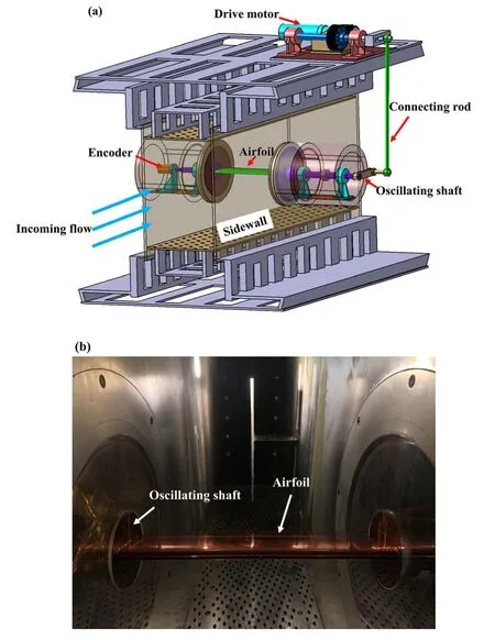
Figure 1.(a) NF-6 wind tunnel oscillating test system, (b)NACA0012 airfoil model in test section.
2.2.Test airfoil model
The NACA0012 airfoil model was used in this study, with a chord length of c=200 mm and a span length of l=400 mm, and the oscillating axis was located at the position of x/c=1/4 from the leading edge, as shown in figure 2(a).The dashed line in the figure indicates the internal cavity which was used for the installation of the sensor and the signal line layout, and after the sensor arrangement was completed, the model cavity was sealed by the cover plate.The model was made of aluminum materials (LC4)to reduce the rotational inertia under the premise of ensuring strength and stiffness.Therefore, the contact surface between the model and the wind tunnel needed to be insulated with Kapton tape.The gaps between the oscillating airfoil model and the insulating endplates were kept at less than 1 mm to minimize the flow leakage from the pressure side to the suction side and to maintain the two-dimensional characteristics of the flow field.To study the physical characteristics of the interaction between the DSV structures and the MP-DBD actuation, seven Kulite XCQ-093 pressure sensors were flush-mounted on the airfoil upper surface, the reference tube of which was sealed inside the airfoil cavity,as shown in figure 2(b); the mounted positions of the pressure sensors are given in table 1.Since the thickness of the airfoil close to the trail edge is smaller than the height of the pressure sensor, the last position of the sensor was mounted at x/c=65%, and the rest of the pressure taps were blocked by the plug.To ensure the pressure in the cavity was constant,the signal line hole was sealed with mastic.A VXI data acquisition system was used to collect synchronously transient pressure data on the airfoil surface and the instantaneous incidence signal was obtained by the encoder.The acquisition precision was 16 bits analog-to-digital, and the maximum sampling frequency was 300 kHz.To investigate the unsteady characteristics of the dynamic stall with the MP-DBD actuation, the sampling rate of the present study was set to fs=20 kHz to ensure a sufficiently high temporal accuracy.
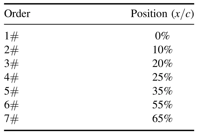
Table 1.Distribution of Kulite pressure sensors across the airfoil upper surface.
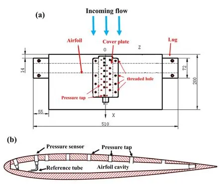
Figure 2.NACA0012 airfoil model.(a) Top view, (b) profile of airfoil cavity.
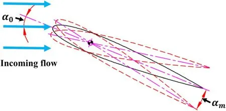
Figure 3.Features of airfoil pitching motion.
The pitching motion of the airfoil followed a sinusoidal pattern, and the instantaneous AOA can be written as a function of operating time t:
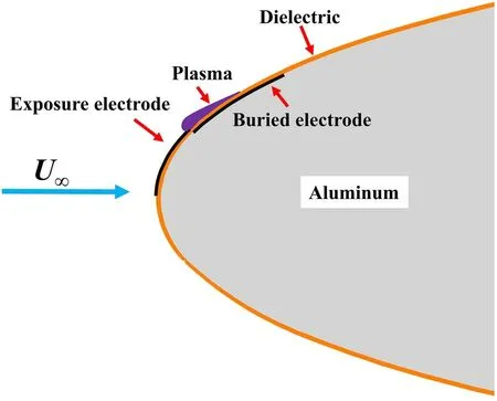
Figure 4.Arrangement of the plasma actuator.
whereα0is the mean AOA,αmis the pitch amplitude,andfis the oscillating frequency, respectively.In order to evaluate the unsteady level of the pitching motion, a parameter called reduced frequency was introduced, which can be written as the ratio of the time scale of the flow passing over the airfoil and the period of the pitching motion,k:
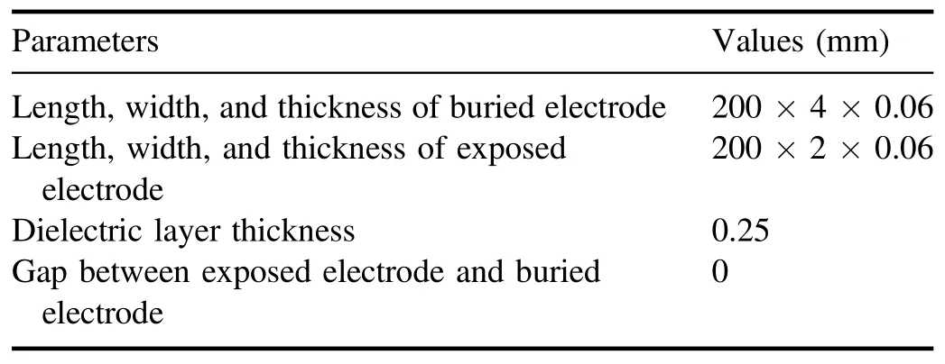
Table 2.Parameters for the MP-DBD plasma actuator.
where c andU∞are the chord length of the airfoil and freestream velocity, respectively.A schematic of the airfoil motion is shown in figure 3.
2.3.MP-DBD actuation system
Since the NF-6 wind tunnel is an all-steel structure, the shielding protection of DBD actuation with high voltage is particularly important for the MP-DBD flow control experiment.Except for the special insulating endplates, the conductors of the actuator in the wind tunnel test section are a high-voltage wire with a copper mesh shielding layer.To ensure the intensity and rigidity, an aluminum NACA0012 airfoil model was applied in this study, on which insulation modifications were conducted.A layer of Kapton tape was employed to cover the entire outer surface of the airfoil to isolate the buried electrode from the metal model.The plasma actuator arrangement was located at 3% chord length of the airfoil upper surface, and consisted of two copper tape electrodes separated by a dielectric layer composed of three layers of thick Kapton tape,as shown in figure 4.The configuration parameters for the MP-DBD plasma actuator used in the present experiment are given in table 2.It should be noted that the thickness of a single layer of Kapton tape is 0.07 mm,and the total thickness of the dielectric layer was slightly increased due to the additional adhesive layer we used in the fabrication process.
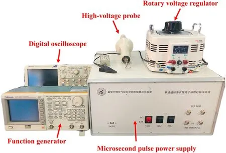
Figure 5.MP-DBD plasma actuator system.
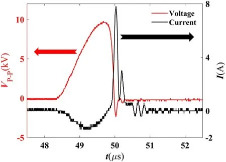
Figure 6.Voltage and current waveforms of the MP-DBD actuator(part of the cycle).
Figure 5 shows the MP-DBD plasma actuation system,including a self-developed microsecond-pulse power supply,a high-voltage probe (Type: Tektronix- P6015A), a function generator (Type: AFG3021), a digital oscilloscope (Type:TDSI1001B), and a rotary voltage regulator.In general, the function generator controls the waveform and the frequency of the output voltage of the plasma power supply, the voltage regulator is used to control the peak-to-peak value of output voltage, and the real-time voltage and current signals are fed back to the oscilloscope through the high-voltage probe.Figure 6 shows the voltage and current waveforms of an MPDBD actuation cycle, with a pulse width of 2 μs, pulse actuation frequency of 1 kHz,and peak-to-peak value of output voltage of Vp-p=12 kV,in which the rising edge of voltage is about 1.4 μs and the falling edge of voltage is about 0.6 μs.
The time-averaged electrical power consumption Pcof the MP-DBD can be obtained by integrating the voltage and current waveforms, which can be written as:
where v(t) and i(t) are the voltage amplitude and the instantaneous current, respectively, and T is the MP-DBD pulse period and equal to 0.001 s.Thus, the total power consumption of the MP-DBD in figure 6 is 9.38 W, and the power consumption per unit length is 0.47 W cm-1.
2.4.Data processing method
The pressure sensors employed in the present study were differential pressure type; the transient pressure data on the airfoil surfaceP(t) can be written as:
where t is the real time,Prefis the pressure of the reference tube,which can be seen as equal to the pressure in the cavity and collected by the pressure scanning valve,U(t) is the output signal from the sensor,U0is the electrical null of the sensor, andKis the sensor sensitivity factor, the units of which are mV psi-1.The unit of the final result of formula(4)needs to be transformed into Pascal for subsequent calculations.
The pressure coefficient is calculated as follows:
whereP∞is the static pressures in the freestream,γis the specific heat ratio of the flow, andρ∞andM∞are the density and Mach number of the freestream, respectively,acquired through the acquisition system of the NF-6 wind tunnel.
The transient pressure data with high temporal resolution contain extensive information on the nonlinear characteristics of the flow field.A wavelet packet analysis method was applied to decompose the original transient pressure data into pressure trend items and pulse pressure components with different frequency bands.According to the studies of Wei et al[37]and Visbal and Garmann[38],the occurrence of the boundary layer unsteady behavior of a pitching airfoil is accompanied by varying degrees of pressure fluctuations caused by the flow instability, including the phenomena of laminar separation,transition,vortex formation and shedding,and flow reattachment.A moving RMS method [39] was employed to detect these special aerodynamic phenomena,based on the sensitivity of the boundary layer to Kelvin-Helmholtz (K-H) instability.
3.Experimental results and analysis
In this section, the MP-DBD actuation authority on both the light and deep dynamic stall is discussed in detail.To explore the control trend of associated unsteadiness induced by the dynamic stall with the MP-DBD actuation,the dimensionless actuation frequencywherefpis pulse actuation frequency)is varied over a range of 0.5,1,2,and 3.Detailed statuses of the experiment and configuration parameters of the actuator are given in table 3.
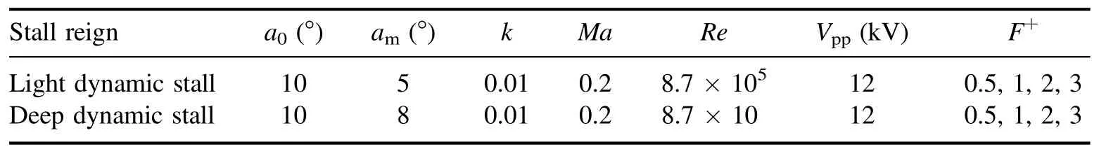
Table 3.Experimental parameters and MP-DBD configurations.

Figure 7.Pressure characteristics of a pitching cycle at x/c=10%.(a) AOA, (b) original and filtered pressure coefficient, (c) pulse pressure coefficient, (d) RMS of pulse pressure.
3.1.Light dynamic stall flow control
The light dynamic stall is characterized by the trailing edge separation gradually propagated upstream or a small-scale DSV, for which the stall regime is similar to static stall.Although the separation scale is smaller than that of deep stall,the deterioration of aerodynamic performance caused by the light dynamic stall is also a severe challenge to wind turbine airfoils.
The experimental Reynolds number in the present study was 8.7 × 10⁵; most of the current large wind turbines operate in this Reynolds number range.Figure 7 shows the original pressure coefficient Cp, filtered pressure coefficient Cpfwhich is acquired by the sixth layer coefficient of wavelet packet decomposition with a frequency bandwidth of 0-156.25 Hz, pulse pressure coefficient Cppdefined as Cpp=Cp- Cpf, and moving RMS of Cppover a pitching cycle at the position of x/c=10% for the case without MPDBD actuation.Clearly, the nonlinearity and unsteadiness of the boundary layer close to the leading edge are reflected by the pressure characteristics at this measurement point.Based on the stability degree of the boundary layer, the flow field evolution process can be divided into five stages: (1)laminar flow; (2) transition - under the influence of the cross-flow instability and the adverse pressure gradient, the intensity of the K-H rolls amplifies to the maximum,which is verified by the peak value of the RMS, and after the shedding of the detached shear layer,the transition phenomenon is completed with the fallback of RMS;(3)turbulence;(4)relaminarization- during this stage, the shedding of the coherent vortex structures also causes a drastic enhancement of RMS, and then the RMS gradually decreases and the flow reverts to laminar flow;(5)laminar flow.It is worth mentioning that,at this pressure measuring point, the RMS value of the laminar flow is higher than that of turbulence, because this pressure measuring point is just below the region of the laminar flow separation bubble(LSB),and the pressure fluctuations caused by the detached shear layers of the LSB lead to a higher instability than turbulent structures.
Figure 8 shows the phase-averaged pressure coefficient variation of each pressure measurement point with and without MP-DBD actuation.The baseline represents the operation without MP-DBD actuation, and the other curves correspond to operations of the MP-DBD actuation with different F+.Note that the symbols ‘↑’ and ‘↓’ indicate the upstroke and the downstroke motion respectively.Obvious pressure bumps are observed in figures 8(e)-(g), which are induced by the reverse flow from the trailing edge separation.The peak value of the pressure bump corresponds to the largest scale trailing edge separation.Apparently, under the effects of MP-DBD actuation, the trailing edge separation is suppressed, and as the dimensionless actuation frequency F+increases,the suppression effect becomes more obvious.With the initiation of the downstroke, the pressure bumps are recovered by the gradually reduced adverse pressure gradient and trailing edge separation.The inflection point of the pressure coefficient indicates the flow reattachment, marked as a red dashed arrow in figure 8(e); compared to the uncontrolled baseline, MP-DBD actuation plays a role in promoting the flow reattachment,and with increasing F+,the onset of the flow reattachment is advanced by the higherfrequency pressure wave disturbance.The MP-DBD actuation also improves the flow characteristics close to the leading edge, as shown in figure 8(b); the suction peak is enhanced and the pressure jumps caused by the transition and relaminarization are also alleviated, and hence, under higher actuation frequencies, better control effects are achieved.
As the actuation frequency increases, the ability of MPDBD actuation to inject high-momentum flow into the boundary layer is also gradually improved, which helps to promote the stability of the boundary layer and the ability to resist the adverse pressure gradient.
From figure 8(b), it can be found that the flow field around the measurement point of x/c=10% is very complex, including the phenomena of laminar fluctuation, transition,turbulence,and relaminarization.The RMS value of the pulse pressure of this measuring point is shown in figure 9;compared to the uncontrolled baseline, the pressure fluctuation caused by the K-H instability during the transition process is significantly reduced by the MP-DBD actuation,verified by the reduced RMS peak value,and with increasing F+, the K-H instability between the LSB and the detached shear layer is suppressed more obviously.Another promotion of the MP-DBD actuation is the delay of the transition onset and the acceleration of relaminarization.Using the AOA at the RMS peak value as the criterion AOA of the transition and the relaminarization onset, for the uncontrolled case, the onset instantaneous AOA values of transition and the relaminarization are 6.4°↑ and 6.2°↓, respectively; however,under the controlled case of F+=3, the onset instantaneous AOA values of transition and the relaminarization are 7.1°↑and 7.1°↓,respectively.The mitigation of pressure fluctuation by MP-DBD actuation contributes to reducing the unsteadiness of airfoil aerodynamics and avoids additional aeroelastic loads, and the promotion of transition delay and the earlier relaminarization has positive impacts on the hysteresis effect of dynamic stall.
Figure 10 shows the time-frequency diagram of wavelet packet analysis of the pulse pressure at the position of x/c=10%.For the uncontrolled case, a laminar fluctuation with a frequency band of 1.5-4.5 kHz is observed in the initial stage of upstroke, and after the flow relaminarization,another laminar fluctuation is also observed in the end stage of downstroke with a frequency band of 2-3 kHz.This strong laminar flow fluctuation explains the reason why the RMS values before the transition and after the relaminarization are higher than those of the turbulence in figure 7.During the stage of transition, the frequency of K-H instability increases rapidly from 0.3 to 5 kHz with the airfoil upstroke motion,and after the completion of the transition, the concentrated time-frequency characteristics are replaced by small-scale coherent vortex structures.In addition, with the downstroke motion of the airfoil, the process of relaminarization is accompanied by a gradual weakening of K-H instability.

Figure 8.Histories of phase-averaged pressure coefficient with and without MP-DBD actuation during a pitching cycle.(a)x/c=0%,(b)x/c=10%, (c) x/c=20%, (d) x/c=25%, (e) x/c=35%, (f) x/c=55%, (g) x/c=65%, (h) AOA.
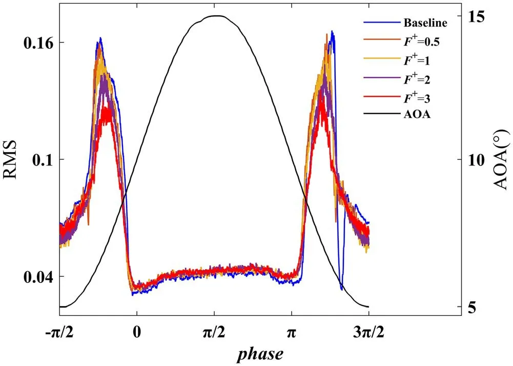
Figure 9.Variation of RMS with AOA at x/c=10% with and without MP-DBD actuation.

Figure 10.Time-frequency spectra of phase-averaged pulse pressure at x/c=10%.(a) AOA, (b) baseline, (c) F+=0.5, (d) F+=1,(e) F+=2, (f) F+=3.
For the controlled cases of F+=0.5 and F+=1, the intensities of laminar fluctuation and the K-H rolls are significantly weakened by the pressure waves induced by MPDBD actuation, and the frequency bands are also noticeably widened.However, for the controlled cases of F+=2 and F+=3, the laminar fluctuation is replaced by relatively low frequency band disturbances, corresponding to the higherorder harmonic responses of the MP-DBD actuation frequency;even the structures of K-H rolls are broken down into pressure disturbances with multiple frequency bands, also corresponding to the harmonic responses of the actuation frequency.It can be concluded that the shear layer instabilities in the region of laminar fluctuation are sensitive to perturbations induced by MP-DBD actuation,and the interaction of the shear layer with high-frequency pressure waves leads to the formation of coherent structures which can entrain highmomentum flow into the unstable region, suppressing the growth of laminar fluctuation and K-H rolls.
3.2.Deep dynamic stall control
Compared with light dynamic stall, deep dynamic stall is a phenomenon of unsteady separation of the boundary layer which is characterized by a well-defined DSV structure, and leads to an extra viscous aerodynamics force, resulting in large oscillatory loads that can significantly reduce the performance of the airfoil.Figure 11 shows the Cp, Cpp, and RMS of Cppover a pitching cycle at the position of x/c=10%,without the MP-DBD actuation.Similar to the light stall case, the evolution process of deep dynamic stall is divided into five parts.An obvious distinction from the light stall is observed in stage 3,where a sharply dropping negative pressure peak occurs at 17.5°↑, validating the formation of DSV,and the peak value of RMS reaches the maximum at the same time, as shown in figure 11(d).
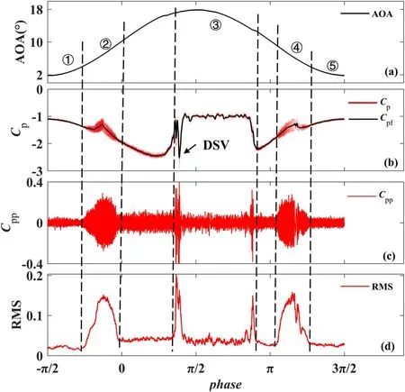
Figure 11.Pressure characteristics of a pitching cycle at x/c=10%.(a) AOA, (b) original and filtered pressure coefficients, (c) pulse pressure coefficient, (d) RMS of pulse pressure coefficient.
Figure 12 shows the variation of the phase-averaged pressure coefficient with and without MP-DBD actuation at the position of x/c=10%; the solid blue circle indicates the formation of DSV.Using the pressure coefficient when DSV is formed to express the suction strength of DSV,thus,for the uncontrolled case, the onset AOA of DSV is 16.9°↑and the suction peak of the DSV is -2.013, and for the controlled cases of F+=0.5, F+=1, F+=2, and F+=3, the onset AOA values of DSV are 17.3°↑, 17.4°↑, 17.5°↑, and 17.5°↑,respectively, and the suction peaks of the DSV are -1.73,-1.65, -1.57, and -1.58, respectively.The trend of the actuation effects on the formation of DSV is improved with the increased actuation frequency;however,this trend appears to have a definite limit,as when F+increases from 2 to 3,the onset AOA and the strength of the DSV are almost identical.Before the formation of DSV, the pressure coefficient oscillates sharply with increasing AOA under the MP-DBD actuation, and multiple negative suction peaks are observed,indicating that the accumulation effect of vorticity is replaced by a stream of small coherent vortices, resulting in a weaker DSV, particularly for the case of high actuation frequency.
Figure 13 shows the results of RMS of Cppat the position of x/c=10%with and without the MP-DBD actuation in the deep dynamic stall regime; as with the flow control authority of light dynamic stall, the MP-DBD actuation plays a role in suppressing the fluctuation of K-H rolls.Moreover, during the stage of unsteady separation, the peaks of RMS, marked as solid squares, are alleviated by the MP-DBD actuation which also shows that the strength of DSV is reduced by increasing actuation frequency.For controlled cases, small peaks are observed before the RMS reached its maximum corresponding to the small-scale vortex structures formed by the interaction between pressure wave perturbation and the detached shear layers.However, the MP-DBD actuation seems to have no clear control trend for flow reattachment.
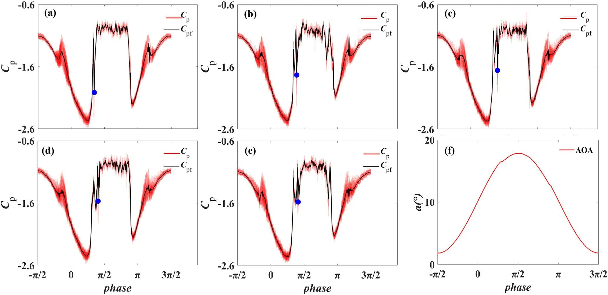
Figure 12.Phase-averaged pressure coefficient of different F+.(a) Baseline, (b) F+=0.5, (c) F+=1, (d) F+=2, (e) F+=3, (f) AOA.

Figure 13.Variation of RMS with AOA at x/c=10% with and without MP-DBD actuation.
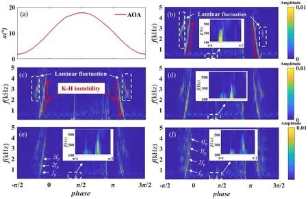
Figure 14.Time-frequency spectra of phase-averaged pulse pressure at x/c=10%.(a) AOA, (b) baseline, (c) F+=0.5, (d) F+=1, (e)F+=2, (f) F+=3.
Figure 14 shows the time-frequency spectra diagram of the phase-averaged pulse pressure at the position of x/c=10% in the deep dynamic stall regime.The flow maintains laminar during the AOA ranges of initial upstroke and end downstroke.As with the control effects of light dynamic stall, the laminar fluctuation and K-H instability of the transition are suppressed by the MP-DBD actuation, and the frequencies of shedding shear layers and the K-H rolls are driven by the actuation frequency for the cases of F+=2 and F+=3.A distinct region of elevated spectral amplitude is observed in the AOA range of 16.8°↑to 17.1°↑with a frequency band of 100-400 Hz, corresponding primarily to the vorticity accumulation and the inception of the DSV, as shown in figure 14(b).However, for the controlled cases of F+=1, F+=2, and F+=3, a relatively small-scale unsteadiness is observed before the formation of the DSV,with a frequency band of 100-200 Hz, corresponding to the induced coherent vortices.In addition, the spectral amplitude of the DSV is reduced because the accumulating vorticity near the leading edge is removed by the induced perturbations,and when F+is increased to 3,the dominant frequency of DSV is enhanced to about 300 Hz, which appears to indicate that the actuation frequency is close to the natural frequency of the DSV recirculation region,whose instabilities and viscous dissipation in the recirculation tend to increase.Thus, as a result of the resonance effect, the performance of the MP-DBD actuator no longer improves with increasing actuation frequency.
4.Conclusions
The dynamic stall phenomenon is a key factor in the deterioration of wind turbine performance, which may lead to aerodynamic losses,oscillatory loads,and structural response such as aerodynamic flutter;thus,the problem of suppression of dynamic stall has become an important issue in the field of flow control.In the present study, a single MP-DBD plasma actuator was mounted at 3%over the length of the airfoil from the leading edge to investigate the actuation control effects on both light and deep dynamic stall by wind tunnel experiments.Based on the experimental results, the main conclusions are as follows:
(1) For the light dynamic stall,the MP-DBD plasma actuator plays the role of suppressing flow separation from the trial edge.The induced pressure wave perturbation also results in earlier flow reattachment due to the highmomentum freestream flow being entrained into the boundary layer, and actuation effects are promoted with the increasing dimensionless actuation frequency F+.
(2) The laminar fluctuation and K-H instabilities of transition and relaminarization are observed in both the light and deep dynamic stall regimes and alleviated by the MPDBD actuation, which is verified by the reduced RMS value and spectral amplitude with increasing F+.For the controlled cases of F+=2, and F+=3, the laminar fluctuation is replaced by relatively low frequency band disturbances corresponding to the higher-order harmonic responses of the MP-DBD actuation frequency.The alleviated K-H rolls lead to the delay of the transition onset and earlier flow reattachment, which improves the hysteresis effect of the dynamic stall.
(3) The control effects of MP-DBD actuation on the deep dynamic stall include suppressing the strength and delaying the formation of the DSV.With increasing AOA, the accumulation effect of vorticity is replaced by a stream of small coherent vortices induced by the pressure wave perturbation, resulting in a weaker DSV,especially at high actuation frequency.Although the control effect still improves with increasing F+, the strength and onset AOA of DSV for the controlled cases of F+=2, and F+=3 are almost the same, which appears to indicate that, when the actuation frequency is close to the natural frequency of the DSV recirculation region, the instabilities and viscous dissipation tend to increase, as a result, the resonance effect limits further improvement of the MP-DBD performance.
Acknowledgments
This work is supported by National Natural Science Foundation of China (Nos.12172299 and 1190021162).
猜你喜欢
艺术品鉴(2021年30期)2021-11-26
中华魂(2021年10期)2021-10-15
Chinese Physics B(2021年7期)2021-07-30
Plasma Science and Technology(2021年2期)2021-02-27
上海故事(2019年5期)2019-05-21
新青年(2018年3期)2018-03-16
小天使·二年级语数英综合(2017年12期)2017-12-05
喜剧世界(2016年9期)2016-11-26
汽车零部件(2015年4期)2015-12-22
 Plasma Science and Technology2023年3期
- Plasma Science and Technology的其它文章
- Relativistic toroidal light solitons in plasma
- Valley-dependent topological edge states in plasma photonic crystals
- Bulk moduli of two-dimensional Yukawa solids and liquids obtained from periodic compressions
- Modeling of magnetized collisional plasma sheath with nonextensive electron distribution and ionization source
- Observation of the poloidally asymmetrical density perturbation of sawtooth collapse on J-TEXT
- Alfvén continuum in the presence of a magnetic island in a cylinder configuration