
Impact of resonant magnetic perturbation on blob motion and structure using a gas puff imaging diagnostic on the HL-2A tokamak
2023-10-08 08:20JinbangYUAN袁金榜MinXU许敏YiYU余羿BodaYUAN袁博达LinNIE聂林XiaoquanJI季小全TengfeiSUN孙腾飞AoWANG王傲andJiquanLI李继全
Plasma Science and Technology 2023年9期
Jinbang YUAN(袁金榜),Min XU(许敏),∗,Yi YU(余羿),Boda YUAN(袁博达),Lin NIE(聂林),Xiaoquan JI(季小全),Tengfei SUN(孙腾飞),Ao WANG(王傲)and Jiquan LI(李继全)
1 Southwestern Institute of Physics,Chengdu 610041,People’s Republic of China
2 Sino-French Institute of Nuclear Engineering and Technology,Sun Yat-sen University,Zhuhai 519082,People’s Republic of China
Abstract The impact of resonant magnetic perturbation(RMP)on blob motion and structure in the SOL of the HL-2A tokamak is studied using a gas puff imaging diagnostic.Ellipse fitting is applied to study the structure and motion of blobs quantitatively.The radial locations,amplitudes and scale sizes of blobs are obtained based on the fitted ellipse.Furthermore,based on the measurement of blob location,the radial and poloidal velocities of blobs are calculated.With the application of RMP,the edge poloidal shear flow is significantly weakened and the wave number spectrum changes from quasisymmetric to significantly up-down asymmetric.The application of RMP also causes the detected blob location to be much further into the far scrape-off layer(SOL)and increases the blob amplitude.Blob poloidal velocity in the SOL is slowed.Larger-size and longer-lifetime blobs are observed with RMP.With the application of RMP,stronger-amplitude and larger-size blobs are detected in the far SOL and they may cause a more serious erosion problem to the first wall.
Keywords: resonance magnetic perturbations,blob structure,blob motion,gas puff imaging
1.Introduction
Resonant magnetic perturbation(RMP) coils have been widely used to suppress edge localized modes(ELMs)worldwide since the discovery on DIII-D that the application of RMP can lead to full ELM suppression[1,2].ITER design work proposed the application of RMP to stabilize ELM and feedback stabilization of resistive wall modes and to increase vertical stability [3].In addition,RMP is used to control the vertical plasma position and to control the interaction between plasma and the first wall [4,5].
The application of RMP is also used to modify edge turbulence and transport.The impact of RMP on edge turbulence is observed to be dependent on RMP generation modes and plasma parameters.On TEXT,experiments found that particle transport increased by typically 30% with magnetic islands created by externally applied resonant magnetic fields [6].Experiments on TEXTOR showed that with RMP the local turbulent flux reversed sign from radially outwards to inwards [7,8].On MAST,the edge turbulence density fluctuation level decreased and the density probability distribution function showed an asymmetrization towards non-Gaussian shapes with RMP [9].In DIII-D H mode plasma,long-wavelength turbulence and transport increased dramatically and global energy confinement decreased with the application of RMP [10].Later work showed an increase in density fluctuations at microturbulent scales with increasing RMP amplitude [11].KSTAR tokamak experiments alsoobserved that application of RMP increased the density fluctuation level [12].Recent experimental studies on DIII-D provided a mechanism for the effect of RMP on turbulence density fluctuations.RMP reduces the flow shear rate and thereby disrupts the turbulence shear suppression mechanism[13].In addition,research on the interaction between magnetic island induced by RMP and turbulence has been widely reported on EAST [14-16],J-TEXT [17-19] and HL-2A[20,21].Furthermore,the impact of RMP on blobs has attracted significant attention.Blobs are isolated high-density structures that are usually formed in the plasma edge or near the separatrix,and move fast and radially towards the first wall [22-25].Separate studies have shown that blobs in the boundary plasma can account for up to 50% of the total transport associated with edge turbulence [26-28],and blobs can significantly increase interactions between the plasma and the first wall by causing non-diffusive plasma transport[29-31].Simulation results predicted that larger-scale blobs can maintain a stable structure for longer [29].However,the blob birth process still remains an open issue [32].
The impact of RMP on edge poloidal shear flow(also radial electric field)has also been studied on many tokamaks.On TEXTOR,the application of the DED(Dynamic Ergodic Divertor) increases the rotation in the scrape-off layer(SOL)and slows the rotation at the edge [33],and similar experimental phenomena are also observed on MAST [9].
It is generally believed that poloidal shear flow plays an essential role in controlling turbulence transport for its shearing effects on turbulent eddies,as predicted by theories[34-36].Edge poloidal flow speed varies in the radial direction,perpendicular to the flow direction,and usually has the maximum shearing rate near the separatrix.It is widely accepted that the poloidal shear flow tilts the eddies,decreases their radial extent and elongates them poloidally.In some simulations,the shear flow also breaks up large eddy structures [36].
Experimental observations on TEXTOR provided evidence of eddy breaking and tilting caused by edge shear flow.Results showed that the magnitude of the flow shearing rate plays a key role in eddy tilting or breaking [37].Further experiments showed that as the poloidal flow is slowly enhanced,thekr-kθspectrum changes from roughly symmetric to elliptic to finally wider and less stretched,where the widening of the spectrum implies the breakup of eddies [38].
In this paper,the impact of RMP on blob motion and structure on the HL-2A tokamak is studied using a gas puff imaging(GPI) diagnostic.The rest of the paper is organized as follows.Section 2 gives the introduction of the experimental setup.Section 3 presents blob diagnostics and data analysis.High spatial and temporal resolution of plasma turbulence diagnostics-GPI is used to measure the 2D turbulence density fluctuations.Ellipse fitting is applied to study the structure and motion of blobs quantitatively.Section 4 analyzes the impact of RMP on blob motion and size.Finally,in section 6,discussion takes place and the paper is concluded.
2.Experimental setup
HL-2A is a medium-size tokamak,which is performed in deuterium plasmas and typically operated under limiter or lower single-null divertor configurations [39-41].Its major radius isR=1.65 m and its minor radius isr=0.4 m.
The experiment is carried out in Ohmic discharge at lower single-null divertor configuration(shots#37777 and#37778).The time evolution of the main discharge parameters in this experiment is shown in figure 1.The experiment was carried out under Ohmic heating with a plasma current(IP)of 160 kA,a toroidal magnetic field(Bt) of 1.6 T,line-averaged density(ne) of 1.3×10¹⁹m-3and horizontal displacement of the magnetic axis(hd)around 0.These parameters remained almost constant without/with the application of RMP.Shot#37777 is the reference shot without RMP and shown by blue color,and shot#37778 is applied with 10 kA RMP(m/n=3/1)during the period oft=1300-1400 ms and shown by red color.The magnetic field perturbation componentm/n=3/1 by RMP is more than 7 Gs on theq95surface andm/n=3/1 magnetic islands are created on theq=3 surface.More details about the RMP coils on HL-2A can be found in [42].These parameters are the common discharge parameters of the HL-2A tokamak and are highly repeatable.The helium gas puff by GPI is initiated at 1250 ms to observe the modification of RMP on poloidal shear flow and blob properties duringt=1300-1400 ms.The results in this paper are calculated from 1300 to 1400 ms of GPI measurements.
Measurement of the poloidal velocity profile is done by GPI in the middle plane using the time delay estimation method [43].The profiles of poloidal velocity(Vθ) and shearing rate(ωs) ofVθare shown in figure 2,wherer-rseprepresents the distance from the separatrix,andωsis calculated asωs=d(Vθ)/dr.The error bars are shown by corresponding shadow colors.The poloidal velocity is significantly modified with the application of RMP.The poloidal velocity profilebecomes shallower and the maximum shearing rate becomes much weaker from-1.88×10⁵to-0.908×10⁵s-1with the application of 10kA RMP.Similar experimental phenomena were also reported on TEXTOR[33]and MAST[9].Based on these papers,it is proposed that RMP leads to an increased electron loss rate,which charges the plasma edge more positively.This mechanism explains the shallower poloidal velocity profile observed.
With the application of 10 kA RMP,the poloidal shear flow becomes much weaker.The impact of RMP on blob properties is presented in the following sections.
3.Blob diagnostics and data analysis
3.1.GPI diagnostics
The motion and structure of blobs are observed using GPI diagnostic,which is the same as reported previously[44,45].The set of GPI diagnostics used in this experiment is a viewing area 15 cm×15 cm region in the radial-poloidal plane perpendicular to the localBfield and a fast camera that records at 100 000 frames/s using a 128×128 pixel array.The time interval between two consecutive frames is 10μs,and the spatial resolution of the optical system is around 0.2 cm at the GPI gas cloud.A long nozzle is used to puff the helium gas into the plasma boundary region.
3.2.Blob data analysis
In this paper,the blob tracking analysis based on GPI data is done as follows.The GPI data are first normalized to a 1 ms rolling time-average of neighboring images(100 frames) in order to identify the maxima in each normalized image.A blob is defined as the region where the local normalized,smoothed fluctuation intensity exceeds 1.5.A contour line is generated in the region of intensity equal to 1.5 and then an ellipse is fitted to this contour.
In order to study the structure and motion of blobs quantitatively,ellipse fitting is applied to the 1.5 contour of blobs.An illustration of blob ellipse fitting used in this study is shown in figure 3.Figure 3(a) shows the normalized intensity of a blob in one frame in a 3D coordinate system,wherex,y-direction coordinates represent the radial and poloidal pixel,respectively,and thez-direction coordinate represents the normalized intensity of the GPI data.Figure 3(b) is the projection of(a) on the radial-poloidal plane.The separatrix is shown by the black dashed line,and then an ellipse(in red)is fitted to the contour level of 1.5,and the blob scale lengths(LrandLθ)are defined from the ellipse fitting,as shown in figure 3(c).Based on the ellipse fitting of blobs,the key parameters of each detected blob are obtained:the blob radial location(marked as the center of the ellipse with respect to the separatrix at the radial row),the blob amplitude(defined as the maximum normalized intensity of GPI signal),the radial and poloidal scale length of the blob(LrandLθ,as in figure 3(c)) and the blob area(calculated as the ellipse area).The procedure for calculatingLrandLθof the blob is as follows.First,a rectangular coordinate system is established with the center of the ellipse as the origin,as shown in figure 3(c),and thex-andy-axes are the radial and poloidal directions,respectively.Thex-axis has two intersections with the ellipse,and the distance between these two intersections is defined asLrof the blob.Similarly,the distance between two intersections of they-axis with the ellipse is defined asLθof the blob.

Figure 3.Illustration of a blob ellipse fitting:(a) normalized intensity of a blob in the 3D coordinate system,(b) the 2D projection on the radial-poloidal plane of(a).Separatrix is shown by the black dashed line,(c)an ellipse(in red)is fitted to the contour level of 1.5(shown by the black dotted line) and blob scale lengths(Lr and Lθ) are defined from the ellipse fitting in(c).

Figure 4.(a) Typical normalized GPI image without RMP and(b)corresponding 2D wave number spectrum of(a).(c) Typical normalized GPI image with RMP and(d) corresponding 2D wave number spectrum of(c).

Figure 5.Contour plots of average 2D wave number(kr- kθ)spectra in instances(a) without RMP and(b) with 10 kA RMP situations.
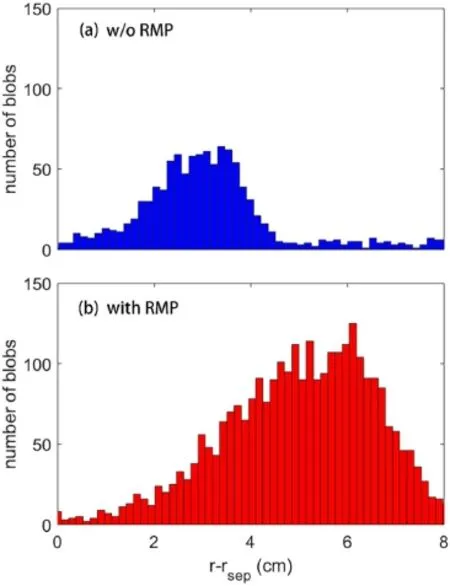
Figure 6.Detected location of blobs in the SOL in instances(a)without RMP and(b) with RMP.
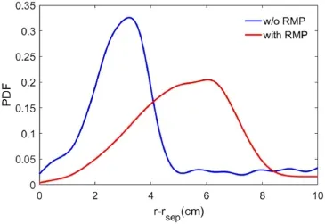
Figure 7.PDF of the detected location of blobs in the SOL without(in blue) and with(in red) RMP.
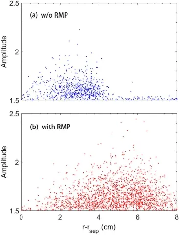
Figure 8.Radial distributions of individual detected blob amplitude in instances(a) without RMP and(b) with RMP.

Figure 9.Profiles of average amplitude of blobs in instances(a)without RMP(in blue) and(b) with RMP(in red).
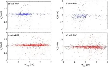
Figure 10.Velocity of individual blobs in instances of(a)radial velocity without RMP,(b)poloidal velocity without RMP,(c)radial velocity with RMP,(d) poloidal velocity with RMP.
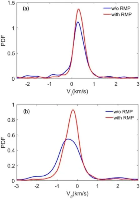
Figure 11.PDF of blob(a) radial velocity and(b) poloidal velocity without(in blue) and with(in red) RMP.
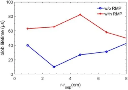
Figure 13.Profiles of the average blob lifetime without(in blue)and with(in red) RMP.
Furthermore,based on the measurement of blob location,the radial and poloidal velocities of blobs are calculated as the radial and poloidal displacements divided by the interval time.
Typical normalized GPI images without and with RMP are shown in figures 4(a)and(c),respectively.The blob shape in figure 4(a)is close to circular,while in figure 4(c)the blob shape is stretched with a tilted angle.To characterize the turbulence eddy shapes,a 2D space fast Fourier transform(2D-FFT)is performed.Thekrandkθare calculated from the space 2D-FFT of GPI images,and the 2D wave number spectra of figures 4(a) and(c) are shown in figures 4(b) and(d),respectively.The wave number spectrum changes from quasisymmetric to significantly up-down asymmetric with the application of 10 kA RMP,reflecting the modification of blob shape in the corresponding GPI images.
Contour plots of 2D wave number(kr-kθ) spectra of GPI images are plotted in figure 5.Each spectrum is averaged over 1000 images.With the application of RMP,the wave number spectrum changes from quasisymmetric in figure 5(a)to significantly up-down asymmetric in figure 5(b).The asymmetric wave number spectrum indicates that turbulence structures are stretched with a tilted angle.Similar phenomena were reported on TEXTOR,which used electrode biasing to modify poloidal shear flow [38].More experimental results with respect to the shearing effect on blob size are presented in section 4.3.
4.Impact of RMP on blob motion and size
4.1.Impact of RMP on location and amplitude of blobs
Due to the large measurement area covered by GPI diagnostics,the radial locations of blobs are marked as the center of the fitted ellipse with respect to the separatrix in the radial direction regardless of poloidal position.The number of blobs detected per radial zone is clearly different between without and with RMP cases,as shown in figure 6.
Without RMP,the largest number of blobs per zone is found around 2-4 cm outside the separatrix and there are few blobs beyond 4 cm.However,with RMP there are very fewblobs near the separatrix,and most of the blobs are detected around 4-7 cm.The number of detected blobs without RMP at 2 cm<r-rsep<4 cm is around 50 per zone,while the number of detected blobs with RMP at 5-7 cm is around 100 per zone.The number of detected blobs increases significantly with the application of RMP.
Further analysis of the most probable location of the detected blobs is done using statistical methods.The probability density functions(PDFs)of the detected location of the blobs in the SOL without and with RMP are shown in figure 7.The results show that the most probable location of blobs detected moves from 3.2 ± 0.3 to 6.0 ± 0.3 cm in the SOL.In other words,when RMP is applied,there are many more blobs detected in the far SOL.
The radial distributions of individual detected blob amplitude without RMP and with RMP are shown in figure 8.The detected locations of strong amplitude blobs(amplitude>2)are limited to the range of 2 cm<r-rsep<3 cm without the application of RMP.In other words,no strong amplitude of blobs can propagate into the far SOL.However,whenIRMP=10 kA RMP is applied,the detected locations of strong amplitude blobs(amplitude>2) are distributed in a larger range of 3.2 cm<r-rsep<6.8 cm.The possible physical process can be that as the RMP is applied,the weaker shear flow leads to strong amplitude blobs propagating much further into the far SOL.These blobs may deposit on the first wall and cause a serious erosion problem.
The profiles of average amplitude of blobs without RMP and with RMP are shown in figure 9.The average amplitude of blobs is enhanced from 1.55 to 1.65 when RMP is applied.
The impact of RMP on blob location and amplitude is quite clear.The application of RMP causes the detected blob location to be much further into the far SOL and increases the blob amplitude.To summarize,there are more and higher amplitude blobs in the far SOL with RMP.
4.2.Impact of RMP on blob velocity
Based on the measured locations of blobs,the radial and poloidal velocities can be calculated as the blob radial and poloidal displacements divided by the interval time between continuous frames.Note that the blob velocity is calculated only when the following two conditions are met: the blob lasts at least two successive frames(20μs) and the furthest displacement of blobs in one dimension in two successive frames is 5 cm,otherwise they are considered to be two independent blobs.In other words,the maximum blob velocity allowed in one dimension is 5 km s-1in this study.
The radial and poloidal velocities of individual blobs without and with RMP are shown in figure 10.The blob radialvelocities without and with RMP are mostly positive,as shown in figures 10(a) and(c),which means that most blobs are moving radially outwards(to the wall).Most of the blob poloidal velocities are negative,as shown in figures 10(b)and(d),which means that most blobs are moving downwards,which is along the ion-diamagnetic drift velocity direction.The poloidal velocities of most blobs in the SOL are along the direction of poloidal shear flow in the SOL.This may indicate that the poloidal shear flow has significant influence on the poloidal motion of blobs.
The distributions of radial velocities of blobs with and without RMP are similar and most blob radial velocities are distributed in theVr>0 region.However,the PDF of blob poloidal velocity is clearly different between the without RMP and with RMP cases,as shown in figure 11(b).The distribution of blob poloidal velocity with RMP is shifted to the more positive direction compared with the distribution without RMP,which means that the poloidal velocity of blobs decreases with RMP,which is consistent with the modification of edge shear flow by RMP.It is natural that the most probable poloidal velocity also decreases with RMP.The most probable poloidal velocity of blobs without RMP is-0.46 km s-1and the most probable poloidal velocity of blobs with RMP is-0.22 km s-1.
In general,RMP has little effect on the blob radial velocity but a noticeable effect on the poloidal velocity.An application of RMP slows blob poloidal velocity in the SOL.
4.3.Impact of RMP on blob size
It is generally believed that poloidal flow plays a key role in the turbulent eddy shape and formation.Previous experimental observations on the TEXTOR tokamak prove that whether shear flow tilts or splits the turbulent eddies depends on the magnitude of the flow shearing rate.Increasing the shearing rate changes the mode of effect from tilting to splitting and,consequently,reduces the turbulent transport [38].
Experiments in this study prove that the RMP weakens the poloidal shear flow discussed in section 2.Furthermore,the impact of weakened shear flow on turbulence blob sizes is studied in this section.
The profiles of the average blob size:(a)radial length,(b)poloidal length,(c) blob area without(in blue) and with(in red) RMP are shown in figure 12.Blob radial and poloidal sizes increase significantly with the application of RMP,especially near the separatrix.The blob area is also much larger than that without RMP.This observation verifies the assumption that the impact of shear flow on blobs changes from tearing and splitting to tilting only as the poloidal shear flow becomes weakened with RMP,resulting in larger-size blobs being detected.Furthermore,the impact of RMP on blob lifetime is also calculated.
The profiles of the average blob trail lifetime without(in blue)and with(in red)RMP are plotted in figure 13.It is clear that under the impact of RMP,the average lifetime of blobs ismuch longer.Combined with larger blob size,it can be inferred that the larger the blob size is,the longer the lifetime is,which is consistent with the simulation results [29].This also indicates that as the shearing rate of edge poloidal shear flow becomes weaker with the application of RMP,largersize and longer-lifetime blobs exist in the far SOL.
5.Conclusion
In this study,the impact of RMP on blob motion and structure on the HL-2A tokamak is determined using a GPI diagnostic.The edge turbulence fluctuation data by GPI with high spatial(2 mm×2 mm) and temporal(10μs) resolutions guarantee the quantitative measurements of the blob structure and motion in the radial-poloidal plane.A blob is identified when the condition that the normalized amplitude exceeds 1.5 is met and then an ellipse is fitted to the contour of the blob.The radial locations,amplitudes and the scale sizes of blobs are obtained based on the fitted ellipse.Furthermore,with the measurement of blob location,the radial and poloidal velocities of blobs are calculated.
With the application of RMP,the edge poloidal shear flow is significantly weakened and thekr-kθspectrum shifts from wider and less stretched to clearly tilted.This may imply that as the shear flow becomes weaker,the shearing effect changes from tearing and splitting to tilting only.This can be verified by the increase in blob size with RMP.
The application of RMP also causes the detected blob location to be much further into the far SOL and increases the blob amplitude and lifetime.The blob poloidal velocity in the SOL is slowed and larger-size and longer-lifetime blobs are observed with RMP.With RMP,stronger amplitude and larger blob size is detected further into the SOL,and these blobs may cause a more serious erosion problem to the firstwall.Thus,enhanced blob transport with the application of RMP needs to be considered for the ITER design work and future operations.
Acknowledgments
The authors thank the HL-2A team at SWIP for their assistance with the experiments.This work is supported by the National Key Research and Development Program of China(Nos.2022YFE03100002,2022YFE03010004 and 2019YFE03060002),National Natural Science Foundation of China(Nos.U1867222,U1967206 and 51821005) and the Sichuan Natural Science Foundation(Nos.2022NSFSC1791 and 2020JDTD0030).
ORCID iDs
猜你喜欢
悦游 Condé Nast Traveler(2022年11期)2022-05-30
江苏教育·书法教育(2021年3期)2021-01-17
美与时代·美术学刊(2020年3期)2020-06-29
数学学习与研究(2018年16期)2018-11-12
快乐语文(2018年25期)2018-10-24
家庭影院技术(2017年9期)2017-09-26
黄金时代(2017年3期)2017-06-30
人大建设(2017年11期)2017-04-20
机电信息(2015年28期)2015-02-27
 Plasma Science and Technology2023年9期
- Plasma Science and Technology的其它文章
- Plasma-activated hydrogel: fabrication,functionalization,and effective biological model
- Propagation of surface magnetoplasmon polaritons in a symmetric waveguide with two-dimensional electron gas
- Investigation of electron cyclotron wave absorption and current drive in CFETR hybrid scenario plasmas
- Inversion techniques to obtain local rotation velocity and ion temperature profiles for the x-ray crystal spectrometer on EAST
- Comparison of methods for turbulence Doppler frequency shift calculation in Doppler reflectometer
- Invariant manifold growth formula in cylindrical coordinates and its application for magnetically confined fusion