
Synergistic effect of electrode defect regulation and Bi catalyst deposition on the performance of iron–chromium redox flow battery
2023-11-18 09:53QuanXuSiyangWangChunmingXuXinyiChenSenweiZengChuanyuanLiYangZhouTianhangZhouYingchunNiu
Chinese Chemical Letters 2023年10期
Quan Xu, Siyang Wang, Chunming Xu, Xinyi Chen, Senwei Zeng, Chuanyuan Li,Yang Zhou, Tianhang Zhou, Yingchun Niu
State Key Laboratory of Heavy Oil Processing, China University of Petroleum-Beijing, Beijing 102249, China
Keywords:Bismuth Iron-chromium redox flow batteries(ICRFBs)Carbon cloth Electrode catalyst Defect engineering
ABSTRACT Iron-chromium redox flow batteries (ICRFBs) possess advantages of high safety, long cycle time, and lowcost.Increasing Cr3+/Cr2+ reaction activity is suggested as one of the most promising strategies to improve the performance and prolong the lifetime of ICRFBs.To improve the slow reaction kinetics of the negative electrode, a type of defected carbon cloth with Bismuth (Bi) catalyst introduction is prepared by defect engineering method and electrochemical deposition, which provided defect sites and active sites to catalyze the redox couple’s reaction of ICRFBs.Furthermore, this modified carbon cloth adsorbs Cr(III)hydrate more easily, which has a more stable structure and can significantly improve the performance of ICRFBs.Both experimental analysis and theoretical calculation indicated that the modified electrode has excellent electrocatalytic ability, which can enhance the reaction rate of Cr3+/Cr2+, improve capacity retention and stabilize cycling performance.The capacity degradation rate of an ICRFB single cell with the modified electrodes is just 0.23% per cycle at a current density of 140 mA/cm2.Additionally, the energy efficiency (EE) remains around 83%, which is 8.45% higher than that of the pristine electrode assembled battery under 60 cycles.This work supplies a simple method to obtain a high-performance electrode material for ICRFBs and makes it a practical solution to promote ICFRBs large-scale commercialization process.
Nowadays, as the exacerbation of climate change and the rise of the environment problem, renewable energies usage, including solar and wind energy, has become an essential solution [1,2].China decided to encourage new energy development to accelerate the implementation of carbon neutrality in the 14thFive-Year Plan.Meanwhile, China’s electricity supply will still have a shortage of 90 GW until 2030.The intermittency and instability of renewable energies will lead to the fluctuation in the electrical grid[3–5].Grid-scale and long-time energy storage devices are required to develop to address these challenges.
Compared with pumped-hydro [6] and compressed air energy storage [7], electrochemical energy storage is the most prospective large-scale energy storage technology attribute to its scalability and power modularization [8–10].In recent years, a series of redox flow batteries (RFBs) have caused more attention, which could store plenty of electrical energy through the electrochemical reaction of redox pairs dissolved in electrolytes.Iron-chromium redox flow batteries (ICRFBs) possess the advantages of low cost [11],high response time [12], environmental friendliness [13], scalable capacity [14], flexible design [15] and a long lifetime [5,16], which is an attractive large-scale and long-time energy storage technology [14].
However, the poor Cr3+/Cr2+negative activity which occurs on electrode surface is an issue that influences the energy efficiency(EE) of ICRFBs [17–19].Currently, carbon-based materials are used as electrodes and their characteristics determine the electrochemical activity of redox pairs and Coulombic efficiency (CE) of RFBs[20,21].Due to the poor hydrophilicity and low electrochemical activity, carbon-based electrode materials need to be modified to ameliorate the slow kinetics of the Cr3+/Cr2+redox reaction, including altering electrode materials [19], pretreating [22] and introducing electrode catalysts,etc.[17].
Defect engineering, including thermal treatment [23], electron beam irradiation [24] and plasma irradiation [25], which has already been applied in the biomedicine [26], catalyst [27] and energy storage [28] domains.Defect engineering can create new active sites on the surface of materials, boost the materials’surface activity, and adjust the materials’mass electronic structure [29].For example, Yi Jiaet al.prepared a series of defects on graphene material by removing nitrogen from N-doped precursors, which showed a stable charge-discharge voltage, high current, and power density in zinc-air batteries [30].Rongrong Zhanget al.in-situfabricated cobalt-defected Co3-xO4, possessing active sites, for efficient oxygen evolution reaction (OER) [27].
Meanwhile, bismuth (Bi) catalyst has attracted more attention in RFBs due to its low cost and high catalytic activity in recent years [31].David J.Suárezet al.reported that graphite felt decorated with Bi nanoparticles can alleviate H2hydrogen precipitation and improve the reaction rate of V3+/V2+in all-vanadium redox flow batteries (VRBs) [32].Bin Liet al.also modified Bi nanoparticles on the negative electrode by electrochemical deposition and demonstrated that Bi nanoparticles facilitate the EE of VRBs at high current densities [33].In previous studies, carbon felt (CF) [31] or graphite felt (GF) [34] were always used as electrodes of ICRFBs,and carbon cloth (CC) was rarely studied.CC has well-distributed pores and ordered carbon fibers [35,36].In comparison to CF and GF, it has a lower ohmic resistance and performs ion/mass transport with greater efficiency [37].By facilitating the diffusion of electrolyte within the electrode and reducing the ohmic polarization of the battery while it is operating, CC can be used as an electrode material to enhance the electrochemical reaction on the electrode [35,38].Besides, although Bi particles was used as a catalyst in RFBs, the mechanism of bismuth particle enhanced electrochemical activity of electrode hasn’t been fully explained.
In this work, a thermal treatment defect engineering method and electrochemical deposition techniques were applied to produce new active sites on carbon cloth for catalyzing redox couples’reactions.According to electrochemical tests and battery cycling experiments, it is verified that thermal treated carbon cloth loaded with Bi catalyst (Bi/TCC) has excellent catalytic ability, which can increase the active sites on the electrode surface and accelerate the Cr3+/Cr2+redox kinetics.The DFT calculations were applied to shed a light on the mechanisms behind experiment observations.It is worth noting that the DFT+U method was built by optimizing the value of the Coulomb interaction potential (U), which is computationally convenient for accurate calculations of electronic structures [39].Besides, a mechanism calculated the adsorption energy between Bi catalyst, graphite defects, graphite structure and Cr(III) was supposed, revealing the principle of ICRFBs performance enhancement.As a result, at a current density of 140 mA/cm2, the Bi/TCC combined battery has a higher EE (up to 82.77%) than that of the thermal treated carbon cloth (TCC), CC and Bi decorated carbon cloth (Bi/CC), with about 6.35%, 8.45% and 2.98% in 60 cycles,respectively.The discharge capacity decay rate of an ICRFB with Bi/TCC electrodes is lower, at 0.23% per cycle.The co-regulation of both defect engineering and the introduction of Bi catalyst is an easy and convenient way to enhance the Cr3+/Cr2+reaction kinetics and promote the performance of ICRFBs, boosting ICRFBs further commercialization progress.
The working principle of ICRFB and synthesis process of Bi/TCC electrode are shown in Fig.1.The electrolyte storage tanks, circulating transfer pumps, bipolar plates, electrodes, and membrane that separates the electrodes make up the ICRFB system [40].The ICRFBs utilize pumps to circulate the electrolyte through the battery as the electrochemical reaction takes place on the electrodes to achieve large-scale reversible energy storage [41].Defect engineering and electrochemical deposition were used to convert Bi3+in the electrolyte into Bi particles loaded on the treated carbon cloth (TCC) with a steady current of 0.03 A.
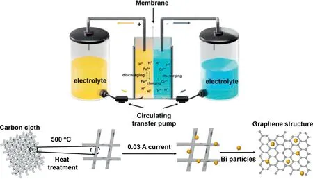
Fig.1.The working principle and schematic diagram of electrode preparation for ICRFB.
The morphologies of composited carbon cloth samples are shown in Fig.2.The electrode made by TCC demonstrated a threedimensional structure, which has ordered carbon fibers and large pores.There were some shaped grooves and defects on the carbon fibers (Fig.2a).Fig.2b shows Bi/TCC prepared through electrochemical deposition.On the surface of the carbon fibers, several particles could be seen, and the size of these particles varied from 200 nm to 400 nm.Simultaneously, TEM was used to observe particles on the electrode surface (Fig.2c).HRTEM images demonstrated that Bi particles on the decorated electrode have good crystallinity.As shown in Figs.2d and e, the relative lattice spacing was measured to be 0.33 nm, and corresponds to the (012) crystal plane of Bi particles (Fig.2f) [42].In addition, the (200) crystal plane of Bi2O3was identified in Fig.2f, which suggests that Bi particles were partially oxidized.To further confirm the substance deposited on the electrode, EDS mapping was used, and these particles were identified as Bi (Fig.S1 in Supporting information).Fig.2g shows Bi was evenly dispersed on the surface of the TCC electrode, indicating that the catalyst was well deposited.The existing defects and the introduction of the Bi catalyst heighten the wettability and specific surface area of the original electrode [37,43], reducing the contact angle of Bi/TCC in comparison to TCC (Fig.S2 in Supporting information).
Fig.3a shows synchrotron radiation diffraction images of different samples.The characterized peak of Bi particles was not evident in the figure, which could be explained by the small amount of added Bi catalyst.The peak value of TCC was higher and sharper than Bi/TCC at around 2.5° It might be indicated that the addition of Bi catalyst affected the crystallinity of TCC.As shown in Fig.3b, there are two peaks located at 2θ≈27° and 49° for the Bi/TCC samples, corresponding to (012) and (110) crystal planes of Bi metal (PDF#44-1246), which can prove that Bi ions convert into Bi metalviaelectrochemical deposition and adhere to the surface of TCC.
In addition, the other peaks at 25° and 44° were distinctive peaks associated with the structure of TCC, corresponding to the crystal planes of (002) and (100) [13].The chemical structure groups of the TCC and Bi/TCC were analyzed by FTIR (Fig.S3 in Supporting information).It was apparent that TCC indicated typical stretching vibration of O–H centering at 3433 cm-1.The other stretching vibrational bands of TCC also included C–H bond at 2197 cm-1and C–N bond at 1633 cm-1.With the introduction of the Bi catalyst, the O–H stretching vibration absorption peak shifted from 3433 cm-1to 3384 cm-1, which might be explained that Bi particles and TCC interact chemically.The elemental composition and the type of bonding structure of prepared samples were further analyzed by XPS as shown in Fig.3c.The C 1s spectrum of TCC shown in Fig.S4a (Supporting information) presents three peaks at 284.8,285.1 and 286.8 eV, which could be associated with C=C, C–C and C–O, respectively.The N 1s spectrum (Fig.S4b in Supporting information) could be observed into two peaks at 400.3 and 401.8 eV,representing graphitic N and pyrrolic N.Fig.S4c (Supporting information) demonstrates two characteristic peaks in O 1s spectrum at around 532 and 533.1 eV, confirming the presence of C–OH and C–OOH.Fig.3d indicts the high-resolution region of C 1s spectrum of Bi/TCC.The C 1s peak could be described by the combination of four peaks: C–C at 285.1 eV, C=C at 284.5 eV, C–O at 286 eV, and O=C–O at 289.2 eV [44].C–C and C=C were the main combinations of carbon in both TCC and Bi/TCC.
The N 1s of Bi/TCC is indicated in Fig.3e, which consists of three peaks of 398.4, 400.3 and 401.5 eV, assigning to graphitic N, pyrrolic N and pyridinic N, respectively [45].The Bi 4f nuclear polarography could be split into two peaks at 160.1 and 165.4 eV(Fig.3f), matched to Bi 4f7/2and Bi 4f5/2which illustrated that these were the characteristic peaks of metal Bi0[3,46].It also showed that the Bi ions in solution were turned into Bi monomers by electrochemical deposition, thus producing a good catalytic effect on the TCC electrode.Meanwhile, there was a slightly positive shift of these peaks of Bi 4f compared to pure Bi0[3], suggesting that Bi catalyst had a strong interaction with the TCC electrode.
Electrochemical tests were conducted to detect reaction activity of Bi/TCC and TCC toward the Fe2+/Fe3+and Cr3+/Cr2+redox couples.The CV curves of Bi/TCC and TCC towards Fe2+/Fe3+and Cr3+/Cr2+redox couples are shown in Figs.4a and b, respectively.From -0.3 V to 1.1 V (vs.SCE) voltage ranges, both Fe2+/Fe3+redox couples in the samples had two distinct peaks in Fig.4a.Compared with TCC, the oxidation/reduction peak current (ipa,ipc) on Bi/TCC were enhanced effectively.Meanwhile, the ratio of reduction and oxidation peak current densities (-ipa/ipc) of Bi/TCC and TCC were 1.072 and 1.049, respectively, which were close to 1 (Table S1 in Supporting information), indicating that both samples had great redox reversibility.Besides, the peak potential separation (△E) increased with the introduction of Bi catalyst, indicating that Bi catalyst is not conductive to ameliorate the electrochemical activity of Fe2+/Fe3+redox reaction.From Fig.4b, there was only oxidation peak of Cr3+/Cr2+redox couple for each sample, which demonstrated that both TCC and Bi/TCC have poor reversibility as negative electrodes.Table S1 (Supporting information) provides the relative value of peak current (I) and peak potential (E).Compared with TCC, Cr3+/Cr2+had a superior oxidation peak current and a lower oxidation peak potential in Bi/TCC.It was indicated that Bi catalyst was beneficial to improve the reactivity of negative electrode by providing a significant number of extra active sites, which provide superior electrochemical performance, leading to an acceleration of the reaction speed [47].

Fig.4.CV curves of samples in 1.2 mol/L FeCl2+1.4 mol/L CrCl3+2.5 mol/L HCl solution with a scanning rate of 10 mV/s at (a) -0.3~1.1 V (vs.SCE) and (b) -1~0 V(vs.SCE).Nyquist plots for 1.2 mol/L FeCl2+1.4 mol/L CrCl3+2.5 mol/L HCl solution at (c) η=0.5 V (vs.SCE) and (d) η=-0.5 V (vs.SCE).

Fig.5.The stable configurations of [Cr(H2O)5Cl]2+ adsorbed on graphite surface,defect graphite, and Bi particles.The respective geometric structure and surface distance are shown in the inset figures.
Figs.4c and d compare EIS spectra of different samples at polarization voltages (η) of 0.5 V and -0.5 V (vs.SCE).Each EIS spectrum was combined with a semicircle and a line, which stand for the high frequency and low frequency ranges, respectively [48].The spectra proved that the redox reactions of Fe2+/Fe3+and Cr3+/Cr2+couples happened on the sample surface and are primarily governed by a combination of both diffusion and charge transfer [49,50].Each Nyquist plot was fitted into an equivalent circuit (Fig.S5 in Supporting information).Rsperforms the ohmic resistance of the solution and electrode, the charge transfer resistance of an electrochemical reaction is represented byRct, and CPE stands for the double-layer capacitance of the interface between electrolyte and electrode, which consists both of CPE-T and CPE-P.W stands for diffusion resistance, and defined parameters as W-R, W-T and W-P.Table 1 displays the relative electrochemical fitted data obtained from Zview.Whenηwas 0.5 V, the values ofRsdecreased as introducing Bi catalyst, which showed a high conductivity.As theRctvalue of increased with Bi catalyst deposition, it was possibly explained that Fe2+/Fe3+redox couple had a low electrochemical activity.Atηis -0.5 V, Bi/TCC had a lowerRsvalue in contrast to TCC, and the value ofRctreduced remarkably, which indicated Bi catalyst had a significant activation effect on the Cr3+/Cr2+redox couple.These results confirmed the electrochemical properties toward the Cr3+/Cr2+redox reaction was prominently enhanced by the introduction of Bi catalyst, which agreed with the results of the CV test.
The calculation is introduced to explain the improvement in performance by density function theory (DFT).From Fig.5, the absorption energy of pristine graphite (0001) was -6.00 eV.There are more stable configurations, when Cr(III) was adsorbed on the defect graphite and Bi particles (001) surfaces with respective adsorption energies of -6.12 eV and -14.00 eV.Both of them were less than the pristine graphite (0001).The energy of adsorbing Cr(III) on the Bi particles surface is 2.33 times higher than on the graphite surface, suggesting that the adsorption configuration of Bi particles was more stable.Besides, the interplay distance between Cr(III) and Bi particles (2.03 ˚A) was shorter than that of graphite (3.60 ˚A), promoting the transport of electrons.The Gibbs free energy was calculated to find out the spontaneity of the adsorption process on the graphite and Bi particles surfaces.The result showed that both of them were less than zero, showing the adsorption process was spontaneous.Furthermore, the Gibbs free energy (ΔG) of Bi particles (-15.50 eV) was lower than that of graphite (-6.34 eV) and defect graphite (-6.38 eV) (Table S2 in Supporting information), which demonstrates the Bi particles surface adsorption of Cr(III) was more easily performed.
The charge density difference for Cr(III) absorbed on the graphite and Bi particles surfaces are displayed in Fig.6.The charge transfer between graphite and the hydrate of Cr mainly occurred on the graphite surface.On the contrary, there existed more charge transfer from Bi particles to the hydrate of Cr(III) especially around the adsorbed water molecules and the Bi particles surface, resulting in strong adsorption.The Bader charge was also analyzed to explain the strong electron transfer.The value of the Bader charge on the Bi particles surface was higher than that of the graphite, and the total charge transfer was 1.21 |e|.Meanwhile,the total charge transfer for graphite and defect graphite were 0.94 and 0.99 |e|, respectively.Detailed simulation information can be found in Figs.S6 and S7 (Supporting information).The result was consistent with the charge density difference, demonstrating that the Bi catalyst transfers more electrons and had high activity compared with pristine graphite, which could provide more active sitesin the reaction.The defect graphite was more suitable for the reaction of Cr(III) than the intact graphite in every aspect.

Table 1 Parameters fitted by Zview.
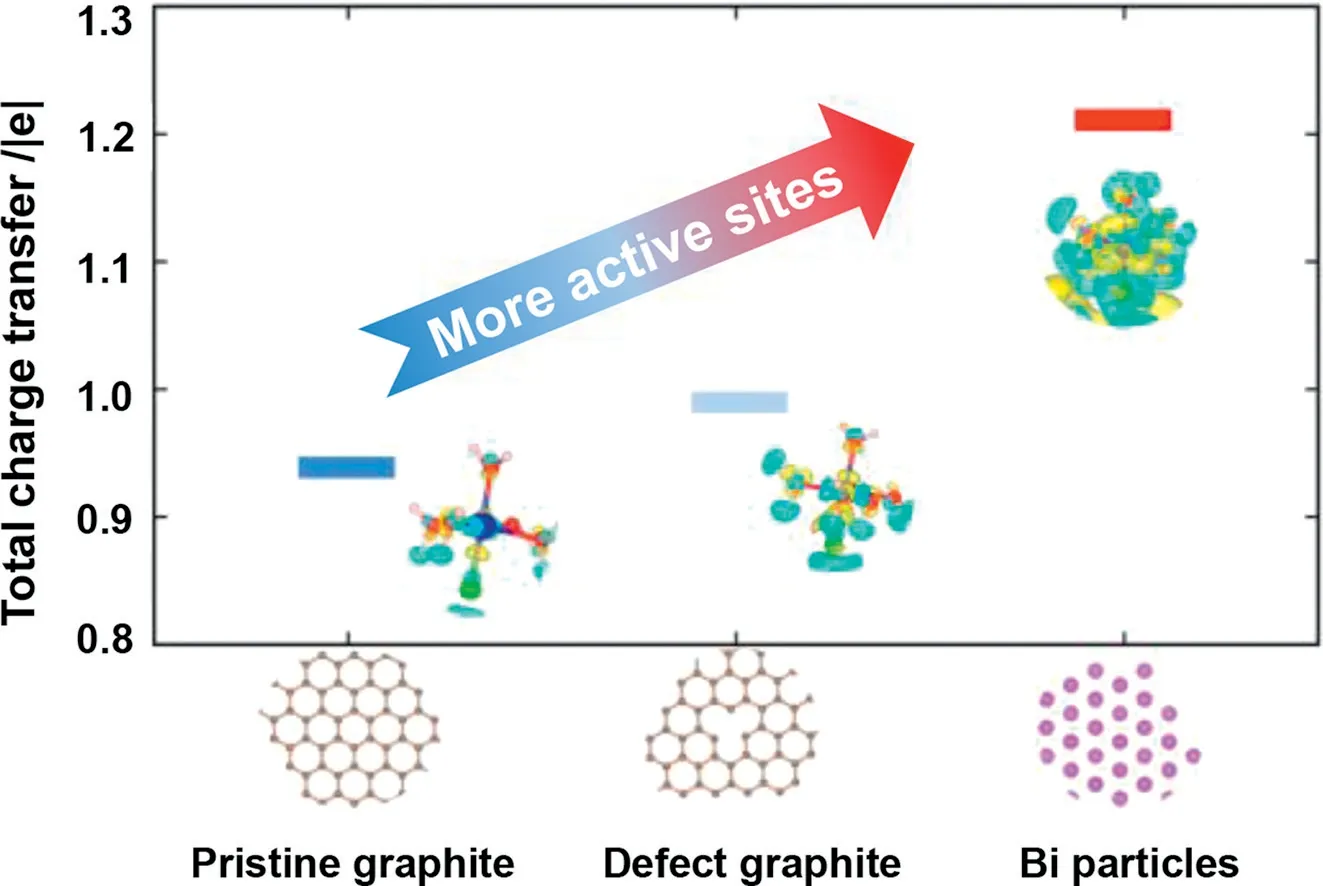
Fig.6.The total charge transfer of Cr(III) adsorbed on graphite surface, defect graphite, and Bi particles surface while the isosurface=0.0008 e/Bohr3.The respective geometric structure and charge density difference are shown in the inset figures.The color yellow represents the charge increase and the color cyan represents the charge decrease.
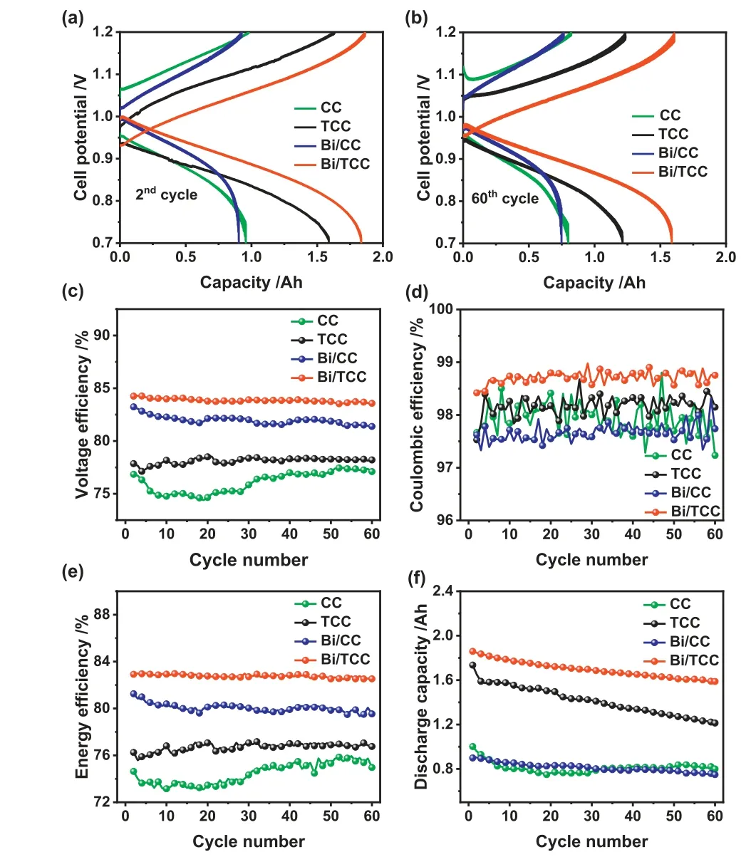
Fig.7.Cell voltage profiles of CC, TCC, Bi/CC and Bi/TCC assembled cells in the (a)2nd and (b) 60th cycle.(c) voltage efficiency, (d) Coulombic efficiency, (e) energy efficiency and (f) discharge capacity of different electrodes assembled cells in 60 cycles at a constant current density of 140 mA/cm2.
Cyclic testing was used to estimate the suitability and stability of single cells.Fig.7 shows the properties of ICRFBs assembled with CC, TCC, Bi/CC and Bi/TCC as electrodes according to the charge-discharge test at 140 mA/cm2.The synergistic effect of defects and the Bi catalyst is one of the helpful treatments to increase the ICRFBs energy efficiency at a higher current density compared to other ICRFBs studies in recent years (Table S3 in Supporting information).The voltage-time curve with a current density of 140 mA/cm2is shown in Fig.S8 (Supporting information).The maximum discharge voltage was found in the Bi/TCC assembled single cell, which could have been caused by defects and the catalysis of the Bi catalyst on the CC surface.From Figs.7a and b,the results illustrated the voltage profiles of cells with these different electrodes at the second and 60th cycles.It could be observed that the single cell with Bi/TCC electrodes exhibited voltage profiles with lower charging and discharging over potentials compared to other cells, demonstrating its superior reaction kinetics.After 60 cycles, a Bi/TCC assembled ICRFB still had a higher capacity under smaller voltage separations compared to other cells,as Bi/TCC electrodes could decrease the electrochemical polarization effectively and keep the stability of the battery [51].Figs.7ce show the ICRFBs performance over the 60 consecutive cycles of the charging and discharging operation.As shown in Fig.7c, the battery assembled with Bi/TCC exhibited a highest average voltage efficiency (VE).The VE value of the cell using Bi/TCC as electrodes can achieve 83.94% after 60 cycles with a constant current density of 140 mA/cm2, 7.78%, 5.7% and 1.97% higher than that assembled with CC, TCC and Bi/CC electrodes, respectively.According to the electrochemical results of the negative electrode and the value of VE, it can be illustrated that the performance of ICRFBs is relative to negative reaction activity.Meanwhile, VE and EE values exhibited similar trends because there was not a clear distinction in CE values among these electrodes assembled cells(Fig.7d).
Fig.7e demonstrates that the single cell had a high EE of 82.77%through defect engineering and Bi catalyst catalyzed, which was 8.45% higher than CC.ICRFBs with different electrodes exhibited good stability after 60 experimental cycles, except CC electrode,indicating all electrodes after treatment could enhance the electrolyte accessibility and adapt to a strongly acidic electrolyte.Furthermore, Fig.7f indicates the discharge capacity of different electrodes assembled cells.The capacity decay rate of an ICRFB utilizing Bi/TCC as electrodes showed superior capacity retention during 60 charge–discharge cycles, which was only 0.23% per cycle,while a single cell utilizing CC as electrodes was 0.5% per cycle.The performance of ICRFBs can be slightly enhanced by Bi/CC,however, the performance of the battery assembled by Bi/CC is inferior to that of the battery assembled by Bi/TCC.The results could prove that Bi catalyst was strongly adhered to the surface of TCC during the cell cycling.The synergistic effect of defect engineering and Bi catalyst can significantly enhance the ICRFBs performance.
In this study, defect engineering was proven as a fantastic approach to govern and control microstructure, which was used to create defect sites on carbon cloth.Furthermore, Bi particles were successfully deposited on the surface of TCC through electrochemical deposition method.The Bi/TCC could provide more active sites compared with pure CC and TCC, which can improve the electrochemical activity of electrodes.Based on the DFT calculations,the hydrate of Cr(III) was prone to adsorb the Bi surface and defect graphite, which formed a more stable configuration and provided more reaction sites than the pristine electrode.It was conducive to facilitate the performance of the Bi catalyst on ICRFBs.According to the further cell test, the EE of a Bi/TCC single cell could achieve 82.77%, which was about 8.5% higher than the battery assembled with CC at a current density of 140 mA/cm2.Meanwhile, the capacity decay rate of the Bi/TCC assembled cell was only 0.23% per cycle, indicating that Bi catalyst can significantly enhance the ICRFBs performance.Therefore, Bi/TCC prepared by defect engineering and electrochemical deposition is an outstanding electrode material that offers a new possibility for the commercialization of ICRFB in the future.
Declaration of competing interest
The authors declare that they have no known competing financial interests or personal relationships that could have appeared to influence the work reported in this paper.
Acknowledgments
This study was supported by the National Natural Science Foundation of China (No.52211530034) and General project of Beijing Natural Science Fund (No.3222018).
Supplementary materials
Supplementary material associated with this article can be found, in the online version, at doi:10.1016/j.cclet.2023.108188.
 Chinese Chemical Letters2023年10期
- Chinese Chemical Letters的其它文章
- Tribute text in memoriam of James N.Seiber (1940–2023)
- Recent advances in MXenes-based glucose biosensors
- Oxidative cyclopalladation triggers the hydroalkylation of alkynes✩
- An integrated supramolecular fungicide nanoplatform based on pH-sensitive metal–organic frameworks
- Probing the effect of nitrate anion in CAN: An additional opportunity to reduce the catalyst loading for aerobic oxidations✩
- Nickel-catalyzed reductive coupling reaction of monofluoroalkyl triflates with alkyl carboxylic acids toward the synthesis of α-alkyl-α-fluoro-alkylketones✩