
A Single Feasibility Study of System Multi-feature Analysis and Evaluation Tool Based on AADL Model
2024-01-10 01:54FENGGuangdingMENGBoXIANGYangkui
FENG Guangding, MENG Bo, XIANG Yangkui
(PLA Unit 32382, Wuhan 430000, China)
Abstract:The tool for analyzing and evaluating system characteristics based on the AADL model can achieve real-time, reliability, security, and schedulability analysis and evaluation for software-intensive systems. It provides a complete solution for quality analysis of real-time, reliability, safety, and schedulability in the design and demonstration stages of software-intensive systems. By using the system′s multi-characteristic (real-time capability, reliability, safety, schedulability) analysis and evaluation tool based on AADL models, it can meet the software non-functional requirements stipulated by the existing model development standards and specifications. This effectively enhances the efficiency of demonstrating the compliance of the system′s non-functional quality attributes in the design work of our unit′s software-intensive system. It can also improve the performance of our unit′s software-intensive system in engineering inspections and requirement reviews conducted by various organizations. The improvement in the quality level of software-intensive systems can enhance the market competitiveness of our unit′s electronic products.
Keywords:IMA; multi-feature analysis; AADL; analysis tool
1 Introduction
In response to the high requirements for reliability and security of software-intensive systems, the system multi-characteristics analysis and evaluation tool based on the AADL model can support the analysis of system quality that meets standard requirements for various models of embedded systems. It supports the system development work to meet the system quality assurance requirements specified in "Haoding No. 4 Document," GJB 900A, GJB 102A, GJB 142, DO-178B/C, GJB 5000, etc[1]. Its functions are summarized as follows.
1) In the system scheme design phase, based on the system′s requirement specifications, preliminary design, and detailed design documents, the software and hardware architecture of the system can be modeled[2]. By analyzing the system′s non-functional requirements, the real-time, reliability, security, and time properties of the system components can be established as parameters in the system′s extended AADL model, providing input for the analysis and evaluation of non-functional attributes during the system verification process.
2) In the system scheme demonstration phase, the system can be demonstrated based on the system architecture model and the model established for non-functional attributes in the system design phase.
(1) Real-time analysis and evaluation: Based on the input of component execution time and network latency in the AADL model, and dynamic simulation of interface relationships between software and hardware components and the system′s execution task paths[3], the real-time analysis of the system can help analyze the impact of different system architectures on system real-time performance under specified tasks and demonstrate the system design scheme.
(2) Reliability analysis and evaluation: The system′s reliability can be analyzed based on the basic reliability of system components and the dynamic operating parameters of the system during the construction of the system′s AADL model. This helps estimate the system′s reliability indicators in the early stages and demonstrate the optimization design of the system for different design schemes[4].
(3) Safety analysis and evaluation: Based on the safety analysis parameters of various software and hardware components inputted in the system′s AADL model, the safety of the system′s software and hardware interfaces and operations can be dynamically simulated to perform architectural safety analysis[5].
(4) Schedulability evaluation: Based on the schedulability analysis parameters of various software and hardware components inputted in the system′s AADL model, such as scheduling period and frequency, the schedulability analysis of the software time dimension arrangement and configuration of the system can be conducted[6].
3) In the configuration phase, based on the system′s final actual test data, operational data, actual system hazard analysis report, and relevant quality test results, the system′s AADL model can be built to analyze and evaluate the system′s real-time capability, reliability, safety and schedulability[7]. This serves as an auxiliary analysis tool for the final configuration, improving the quality of the configuration files.
2 Device composition
The analysis and evaluation tool for system multi-characteristics (real-time, reliability, safety, and schedulability) based on the AADL model is mainly composed of the subsystems of AADL-based system modeling, real-time analysis, reliability analysis, safety analysis, and schedulability analysis[8]. The functions of each subsystem include the following.
1) AADL-based system modeling function provides the elements of software and hardware system modeling based on the AADL language standard, which can model the system′s architecture and dynamic configuration, provide extensions of AADL parameters for analyzing the system′s real-time, reliability, safety, and schedulability, enabling modeling of the system′s non-functional properties. It integrates the system′s functional and non-functional models[9].
2) Real-time analysis and evaluation function based on AADL architecture model through model-driven modeling methods and inputs of system execution task chains required for real-time analysis, fast analysis results can be obtained[10]. It includes the following sub-functions.
(1) Establish a system execution task model: Model the system′s execution tasks from the aspects of task input and task execution.
(2) Display real-time parameters during the modeling phase, allowing modification or verification of the real-time parameters, providing a complete visual process for real-time analysis.
(3) Perform real-time analysis for different execution tasks. Based on the established execution task model, simulate and obtain real-time analysis evaluation results for different execution tasks.
3) Reliability analysis and evaluation function based on AADL architecture model[11]
(1) Establish a system execution task model: Model the system′s execution tasks from the aspects of task input and task execution. Display reliability evaluation related parameters during the modeling phase and allow modification or verification of the reliability parameters, providing a complete visual process for reliability analysis and evaluation.
(2) Perform reliability analysis for different execution tasks. Based on the established execution task model, simulate and obtain reliability analysis results for different execution tasks. Combine the established system architecture model with the system configuration model. Simulate and obtain the reliability analysis and evaluation results of the system architecture.
4) Safety analysis and evaluation function based on AADL architecture model[12]
(1) Display safety evaluation related parameters during the modeling phase, allowing modification or verification of the safety parameters, providing a complete visual process for safety analysis and evaluation.
(2) Combine the established system architecture model with the system configuration model. Simulate and obtain the safety analysis and evaluation results of the system architecture.
5) Schedulability analysis and evaluation function based on AADL architecture model[13]
(1) Display schedulability evaluation related parameters during the modeling phase, allowing modification or verification of the schedulability parameters, providing a complete visual process for schedulability analysis and evaluation.
(2) Combine the established system architecture model with the system configuration model. Simulate and obtain the schedulability analysis and evaluation results of the system architecture.
3 The analysis and evaluation tool has the following social and economic benefits
1) Quality attribute requirements that meet the standard and design are integrated: Provide a quality attribute analysis framework and process that meet the standard requirements[14]. Using model-driven analysis methods, based on the system′s architectural model and system dynamic configuration model, drive the analysis of quality attributes, covering real-time performance, reliability, security and schedulability, integrating the real-time performance, reliability, security and schedulability of the system with the design process.
2) Model and data-driven technology for analyzing quality attributes of software-intensive systems: Adopt model-driven technology, draw on the MDA concept, reuse historical quality attribute data of components, and utilize formal model transformation mechanisms to fully explore modeling methods for real-time performance, reliability, security and schedulability of the system, and identify complex quality risks such as interface data faults, functional concurrency, and software-hardware coupling in the requirements and design phases[15].
3) Automated system analysis and verification, reducing costs by 90%: The tool can quickly analyze the indicators of the system′s real-time performance, reliability, security and schedulability through model-based automated transformation, reducing costs by more than 90% compared to manual analysis. The tool provides real-time statistical analysis results and generates software quality analysis reports that meet the development requirements.
4 Tool application cases
There are a total of 6 models in the example of system modeling and analysis for this project. They are divided into three groups to verify the differences in system quality characteristics of different architectures under three configurations of the DIMA system.
The first group of modeling discusses the architectural transformations caused by network topology (reliability, security), as shown in Figure 1 - Figure 3. In the network composition of architecture 1-1, the connection method of the switches is different from architecture 1-2. Architecture 1-1 is a fully redundant architecture solution, with each peripheral device and module partition connected to two switches. If one switch fails, communication can continue through the other connected switch[16]. Architecture 1-2 does not have redundancy design for peripheral devices, but the modules are still designed with redundancy. It also increases the interconnection in the original scale of switch configuration.

Figure 1 Architecture 1-1: Fully redundant architecture scheme
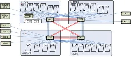
Figure 2 Architecture 1-2: Peripheral redundancy free design architecture scheme
Each module in architecture 1-1 and architecture 1-2 needs to be further subdivided, such as module D1 (which covers the basic configuration of refactoring).
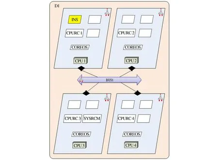
Figure 3 Architectures 1-1 and architecture 1-2: Module configuration scheme
The second group of modeling discusses the architecture transformation (real-time, reliability, security) caused by application processing modes, as shown in Figure 4 - Figure 7. In architecture 2-1, the sensor processing function is placed in the backend, which runs in the task area function. All six applications are processed in the task processing area, and the sensor management area is not responsible for radar, optoelectronics, and electronic warfare. In architecture 2-2, the sensor processing area is responsible for the application processing of radar, photoelectric and electronic warfare, and is in the same module. The task processing area only has fusion, fire control, and suspended object management. Compare the different real-time, reliability and security situations brought by two different architectures of the system[17].
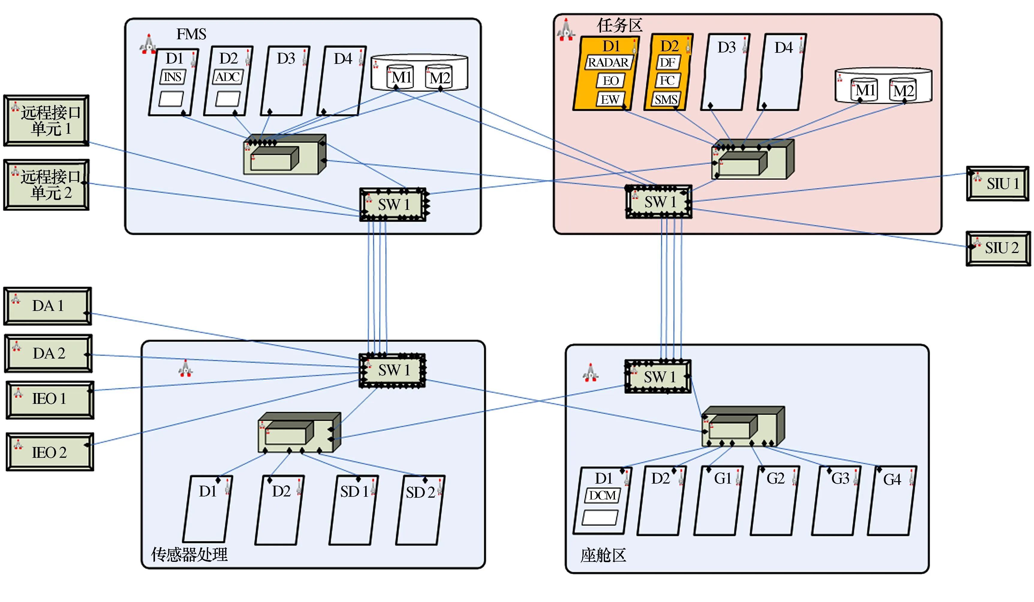
Figure 4 Architecture 2-1: Task processing area centralized processing scheme

Figure 5 Architecture 2-1: Module configuration scheme

Figure 6 Architecture 2-2: Partition processing scheme for sensor processing area and task processing area
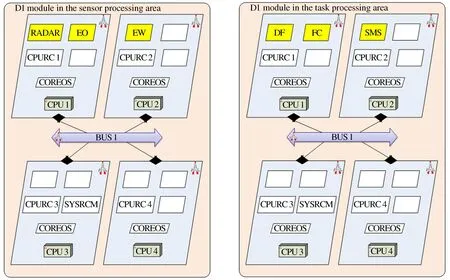
Figure 7 Architecture 2-2: Module configuration scheme
The third group of modeling discusses the architectural changes caused by application partition configuration (real-time, reliability, security). The architecture transformations involved in this section are all based on the transformation of partition application configuration based on architecture 2-2. In architecture 3-1, the task area only has applications in a single module, and is divided into three sub architectures based on different configuration schemes for the same and different partitions of the application in a single module, as shown in Figure 8. In architecture 3-2, the task processing area has dual modules with applications, and is divided into two sub architectures according to different configuration schemes applied in the same and different partitions of module D1, which contains two applications, as shown in Figure 9 - Figure 14.

Figure 8 Architecture 3-1: Application of single module in task area
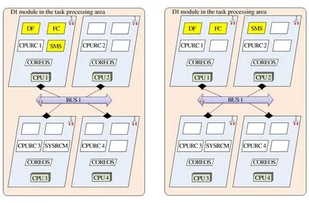
Figure 9 Architecture 3-2: Module configuration schemeFigure 10 Architecture 3-3: Module configuration scheme

Figure 11 Architecture 3-4: Module configuration scheme
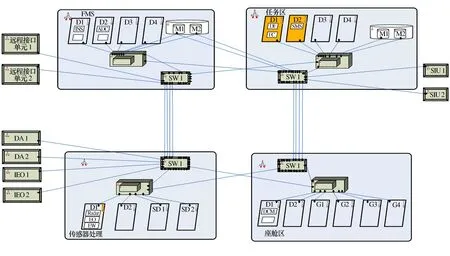
Figure 12 Architecture 3-4: Task processing area dual module application

Figure 13 Architecture 3-4: Module configuration scheme
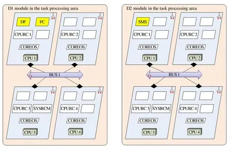
Figure 14 Architecture 3-5: Module configuration scheme
5 Model conversion
Firstly, conduct AADL modeling of the system, fully following architecture 3-4, with a dual module application architecture in the task processing area. Each task area has 4 modules, with 4 partitions within each module. The applications on the partitions run on the operating system of the partition where the application is located. Each module has a multi-core operating system: the specific modeling process is divided into four zones[18]: Task zone, FMS zone, cockpit zone, and sensor processing zone. Each module is divided into four functional modules represented by D, with the task area, FMS area, and two large capacity storage modules represented by M. The system module has an internal bus represented by Bus, a partitioned operating system, and an internal application. Use the OSATE modeling tool for modeling. The established AADL model diagram is as follows:
6 Analysis of application cases (fire control attack task flow)
1) The radar receives radar echoes, processes signals and data, generates target information, and sends it to the information fusion processing module.
2) The photoelectric aperture receives detection signals, performs signal processing and data processing, generates target information, and sends it to the information fusion processing module.
3) Electronic warfare equipment receives radar electronic support information, performs target feature localization, analyzes target radiation sources, obtains target information, and sends it to the information fusion processing module.
4) The inertial navigation device sends its own position, attitude and angle information to the fire control processing module and display control management module.
5) The information fusion processing module integrates multi-source sensor data to achieve fusion processing of radar, optoelectronic, and electronic warfare target detection information, evaluates and sorts target information, and sends the results to the display control management module and fire control processing module.
6) The hanging object management module performs weapon power-up and self inspection, automatically binds the attack target number based on fire control information, and sends the binding information to the display control module.
7) The display control module processes and displays allowable transmission information.
8) The pilot presses the weapon launch button, and the cockpit control module collects the weapon launch signal.
9) The cockpit control module outputs weapon emission signals to the fire control processing module for fire control calculation.
10) The fire control processing module determines whether the missile launch conditions are met. If they are met, the launch meet signal is output to the suspended object management module.
11) The suspension management module completes weapon launch control.
Fire control attack task information flow diagram is shown in Figure 15.
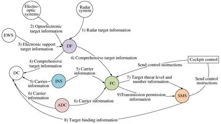
Figure 15 Fire control attack task information flow diagram
7 Analysis of system architecture evaluation results
Following the modeling research method of this project, a total of 9 architectures proposed in the modeling phase, were evaluated and analyzed for real-time performance, reliability and security[19].
7.1 Real time evaluation analysis
The real-time comparative analysis model of this project is included in the entire system architecture, including a comprehensive task processing area (including several DIMA modules with several partitions on which application processes reside), a TTE network switch, RDC, peripheral emulator, simulated cockpit and global state simulation/monitor.
The communication between the simulated cockpit, global situation simulation/monitor and the integrated task processing area needs to go through a layer of network conversion, converting Ethernet through RDC to TTE network to achieve communication with the partitions.
The millimeter wave radar simulator is interconnected with the TTE bus to achieve communication with the integrated task processing area.
In the process of analyzing the real-time performance of system architecture, in order to obtain the optimal architecture, changes are made to the architecture, and the total execution time under typical tasks is analyzed separately. The architecture with the least time is the optimal.
Due to the fact that the architecture involved here did not consider the situation where a partition resides in multiple applications when designing partitions within the DIMA module, there is no scheduling issue for processes within the partition. For scheduling between partitions within the module, execute based on the configured time slices for each partition to achieve time and memory isolation[20].
Three typical architectures were analyzed: three partitions in one module, two modules, and three modules. The real-time performance calculation results of three partitions in one module, two modules, three modules were respectively: 350 ms, 890 ms, and 840 ms. Three partitions communicate within the same module, resulting in the best real-time performance calculation results. Among the two modules, the calculation results of the three partitions considering the real-time performance of cross module calls are lower than those of the three partitions in the same module. However, among the three modules, the data communication speed of the switch is better than that of the inter partition communication due to the inter partition communication passing through the switch, so the real-time calculation results are better than the calculation results of three partitions in two modules.
7.2 Reliability evaluation analysis
Conduct reliability analysis on the architecture of this project. The architecture transformation caused by the network topology of the 1-1 and 1-2 models resulted in a reliability calculation result of 0.966 85 for 1-1, and 0.971 6 for 1-2. Due to the dual redundancy design of switches and peripherals relative to 1-1, 1-2 is equivalent to parallel connecting peripherals and switches in the architecture in terms of reliability calculation, thus improving the reliability of the system.
Based on the architecture calculations of 2-1 and 2-2, the reliability calculation result for 2-1 is 0.986 8, while the reliability calculation result for 2-2 is 0.952 0. After analyzing the architecture, we can see that six applications in 2-1 are all processed in the task processing area, and in 2-2, the sensor processing area is responsible for the application processing of radar, photoelectric and electronic warfare and is in the same module. The task processing area only has fusion, fire control, and suspended object management. The analysis shows that the reliability of the system with applications in the same module is higher than that of the system with applications distributed in cross functional areas and cross module areas[21].
For 3-1 to 3-5, the calculated system reliability results are respectively 0.967 4, 0.952 0, 0.952 0, 0.956 4, 0.956 8. After analyzing the architecture of 3-1~3-5, the reliability applied in the unified module of the same functional area should be higher than that applied in different modules of different functional areas.
7.3 Safety assessment analysis
Conduct security analysis on the architecture of this project, and the evaluation results of the security analysis from 1-1 are {(0.145 2, catastrophic), (0.179 7, hazardous), (0.231 2, major), (0.263 5, minor), (0.180 4, no effect)}. The safety analysis and evaluation results of 1-2 are {(0.155 6, catastrophic), (0.179 3, hazardous), (0.215 3, major), (0.279 4, minor), (0.170 4, no effect)}. Due to the dual redundancy design of the switch module and peripheral module in the architecture 1-2 system in the security analysis, the severity and likelihood of module failure consequences of the switch module and peripheral module in the 1-2 system were adjusted in the setting of security evaluation attributes, and the likelihood of these two modules being set relatively low. Therefore, in the final system security evaluation results, the security evaluation results of architecture 1-2 are biased towards two levels: no effect and minor.
For architecture 2-1 and 2-2, the calculated security evaluation results are {(0.092 4, catastrophic), (0.124 7, hazardous), (0.131 5, major), (0.463 5, minor), (0.187 9, no effect)} and {(0.082 1, catastrophic), (0.134 7, hazardous), (0.171 5, major), (0.478 5, minor), (0.040 8, no effect)}, respectively. These two sets of calculations adopt the fuzzy set of basic security for components. A relatively optimistic evaluation result, And because of the 2-1 architecture, the sensor processing area is responsible for the application processing of radar, photoelectric and electronic warfare, and is in the same module. However, in the task processing area, only fusion, fire control, and suspension management are within their respective functional areas, so a higher security level is set in the construction of the basic safety fuzzy set of components. Therefore, the safety evaluation results of architecture 2-2 are better than architecture 2-1.
For architecture 3-5, the calculated security evaluation results are {(0.112 1, catastrophic), (0.124 7, hazardous), (0.131 5, major), (0.423 1, minor), (0.208 6, no effect)}, {(0.102 6, catastrophic), (0.114 7, hazardous), (0.154 8, major), (0.423 1, minor), (0.204 8, no effect)}, {(0.162 2, Catastrophic), (0.124 7, hazardous), (0.131 5, major), (0.323 1, minor), (0.258 6, no effect)}. The three computing methods also use optimistic evaluation results in the construction of the basic security fuzzy set of components. Because these three architectures are all applied to the same module, the security level calculation results are similar. In the evaluation of the 3-4 and 3-5 architectures, relatively neutral evaluation parameters were used, and the calculation results were {(0.165 4, catastrophic), (0.176 7, hazardous), (0.198 7, major), (0.263 1, minor), (0.196 1, no effect)} and {(0.166 9, catastrophic), (0.174 7, hazardous), (0.188 5, major), (0.263 1, minor), (0.208 68, no effect)}.
However, due to the more complex architecture of 3-5, there will be more paths analyzed in the security assessment, resulting in an average of the results during the synthesis process. The difference in the security level evaluated according to each level will be smaller.
8 Conclusions
The modeling research method evaluates and analyzes the real-time, reliability and security of the system architecture proposed in the modeling stage, which can quantify these characteristic analysis indicators and derive the priority order of these architectures.
However, this analysis tool must have parameter input for characteristic analysis before obtaining these quantitative results, and these parameters are difficult to obtain accurately, which will cause certain result errors, and these characteristic analysis is based on the AADL model built by Osate software, and the model can not accurately replicate the actual complex system, mainly abstract the binding relationship of software and hardware, and then generate an analysis model.
 International Journal of Plant Engineering and Management2023年4期
- International Journal of Plant Engineering and Management的其它文章
- Influence of Section Size of Telescopic Boom on Stability
- The Topology Optimization Under the Static Loads
- Study on Development of Light Aluminum Step by Using Finite Element Analysis