
Study on Development of Light Aluminum Step by Using Finite Element Analysis
2024-01-10 02:00WUJianlong
WU Jianlong
(KONE Elevator Co., Ltd., Kunshan 215300, Jiangsu, China)
Abstract:In order to ensure the safe operation of the escalator, the step as a part of transporting passengers, the design will consider a high safety factor, which will increase the weight, the manufacturing cost, and the energy consumption of the steps band operation. Therefore, in order to reduce the weight and ensure the strength and stiffness of the step, through the optimization design, the number of reinforcing rib supports of the step tread plate and riser plate is increased, and the thickness of the step tread plate and riser plate is moderately reduced, so as to achieve the purpose of reducing the weight of the step and reducing the manufacturing cost and operating energy consumption. Through the finite element analysis and testing of the new type step design, Its strength and stiffness fully meet the requirements of GB 16899-2011 and EN 115-1: 2017 standards, and the breaking force also meets the industry standards, so that the manufacturing and operating costs of the product can be reduced to improve the competitiveness of the product market.
Keywords:light aluminum step; development; finite element analysis
1 Introduction
As a kind of special equipment for efficient transportation of passengers, escalators have been widely used in various public buildings. How to provide a cost-effective escalator equipment has become a key factor for various escalator manufacturers to compete and develop and win market order share.
The step is an important assembly part of escalator, which is used in a large amount on each escalator, so the procurement cost is high. If we develop light step and reduce the weight by using optimization design and finite element method for analysis to ensure that the strength, stiffness and breaking force of the step meet the requirements, then the manufacturing cost and operating cost of the product will be reduced. Thus, to meet customer needs to the maximum extent, and reduce procurement costs and operating costs under the premise of ensuring the same quality.
2 Material and structure of step
2.1 Material
The escalator step are divided according to the material, there are two kinds of aluminum step and stainless steel step, aluminum step are manufactured by die-casting molding, stainless steel step are manufactured by parts assembly, because aluminum alloy have the advantages of good corrosion resistance and low density, so the proportion of customers choose to use is larger, the general use rate is about 90% to 95%. Therefore, the aluminum step need to be optimized and improved.
The aluminum step used must be Al-Si EN AB 44300 according to DIN EN 1676[1](allowed tolerance max. Cu 0.3%) or YL102-1(JZ-102) material, The chemical composition of die-cast aluminum alloy is shown in Table 1.
As YL102-1(JZ-102) is fine-tuned on the basis of the GB/T 15115-2009[2]YL102 for some element content, the mechanical property parameters of YL102-1(JZ-102) die-cast aluminum alloy refer to the mechanical property parameters of GB/T 15115-2009 YL102, as shown in Table 2.

Table 2 YL102 Mechanical property parameters of die-cast aluminum alloy
2.2 Structure
The steps are supported by four rollers on the guide rail, two step rollers and two connectors are connected to the chain roller, and the chain drives the step to run to achieve the transport of passengers. The transport principle of the escalator is shown in Figure 1.

Figure 1 Principle diagram of escalator transport
The step body structure is composed of tread plate, riser plate, connecting support frame and reinforcing rib, as shown in Figure 2.

Figure 2 The structure of the step body
The tread plate is the part where the passenger stands, the riser plate is the contact point where two adjacent steps run in engagement, the connecting support frame is used to fix the two plates into a whole that can withstand external forces, and the reinforcing rib is used to increase the strength and stiffness of the step body. The steps are designed into such a structure to ensure the safety of passengers when the escalator is running.
3 Optimization design
For the all types of escalators produced by the same company, the steps are a common part. According to the scope of GB 16899-2011 and EN 115-1: 2017 standards[3-4], the steps have three specifications of width 1 000 mm, 800 mm, 600 mm, which is based on the number of standing passengers,and considering the geometric dimensions of the human body. The structural dimensions of its crosssection are the same, and it is designed according to the maximum load generated by the number of passengers defined by the width of each step, and the corresponding maximum elastic deformation and minimum breaking force of the step are specified.
As the step is a common part of the escalator, for the same width of various changes in the design of the step, to have universality and interchangeability, so its shape size, interface installation size and the engagement size of the tread plate and riser plate tooth shape can not be changed in the optimization design, change the design can only be carried out on other dimensions of its structure. According to the structure size and load performance of the original design of the 11.7 kg/step, the thickness of the tread plate and riser plate of the step is optimized, and the number of reinforcing bars of the tread plate and riser plate is increased. This new structure reduces the weight of the step to 10.2 kg, and reduces the manufacturing cost and operation energy consumption.
The thickness dimensions of the tread plate and riser plate and the number of reinforcing bars before and after the step optimization design are shown in Table 3, Figure 3 and Figure 4.

Table 3 Comparison data of the tread plate and riser plate thickness
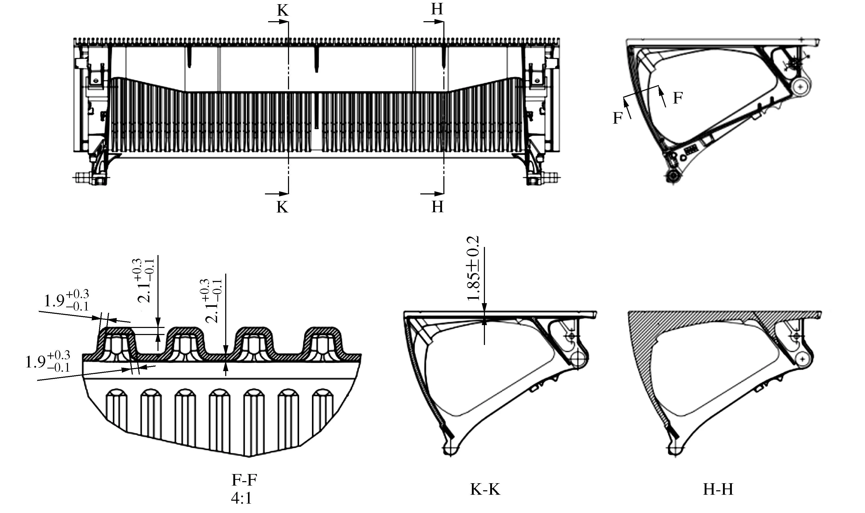
Figure 3 Aluminum step of tread plate and riser plate thickness and reinforcing bar number with a weight of 11.7 kg
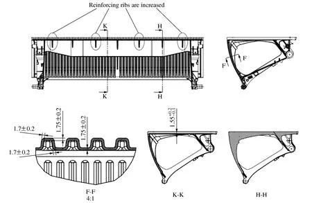
Figure 4 Aluminum step of tread plate and riser plate thickness and reinforcing bar number with a weight of 10.2 kg
4 Finite element model and load cases
Due to the aluminum step manufactured by die casting molding, the strength, stiffness and breaking force of the step must be analyzed and verified after the optimization design. If these requirements are met, the step mold can be modified for sample production. Otherwise, once the load performance test of the step sample is unqualified, the mold may be scrapped, resulting in certain economic losses. Therefore, the finite element method is carried out to analyze the deformation and stress distribution of the new type step after loading.
4.1 Load cases type for step static analysis
Static load analysis of steps according to the GB 16899-2011 and EN 115-1:2017 standards, there are four types of load, breaking force analysis according to industry standards have a load type, these five types of loads applied on the tread surface and riser surface of the force position and direction are shown in Table 4, the applied load model is shown in Figure 5.

Table 4 Load cases type of tread surface and riser surface
Parameter of model:
F1=3 000 N (Load case 1)
F1=20 000 N (Load case 5)
F2=1 500 N (Load case 2 & Load case 3 & Load case 4)
a1=50 mm
b=50 mm
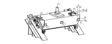
Figure 5 3D model of step static load
4.2 Finite element model
The geometry for the calculation model is designed with PRO/Engineer core 2, shown in Figure 6.

Figure 6 Geometry model of structure
In the calculation model, take solid elements to simulate step component. The element size is lower than 1 mm, and the elements comprised hexahedron and prism[5-9].
The coordinate systems for calculation models are shown in Figure 7. Use one local Cartesian coordinate system (cs:11) to apply boundary conditions for load case 3 and 4, others cases use the global coordinate system.
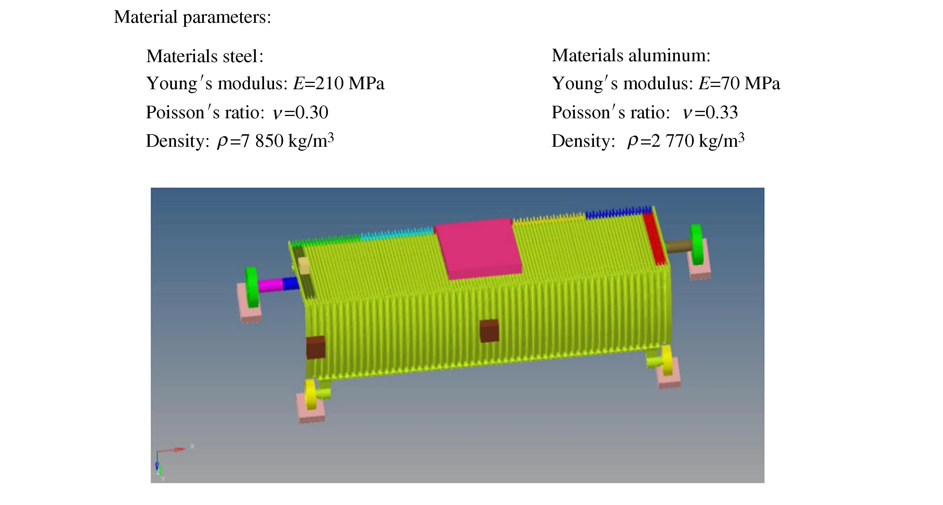
Figure 7 Finite element model
The elements in calculation model are shown in Table 5, the mesh is shown in Figure 7.

Table 5 Used elements in calculation model
5 Result analysis
In the analysis and calculation of load case 1 to load case 4, according to the GB 16899-2011 and EN 115-1:2017 standards, the deflection measured at the tread and riser surface of the step shall be not more than 4 mm. There shall be no permanent deformation. The maximum stress distribution value should not be greater than the yield strength.
The analysis and calculation of load case 5, according to industry standards, the maximum stress distribution value should not be greater than the ultimate tensile strength.
5.1 Load case 1
A single force of 3 000 N (including weight of the plate) applied perpendicular to the tread surface on a steel plate 0.20 m×0.30 m in size and at least 25 mm thick, in the centre of the tread surface of the step. The edge of the plate being 0.20 m long shall be arranged parallel to the front edge of the step, the edge of the plate being 0.30 m long at right angles to the front edge of the step. as shown in Table 4 and Figure 5.
Stiffness of the structure (case 1) is shown in Figure 8.
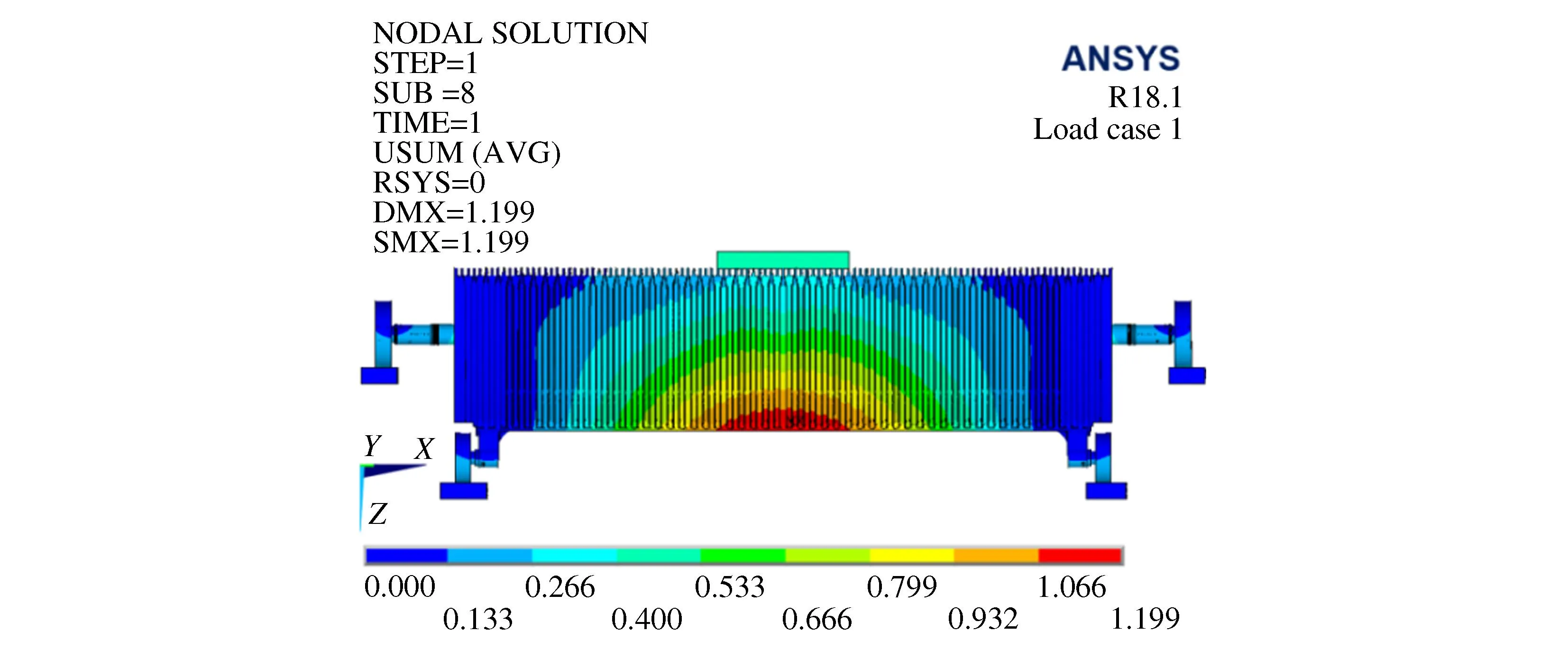
Figure 8 Vector sum deformation distribution for load case 1
Strength of the structure (case 1) is shown in Figure 9.
5.2 Load case 2
A 1 500 N force perpendicular to the tread surface is applied on both sides of the step through a square steel plate with an external dimension of 50 mm×50 mm and a thickness of at least 25 mm, as shown in Table 4 and Figure 5.
Stiffness of the structure (case 2) is shown in Figure 10.
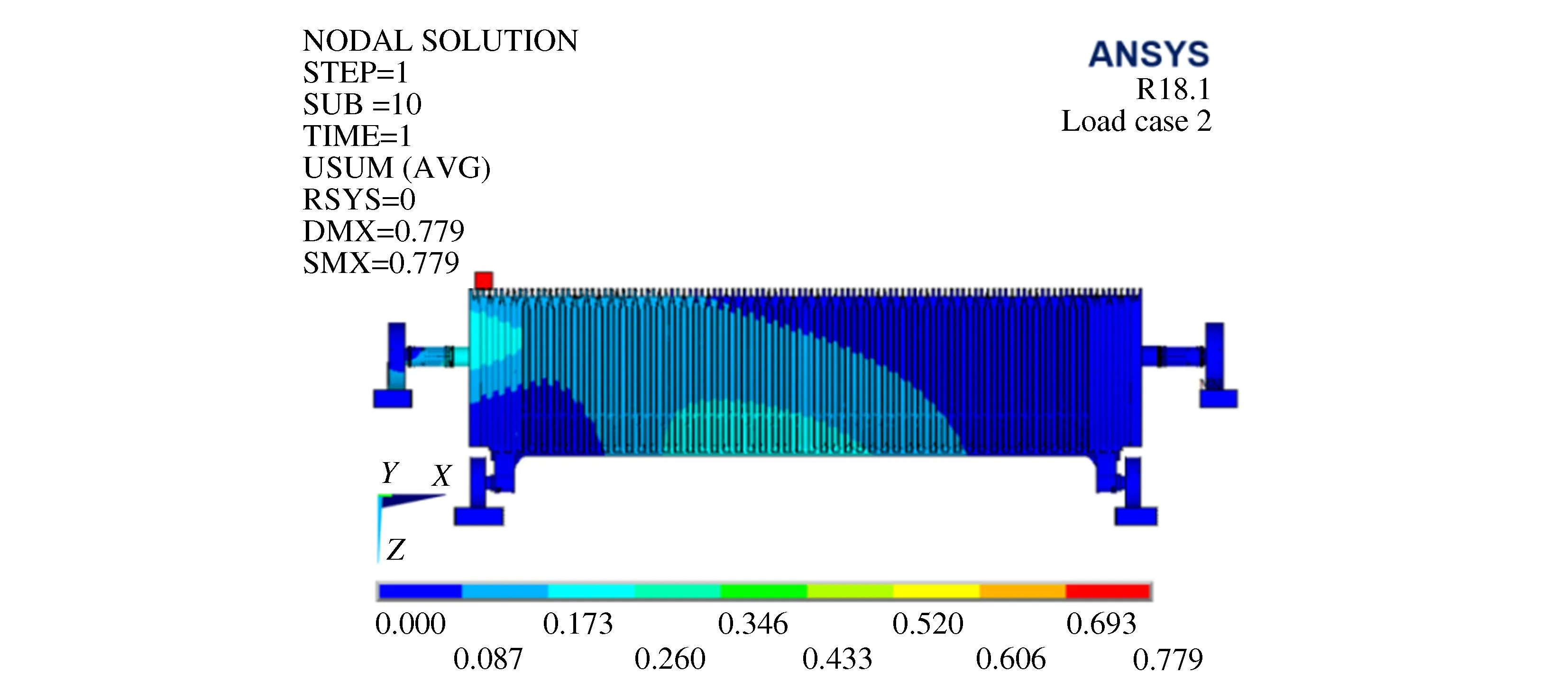
Figure 10 Vector sum deformation distribution for load case 2
Strength of the structure (case 2) is shown in Figure 11.

Figure 11 Von mises stress distribution for load case 2
5.3 Load case 3
A 1 500 N force perpendicular to the riser surface is applied on both sides of the step through a square steel plate with an external dimension of 50 mm×50 mm and a thickness of at least 25 mm, as shown in Table 4 and Figure 5.
Stiffness of the structure (case 3) is shown in Figure 12.

Figure 12 Z-direction (cs 11) deformation distribution for load case 3
Strength of the structure (case 3) is shown in Figure 13.
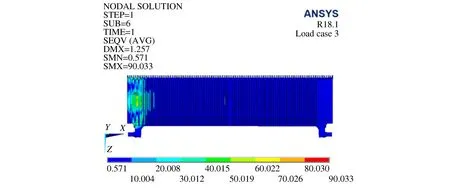
Figure 13 Von mises stress distribution for load case 3
5.4 Load case 4
A 1 500 N force perpendicular to the riser surface is applied in the center of the step riser surface through a square steel plate with an external dimension of 50 mm×50 mm and a thickness of at least 25 mm, as shown in Table 4 and Figure 5.
Stiffness of the structure (case 4) is shown in Figure 14.

Figure 14 Z-direction (cs 11) deformation distribution for load case 4
Strength of the structure (case 4) is shown in Figure 15.
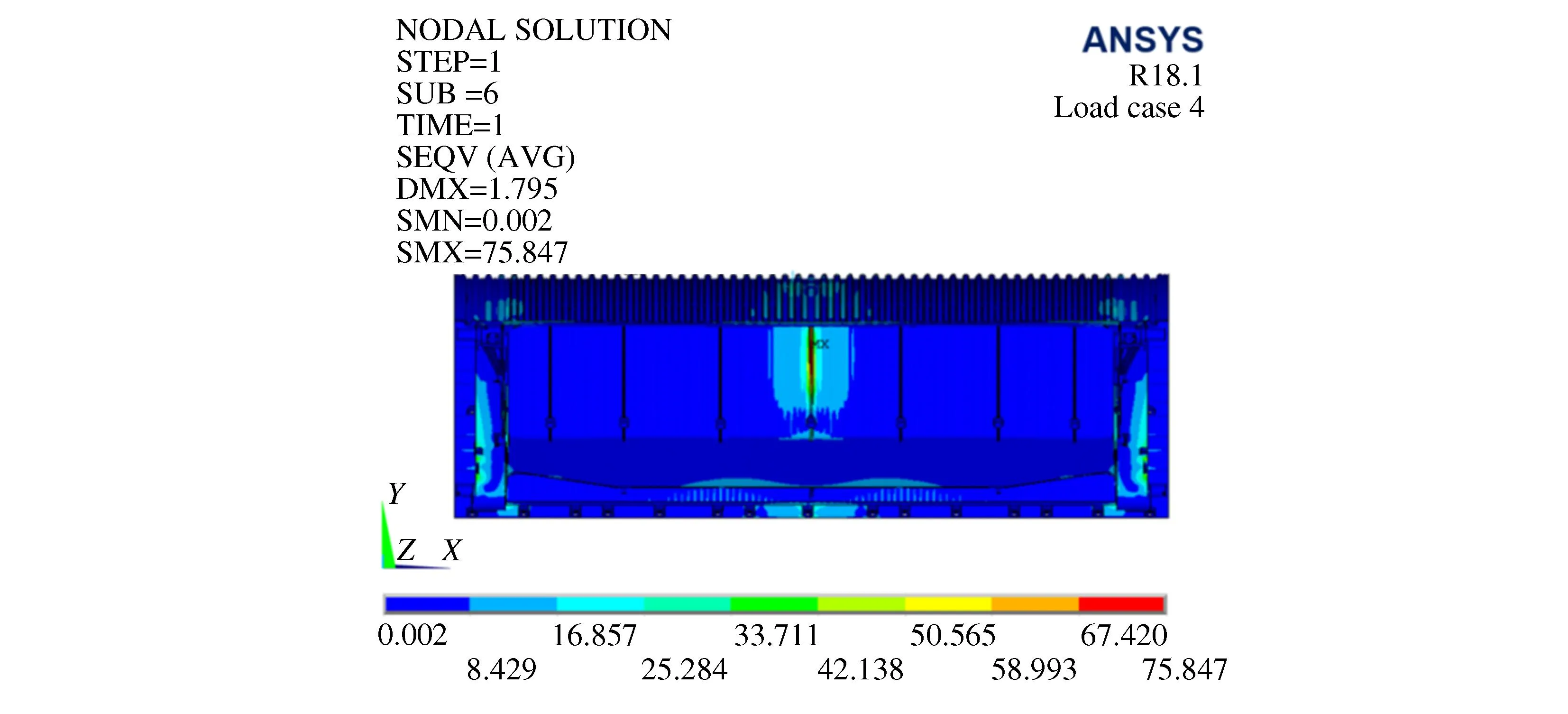
Figure 15 Von mises stress distribution for load case 4
5.4 Load case 5
At the center of the step tread surface, a force of 20 000 N is applied vertically through a steel plate. The size and placement of the steel plate are the same as the force model in load case 1, as shown in Table 4 and Figure 5.
Stiffness of the structure (case 5) is shown in Figure 16.

Figure 16 Vector sum deformation distribution for load case 5
Strength of the structure (case 5) is shown in Figure 17.
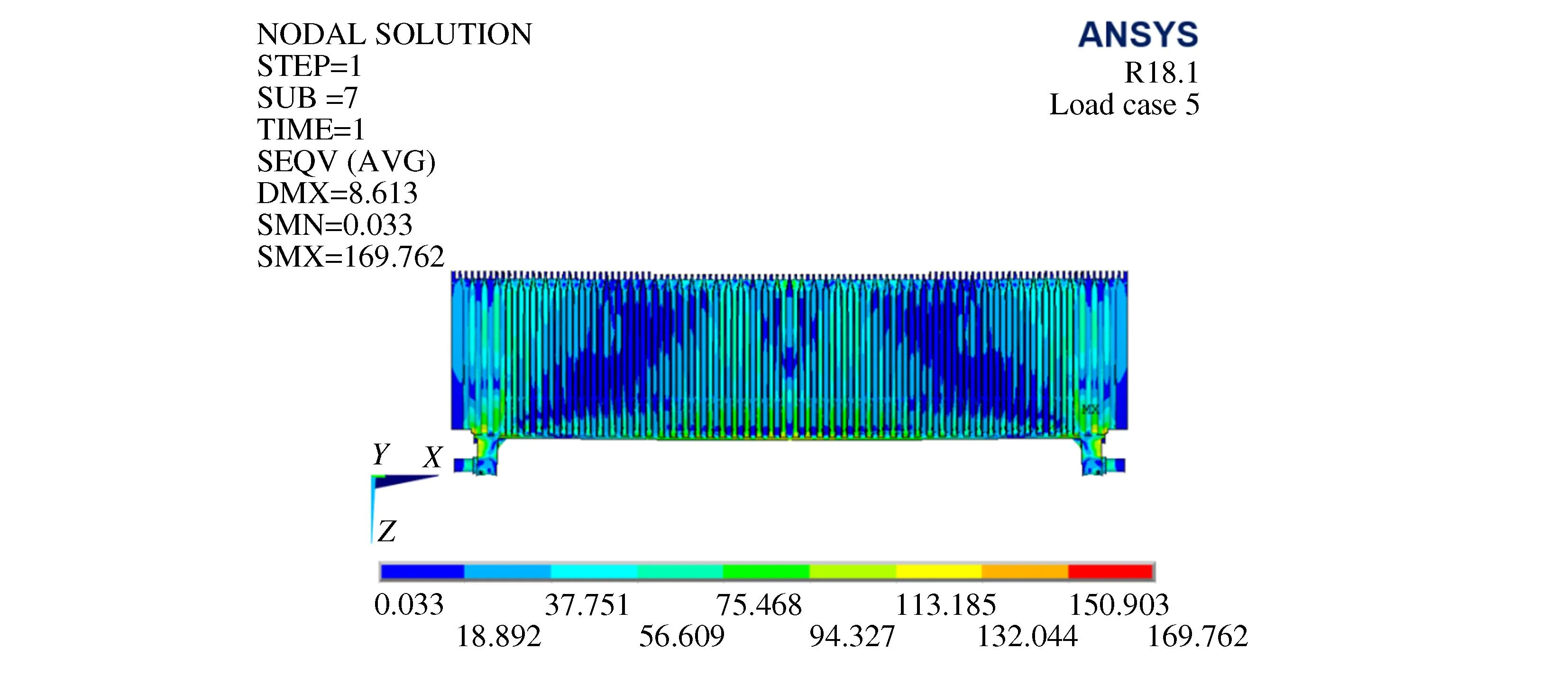
Figure 17 Von mises stress distribution for load case 5
6 Conclusion
By applying five kinds of load cases to the steps and conducting finite element analysis and calculation, the maximum deformation and maximum stress distribution of the steps under various load cases conditions are obtained. The summary data are shown in Table 6.
The results show that the maximum deformation of load case 1, load case 2, load case 3 and load case 4 is 1.794 mm, less than 4 mm, and the maximum stress distribution of 92.974 MPa is less than the yield strength of aluminum alloy material YZAlSi12 (as shown in Table 2), indicating that the deformation generated by the steps is elastic deformation, which meets the requirements of GB 16899-2011 and EN 115-1:2017 standards.
The calculation of load case 5 shows that the maximum stress distribution generated is 169.762 MPa, which is less than the ultimate tensile strength of aluminum alloy material YZAlSi12 (as shown in Table 2). Although the step locally produces small plastic deformation, it does not reach the fracture strain value of aluminum alloy, which is in line with the industry standard.
After the optimized design of the light step, the mold has been renovated, and the die-cast step sample is carried out in the laboratory load test. The obtained data and the finite element calculation results are within the allowable error range, and fully meet the requirements.
Step weight is reduced from 11.7 kg to 10.2 kg, each step reduces the use of 1.5 kg aluminum alloy material, saving material cost of 30 RMB/PC, each escalator according to the average use of 90PC steps, can reduce the manufacturing cost of 2 700 RMB per unit, while reducing the energy consumption of Step band operation, improve the energy efficiency level of the escalator. Thus improve the market competitiveness of the product.
 International Journal of Plant Engineering and Management2023年4期
- International Journal of Plant Engineering and Management的其它文章
- A Single Feasibility Study of System Multi-feature Analysis and Evaluation Tool Based on AADL Model
- Influence of Section Size of Telescopic Boom on Stability
- The Topology Optimization Under the Static Loads