
Influence of Section Size of Telescopic Boom on Stability
2024-01-10 01:54SHEZhanjiaoYAOFenglinWANGJunfeiZHANGYiJIANGJun
SHE Zhanjiao, YAO Fenglin, WANG Junfei, ZHANG Yi, JIANG Jun
(1. Nanchong Vocational and Technical College, Nanchong 637131, China;2. Taiyuan University of Science and Technology, Taiyuan 030024, China; 3. College of Engineering & Technical, Cheng Du University of Technology, Leshan 614000, China)
Abstract:The telescopic boom is the main bearing force component of the crane. The rationality of the design will directly affect the performance of the machine and safety. The telescopic boom is a typical thin-walled plate and shell structure. Its main form of damage is the occurrence of buckling, resulting in decreased carrying capacity, or even a security incident. In order to meet the lifting weight and height, to ensure the stability of the telescopic boom has become a major problem of the designer. There are many factors that affect the critical load of the telescopic boom, including support method, inertia moment, length and material. When the support mode, material and length are determined, the maximum factor affecting the buckling critical load is the inertia moment. In this paper, the influence of the section size on the buckling critical load of the telescopic boom is analyzed by using the inertia moment of section method ande finite element method. And the sensitivity analysis is carried out on this basis. The results of the analysis can provide designers with design reference basis. Then a reasonable cross-sectional size can be used to improve the buckling resistance capacity of the telescopic boom.
Keywords:telescopic boom; buckling stability; sensitivity analysis; section size; finite element
1 Introduction
With good mobility, all terrain crane is widely used in construction, wind power, port and other fields. The telescopic boom is an important actuator of the wheeled crane, which directly determines the maximum lifting height and lifting capacity of crane. With the increasing demand for large lifting height and large lifting capacity, it is an inevitable trend to develop large or super large wheeled cranes, and the telescopic boom will become longer and longer. Modern telescopic boom is generally made of high-strength structural steel, such as WELDOX1100, whose yield strength is as high as 1 100 MPa. A large number of telescopic boom folding accidents show that the cause of failure of telescopic boom is not insufficient strength but instability. The stability of the telescopic boom has attracted great attention from scholars[1-4].
At present, scholars′ research on the stability of the telescopic boom mainly focuses on the solution of the critical force when the telescopic boom is unstable. In the early 1980s, Gu et al. derived the length coefficient of the stability of the crane′s telescopic boom by using the Litz method, which was adopted by the crane design specification GB/T3811-83[5]. Lu et al. used the exact finite element method to give the recursive formula for solving the critical force of the crane′s telescopic boom, which was adopted by the crane design specification GB/T3811-2008[6]. Liu et al. established a variable cross-section telescopic boom model considering the synergistic effect of the support of the cylinder and the lap friction between the telescopic boom, and deduced the formula of the critical force of instability[7]. Yao et al. established the differential equation of the n-stepped telescopic boom based on the longitudinal and transverse bending theory, and deduced the stability recursion formula of the n-stepped telescopic boom by mathematical induction, and gave the numerical solution[8]. Lu et al. used the finite element method to study the dynamic stability of the telescopic boom under axial periodic load[9]. Liu et al. analyzed the stability of the telescopic boom considered the action of non-directional force of the traction rope, and discussed the influence of the ratio of the projection of the traction rope to the boom length on the instability critical force[10].
However, when the support mode, length and material of the telescopic boom are determined, the cross-section shape and size have the greatest influence on the stability of the telescopic boom[11]. At present, the research on the cross section of the telescopic boom mainly focuses on the optimization of the cross section shape and size[12-19]. For example, Wang et al. applied topology optimization to the cross-section design of boom, which effectively improved the mechanical properties of the telescopic boom and reduced the weight of the boom[15]. Liu et al. carried out multi-objective optimization on the cross section of the telescopic boom of the truck-mounted crane, which effectively reduced the mass of the telescopic boom by 24.5%[17]. Shen et al. carried out lightweight optimization on the cross section of the elliptical boom[19]. Liu et al. analyzed the advantages and disadvantages of telescopic boom with different cross sections[20].However, almost no one has studied the influence of section size on the stability of the telescopic boom. In this paper, the influence of cross-section size on stability is studied by using the moment of inertia and finite element method, and the sensitivity of each cross-section size to stability is analyzed, which has important reference significance for the cross-section design of the telescopic boom.
2 Analysis of effect of section size on buckling
In China′s GB/T3811-2008′ Design rules for cranes′, the calculation formulas of the critical force of the telescopic boom below 5 steps in the luffing plane and the rotary plane are given respectively (in the formula, the x-axis coincides with the axis of the telescopic boom, and the y-axis and z-axes are located in the rotary plane, the luffing plane and perpendicular to the axis of the telescopic boom)[11]. The luffing plane of the telescopic boom is shown in Figure 1.
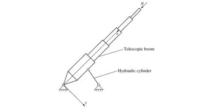
Figure 1 Luffing plane
The critical force calculation formula of the rotary plane is as follows:

(1)
Where: μ1is the length coefficient determined by the support mode of the telescopic boom; μ2is the length coefficient of the variable cross-section telescopic boom; μ3is the length coefficient of the boom considering the influence of the lifting rope; Iz1is the cross-section inertia moment of the basic boom to the z-axis in the rotary plane.
The critical force calculation formula of the variable amplitude plane is as follows:

(2)
Where Iy1is the cross-section inertia moment of the basic boom to the y-axis in the luffing plane.
It can be seen from equation (1) and equation (2) that the influence on the moment of inertia (I) of the section is consistent with the influence on the critical load (N). Therefore, the influence of the section size on the buckling critical load can be obtained by analyzing the influence of the section size on the inertia moment.
The cross section of the telescopic boom is U-shaped, as shown in Figure 2. The U-shaped section can be divided into four parts, of which ① represents the rectangular section of the upper cover plate, ② represents the arc transition section, ③ represents the rectangular section of the web, and ④ represents the semi-circular section of the lower cover plate. The moment of inertia of the entire U-shaped section to the horizontal axis and the vertical axis of the centroid C can be expressed as the sum of the moment of inertia of the four sections to the horizontal axis and the vertical axis, as follows:
Icz=I1z+I2z+I3z+I4z
(3)
Icy=I1y+I2y+I3y+I4y
(4)

Figure 2 U-shaped cross section
According to the resultant moment theorem, the coordinates of the centroid C of the U-shaped section in the coordinate system oyz are as follows:

(5)
(6)
According to the moment of inertia theorem and the size relationship of the U-shaped section, Iczand Icycan be calculated as follows:

(7)
(8)
Where: t is the thickness of the upper cover plate; a is the length of the rectangular section of the upper cover plate; b is the height of the rectangular section of the web; d is the width of the whole section; R0is the inner radius of the arc transition section; R1is the outer radius of the arc transition section; R3is the inner radius of the lower cover plate; R4is the outer radius of the lower cover plate.
3 Influence of size parameters of U-shaped section on moment of inertia of section
In this paper, the influence of the U-shaped section size on the moment of inertia of the section is analyzed in detail, including the increment ΔR of the radius R0in the arc transition, the increment Δt of the thickness t of the upper cover plate, the increment Δδ of the thickness δ of the lower cover plate, the increment Δd of the width d of the whole section and the increment ΔH of the height H of the whole section. The increment of each parameter is brought into the equation (7) and equation (8) respectively, and the corresponding moment of inertia Iczand Icycan be calculated when the parameters change, and the influence of each size parameter on the moment of inertia of the section can be analyzed. The U-shaped section size parameters and incremental values selected in this paper are shown in Table 1, and the corresponding moment of inertia is shown in Figure 3 - Figure 7.

Table 1 Basic size parameters and increments of U-shaped section
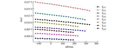
Figure 3 Variation of moment of inertia with increment R

Figure 4 Variation of moment of inertia with increment t

Figure 5 Variation of moment of inertia with increment δ
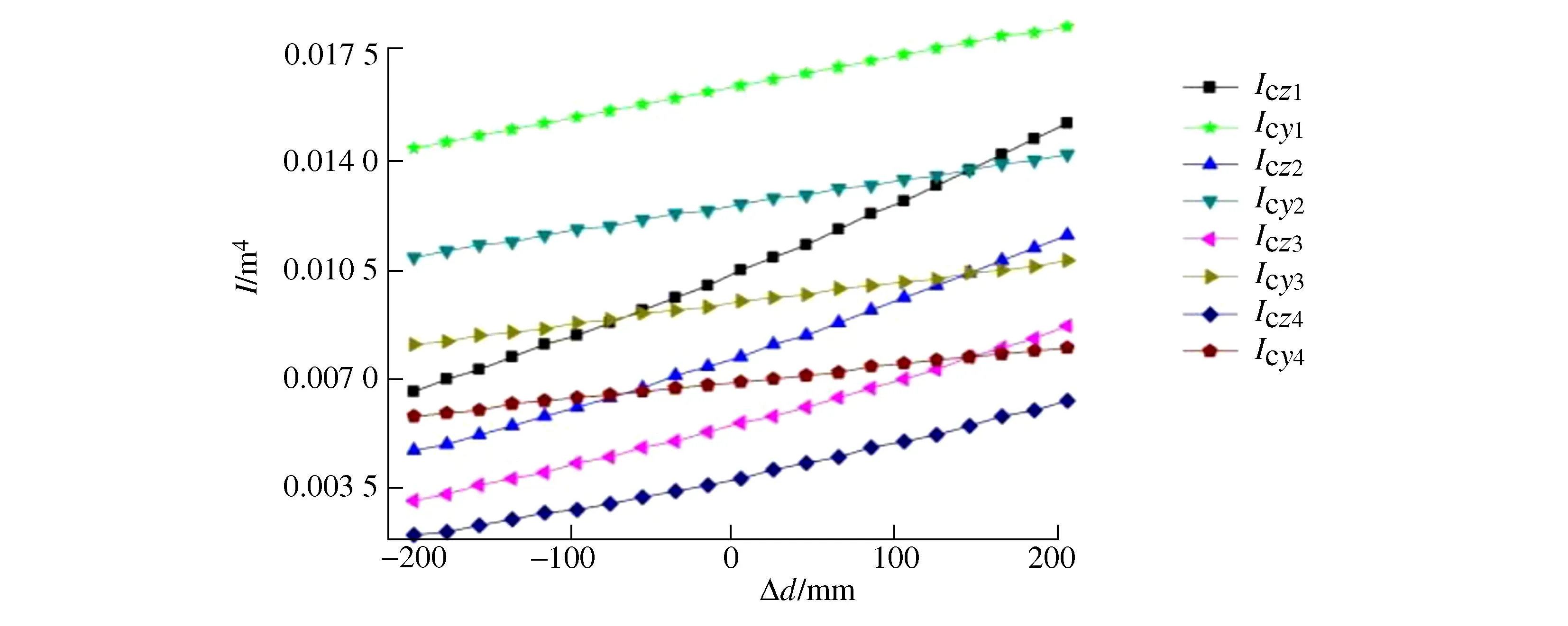
Figure 6 Variation of moment of inertia with increment d
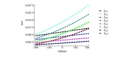
Figure 7 Variation of moment of inertia with increment H
From Figure 3 to Figure 7, it can be seen that the moment of inertia of the U-shaped section decreases with the increase of the inner radius R0of the arc transition, and increases with the increase of the height H of the whole section, the width d of the whole section, the thickness t of the upper cover plate and the thickness δ of the lower cover plate. This means that when the material, support mode and length of the telescopic boom of the U-shaped section are fixed, the critical load of the telescopic boom will decrease with the increase of the inner radius R0of the arc transition, and increase with the increase of the height H of the whole section, the width d of the whole section, the thickness t of the upper cover plate and the thickness δ of the lower cover plate.
4 Influence of section size on buckling
In this paper, it is taken as an example that the telescopic boom of a 300 t all-terrain crane produced by a crane factory. The full extension length of the telescopic boom is 61 m, the luffing angle is 76°, the amplitude is 14 m, and the rated lifting weight is 2.72×10⁴kg. The steel used in the telescopic boom is WELDOX1100, its elastic modulus is 206 GPa, Poisson′s ratio is 0.3, its yield strength is 1 100 MPa, and its tensile strength is 1 250 MPa. Firstly, the finite element software ANSYS15.0 is used to calculate the linear buckling of the telescopic boom, and then the ′Design Exploration′ module in the Workbench collaborative platform is used to analyze the linear buckling sensitivity[21]. In the buckling sensitivity analysis, all cross-sectional dimensions of the basic boom (including the height H0of the overall section, the width d0of the overall section, the inner radius r0of the arc transition, the thickness w01of the upper cover plate, the thickness w02of the lower cover plate) and the thickness of the upper and lower cover plates of the remaining sections (including w11, w12, w21, w22, w31, w32, w41, w42, w51, w52) are selected as design variables, and the buckling load factor (Load multiplier) is used as the output variable. The calculation of linear buckling critical load in ANSYS is equal to the initial load multiplied by the buckling load factor. When the initial load is constant, the buckling load factor directly characterizes the ability of the bar to resist buckling. The buckling sensitivity analysis process is shown in Figure 8. Firstly, static structural analysis (Static structural A) is carried out, then linear buckling analysis (Linear bucking B) is carried out, and finally response surface analysis (Response surface C) in ′Design Exploration′ is carried out.
4.1 Finite element model
The ′Design Modeler′ module in Workbench provides a good modeling function. In this paper, the finite element model of the telescopic boom is established by using ′Design Modeler′ and conceptual modeling. Firstly, six lines of equal length to each telescopic boom are drawn in the sketch plane. Then, ′Lines From Sketches′ is used to form a line body, and then a section is attached to each line body. Finally, all lines are selected to form new part. The finite element model of the telescopic boom is completed as shown in Figure 9 (because this paper analyzes the overall buckling of the telescopic boom rather than the local buckling, the lapping slider is temporarily not considered).
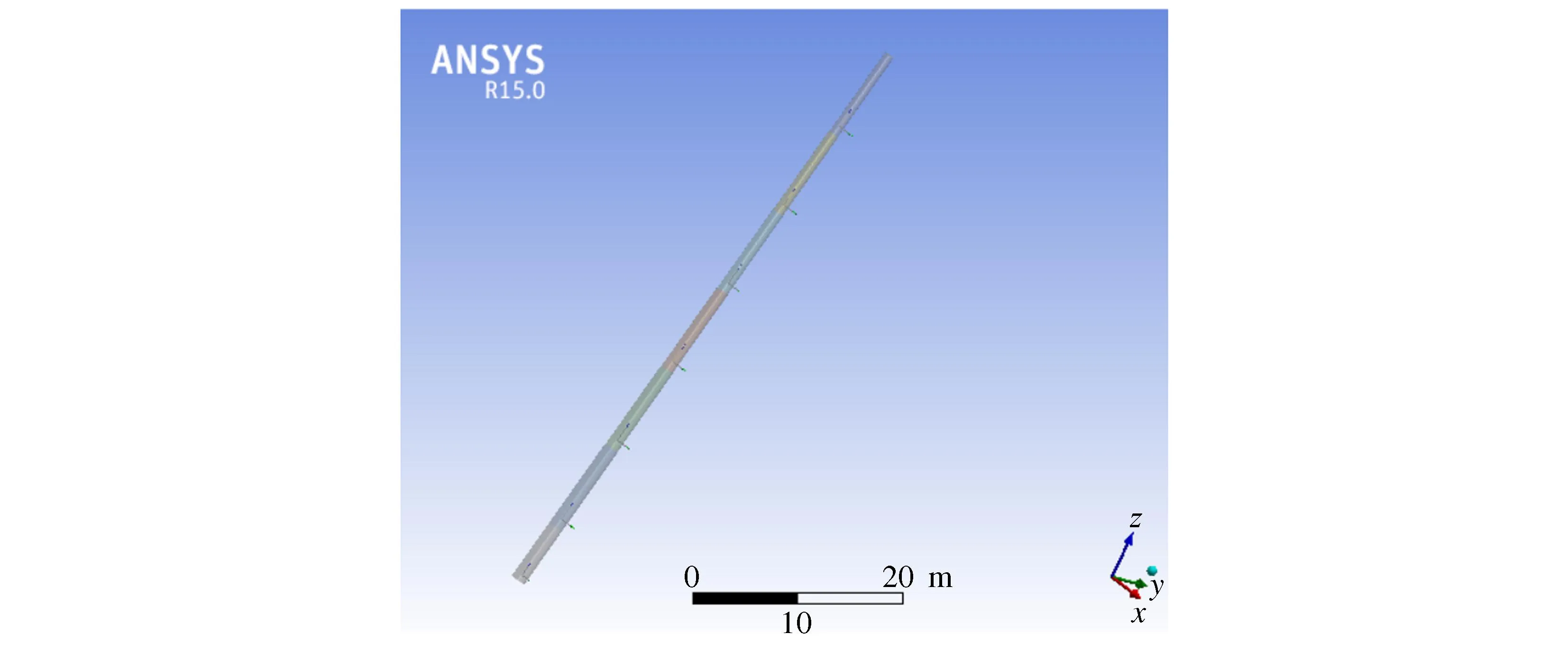
Figure 9 Finite element model of telescopic boom
4.2 Constraints and loads
In order to simulate the actual situation, ′Simply supported′ and ′Fixed rotation′ are set for the hinge point between the basic boom and the turntable, the hinge point between the luffing cylinder and the basic boom.The translational degrees of freedom along the x, y and z axes and the rotational degrees of freedom around the y and z axes are constrained, but the rotational degrees of freedom around the x axis are released. The telescopic boom is subjected to many forces, and its weight is achieved by adding gravity acceleration (g=9.8 m/s2). The wire rope tension FSis equal to 55 151 N, the lifting load PQis equal to 5.293 5×10⁵N, and the lateral horizontal force FCof the boom head is 38 118 N (the lateral horizontal force includes the horizontal force Ftgenerated by the swing of the item and the wind load 0.4 PW, in which the item swing angle α is 6°).
4.3 Meshing
The Workbench system provides a default mesh generation method that adapts to the current model. When the line body is meshed by default, its unit is BEAM188. In order to refine the mesh, the ′Relevance′ value in ′Details of mesh′ can be set higher. In this article, it is set to 100, and the ′Relevance center fine′ is set to fine. After meshing, the number of elements is 103 and the number of nodes is 207.
4.4 Solution and output parameter
After the current processing work is completed, click ′Solution (A6)′ under ′Static structural (A5)′ and ′Solution (B6)′ under ′Linear bucking (B5)′ in turn, and then click ′Total deformation′ to view ′Load multiplier′. The obtained ′Load multiplier′ is 1.536 7, which is set to the output parameter.
4.5 Creation of response surface
The response surface optimization analysis can be established by double-clicking the ′Response surface′ in ′Design modeler′. Its advantage is that it can dynamically display the relationship between input parameters and output parameters and sensitivity through charts. Double-click the ′Design of experiments′ to generate and calculate the experimental design points. The upper and lower bounds can be set by clicking each input parameter. The system defaults (1 ± 10%) of the initial value of the input parameter as the upper and lower limits. Click ′Preview′ to generate random test points. In this paper, the input parameter range adopts the default value of the system, and finally 288 experimental design points are generated. After the design point is generated, click ′Update′ to calculate the output parameter values corresponding to the input parameters of the design point. Double-click the ′Response surface′ item in the ′Response surface (C)′, click ′Update′ to update, and then you can see an image that reflects the relationship between the input parameters and the output parameters after fitting based on the experimental design point data, as shown in Figure 10.
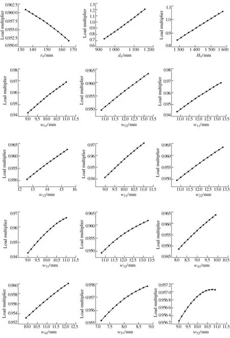
Figure 10 Relationship between input parameters and output parameters
It can be seen from Figure 10 that except that the buckling ′Load multiplier′ decreases with the increase of the inner radius (r0) of the arc transition of the basic arm section, ′Load multiplier′ increases with the increase of other input parameters (including d0, H0, w01, w02, w11, w12, w21, w22, w31, w32, w41, w42, w51, w52), which is completely consistent with the previous theoretical analysis.
It can be obtained that the sensitivity of each input parameter to the output parameter by clicking ′Local sensitivity′ and ′Local sensitivity curves′, as shown in Figure 11 and Figure 12.
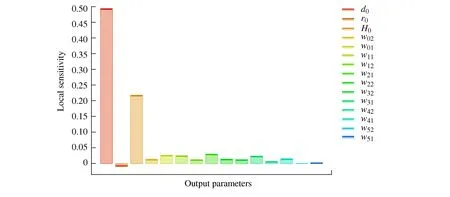
Figure 11 Local sensitivity for P7-Total deformation load multiplier
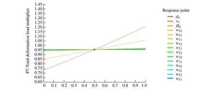
Figure 12 Local sensitivity curves for P7-Total deformation load multiplier
It can be seen from Figure 11 and Figure 12 that among the many input parameters, the most sensitive to the buckling load factor is the overall cross-section width d0of the basic boom, followed by the inner radius r0of the arc transition of the basic boom, and the least sensitive to the load factor is the thickness w52of the lower cover plate of the last section boom.
5 Conclusions
1) In this paper, the influence of U-shaped section size on the buckling critical force of the telescopic boom is analyzed by using the section inertia moment theory and the finite element method. It is found that when the material, support mode and length of the telescopic boom are constant, the buckling critical force of the telescopic boom decreases with the increase of the inner radius R0of the arc transition, and increases with the increase of the other section sizes (including the height H of the whole section, the width d of the whole section, the thickness t of the upper cover plate and the thickness δ of the lower cover plate). The same method can be used to analyze the cross sections of other shapes.
2) Through the ′Local sensitivity′ and the ′Local sensitivity curves′, it can be found that the sensitivity of the basic boom section size to the buckling critical force of the telescopic boom from large to small is the width d0of the overall section, the inner radius r0of the arc transition, the thickness w02of the lower cover plate, and the thickness w01of the upper cover plate. The minimum sensitivity of all parameters is the thickness w52of the lower cover plate of the end boom.
3) When the telescopic boom adopts a U-shaped section, a reasonable aspect ratio is beneficial to improve the overall stability. The arc transition part of the upper cover plate and the web should not be too large on the premise that the stress concentration can be solved.
The research and analysis results of this paper can provide some design reference for designers, so as to adopt reasonable section size and improve the buckling resistance of the telescopic boom.
 International Journal of Plant Engineering and Management2023年4期
- International Journal of Plant Engineering and Management的其它文章
- A Single Feasibility Study of System Multi-feature Analysis and Evaluation Tool Based on AADL Model
- The Topology Optimization Under the Static Loads
- Study on Development of Light Aluminum Step by Using Finite Element Analysis