
Calculation of Plane to Plane Orientation Error by Least Square Method Based on Coordinate Transformation
2013-06-02 06:17WANGXuHUANGMeifaCHENLeileiYANGZheng
机床与液压 2013年18期
WANG Xu ,HUANG Meifa,CHEN Leilei,YANG Zheng
School of Mechanical& Electrical Engineering,Guilin University of Electronic Technology,Guilin 541004,China
1.Introduction
The orientation error is one of the important specifications in the geometry measurement of the precision parts and has a significant influence on the quality and performance of product.In practical geometry measurement,it is very important to accurately and quickly obtain the evaluated results.
Currently,there are two methods to evaluate the orientation error,they are the traditional measurement method and least square method.The traditional measurement method has low measurement precision and is not capable to obtain the accurate error.Least Square Method is simple and quick but this method is only for the approximate evaluation and can not be applied for minimum zone evaluation.In a word,the existing measurement methods do not meet the requirement of the modern advanced manufacture industry[1-2].
The transformation of coordinate system is a process in which the rotation and translation of the coordinate system are used to obtain the evaluated values.This paper presents a least square method based on the transformation of coordinate system to evaluate orientation error.
2.Establishment of the optimum associated datum plane
The general process of this method includes two steps.First,we apply Least Square Method(LSM)to associate the initial datum plane.Second,we make the flatness error of the initial associated datum plane as far as possible to approach the minimum zone by using the corresponding transformation[3].
Assume that the measured point of arbitrary spatial orientation in the actual plane arepi(xi,yi,zi)(i=1,2,…,n).The equation of the initial associated datum plane M0could be expressed in Equation(1):

The distancedifrom pointpi(xi,yi,zi)(i=1,2,…,n)to planeM0could be expressed as Equation(2):
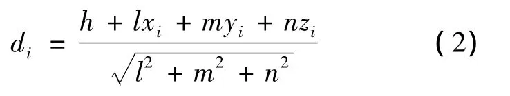
Where,diis the function ofl,m,n.The normal vector of planeM0is(l,m,n).According to the definition of least squares associated plane,the sum of squares of distance from pointpi(xi,yi,zi)(i=1,2,…,n)to planeM0is the minimum,we take the sum of squares function as the optimal target function:

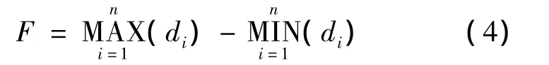
The values ofl,mandncould be obtained by the equation of the least square plane.The flatness error F is the difference between the maximum distance and minimum distance from the measured points to the ideal datum plane:
We take distance between measured points and plane as positive if these points are above the least squares associated plane,and the distance as negative if these points are below the least squares associated plane.

Fig.1 Relationship diagram of point Pi、 plane M0and M1
As shown in Fig.1(a),the initial associated datum planeM0is projected respectively in the directions which are perpendicular to the direction of tolerance zone and the direction of ligature of the highest contact point and the lowest contact point of tolerance zone(as shown in Fig.1(b)),the equation of the initial associated datum planeM0is already obtained.The normal vectorTof planeM0is(a0,b0,c0)and the flatness error of the planeM0isF.Through calculation and analysis,we rotate planeM0(rotate the normal vector of planeM0)consciously and slightly to decrease the value ofF.The optimum associated datum planeM1is acquired when the planeM0is slightly rotated.
The corresponding point of pointpiisPi.The distance from pointPi(xi,yi,zi)(i=1,2,…,n)to planeM0isFk.The maximum and minimum value ofFkisFiandFj,respectively.Fk=Fi-Fj=PiB0-PiA0.The pointB1can be obtained from the distance of ε (ε is a very small value)based on the pointA0alongA0Pi,and the pointA1can be obtained from the distance of ε based on the pointB0alongB0Pi.Both pointA1and pointB1belong to the optimum associated datum PlaneM1.The distance between pointPiand planeM1isFk'.The maximum and minimum value ofFk'isF'iandF'j,respectively.Fk'=F'i-F'j=PiA1-PiB1.Fk'<Fk.When planeM0is slightly rotated to acquire planeM1,the value of errorFcould be decreased[3].
3.Establishment of orientation error evaluation model
When tolerance t of given parallelism,perpendicularity or angularity is 0,the ideal angle is 0°,90°or a given certain angle,respectively.When the actual angle is deviated from the ideal angle,the parallelism,perpendicularity or angularity appears,respectively.Size of the deviation is the error of each projected tolerance[4].
As shown in Fig.2,the model of plane to plane orientation error evaluation is established uniformly by changing the ideal right angleQ.The tolerance zone direction of plane to plane orientation tolerance is unique.After the position of the datum feature is determined,two parallel planes(tolerance zone)of tolerating measured plane is also determined[4].
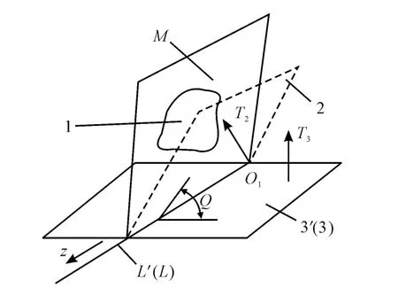
Fig.2 Plane to plane orientation error evaluation model
Associated plane of actual measured plane 1 is planeM.The equation of the associated planeMcould be expressed as Equation(5).

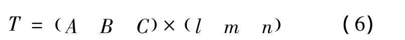
According to the optimum associated datum plane method,we evaluate the normal vectorTmof planeMwhich is(A,B,C).The normal vectorT3of datum plane 3 is(l,m,n).The intersection line of planeMand datum plane 3 is lineL,the direction vectorTof lineLcould be expressed as Equation(6).
本次设计预制混凝土板横向每7.0m设1条伸缩缝,底板纵向沿中心线设1条伸缩缝。伸缩缝形式均为矩型缝,宽均为2cm,错缝布置,缝宽2cm。缝内填2cm厚的绿豆砂,上部再灌厚4cm焦油膏。
Datum plane 3 is revolved by ideal correct angleQaround lineLto obtain auxiliary plane 2.
As shown in Fig.3,coordinate system rotation matrix could be derived.LineLwill be rotated to the position in which it is parallel to theZaxis.
Assume the direction vectorTof lineLbeT=(abc).The coordinate of pointO1in lineLis(xi,yi,zi).The coordinate of pointO1'is acquired by calculation model of coordinate rotation.The coordinate of pointO1'is(x'i,y'i,z'i).The calculation model of coordinate rotation could be expressed as E-quation(7)[5]:
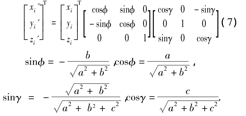

Fig.3 Coordinate system rotating figure
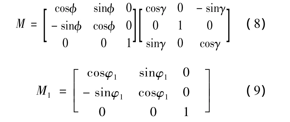
The coordinate rotation matrix is expressed as Equation(8)and(9).
As shown in Fig.2,the lineLis rotated to the position in which it is parallel toZaxis.LineL'is acquired by calculation model of coordinate rotation.The direction vector of lineL'isT'=TM.The normal vector of datum plane 3 isT3',T3'=T3M.Datum plane 3 is revolved by ideal correct angleQaround lineL'to obtain auxiliary plane 2.The normal vectorT2'of auxiliary plane 2 could be expressed as Equation(10).
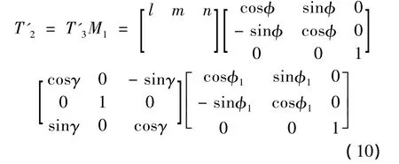
Where,φ1is equal toQ.The error value of the actual measured plane 1 to datum plane 3 is transformed into the distancedibetween each measured pointpi(xi,yi,zi)(i=1,2,…,n)and auxiliary plane 2.The difference of maximum distance and minimum distance is the error.
4.Verification of an example
Parallelism error evaluation of a box is taken as an example to verify the application of the method as shown in Fig.4.We use Coordinate Measuring Machine(CMM)to acquire discrete point coordinates of the datum plane and the measured plane.The parallelism data of the measured parts is shown in Tab.1.
In order to evaluate the orientation error,the superiority of the different algorithm is mainly embodied in the optimization of datum feature.The values of orientation error obtained by different evaluation methods are not comparable.
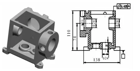
Fig.4 A box structure
Firstly,we apply traditional measurement method to evaluate plane to plane parallelism error by using dial indicator.According to the measuring method,the datum plane error is 0.403 mm,and the parallelism error is 0.037 mm[6].
Secondly,we utilize CMM(Hexagon,the model is global 07·10·07)to evaluate plane to plane parallelism error.The datum plane error is 0.236 mm,and the plane to plane parallelism error is 0.017 mm[7].
Finally,according to the mathematical model which is proposed in this paper,we can calculate the parallelism error by using the above method.The datum plane error is 0.221 mm,and the plane to plane parallelism error is 0.016 mm.The results of these three evaluation methods are compared in Tab.2.The comparison results show that the results obtained by the method in this paper are better than those of CMM and traditional measurement method,and the proposed method in this paper has strongest potential application value.
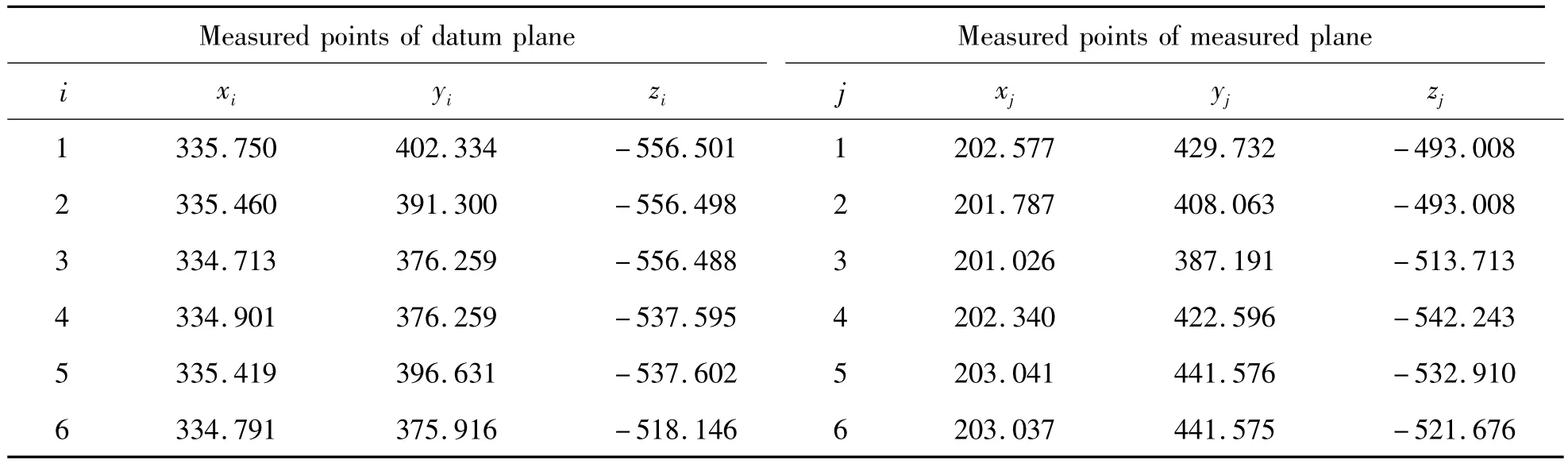
Tab.1 Parallelism data of the measured parts mm
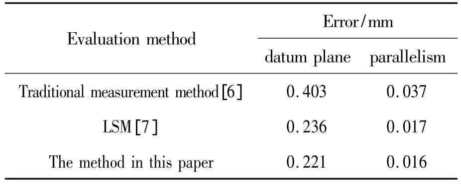
Tab.2 Calculation results comparison
5.Conclusions
In this paper,we adopt least square method to evaluate the plane to plane orientation error based on coordinate transformation.Through the comparisons of results,it shows that the present model is easy to program,and is capable to solve the error of parallelism,perpendicularity and angularity.Therefore,this method could be widely used in the real applications.
[1]LI Zhu,XU Zhengao,JIANG Xiangqian.Geometrical product specifications and verification[M].Beijing:Higher Education Press,2004.
[2]JIANG Xiangqian.Theory and Applications of New Generation Geometrical Product Specifications in Chinese[M].Beijing:Higher Education Press,2007.
[3]lIN Xiang.Research and Development of the Evaluation Flow for High-precision Space Parallel Error[J].Journal of Guiyang College,2011,23(11):112.
[4]WANG Xili.Application of Position Tolerance[M].Beijing:Administration of Machinery Industry,1981.
[5]CHEN Leilei.Calculate Form Error of Rotation Surface by Least Square Based on Coordinate Transformation[J].Chinese Journal of Construction Machinery,2011,28(3):58.
[6]BAO Jiading.Study on Orientation Tolerance Modeling and Evaluation Method Based on New GPS[D].Guilin:College of Mechanical& Electrical Engineering,2010.
[7]YANG Jinxia.Ftware Develop of Position Error Evaluation Based on Coordinate Measuring Datas[D].Xi’an:Technical University,2008.
猜你喜欢
天津科技(2022年4期)2022-04-20
实用中西医结合临床(2022年2期)2022-04-02
保健与生活(2021年12期)2021-06-10
环球中医药(2021年1期)2021-01-21
橡胶工业(2018年10期)2018-07-23
声学技术(2018年3期)2018-07-20
中成药(2018年5期)2018-06-06
——目镜套筒
上海计量测试(2016年1期)2016-08-03
中外医疗(2015年5期)2016-01-04
浙江理工大学学报(自然科学版)(2015年5期)2015-03-01

- 机床与液压的其它文章
- Strength Analysis and Optimization of a Torsion Beam Rear Suspension
- Development of Vibration Signal Acquisition and Analysis System for Machine Tools Based on LabVIEW
- Numerical Analysis and Experimental Research on Micro Milling Process with Cycloidal Tool Path
- Analysis of the Optimization of Gear Pump Pulsation Based on Matlab
- Simulation Evaluation and Performance Analysis of a Double Coil Magnetorheological Valve
- Remote Condition-based Maintenance Approach to Hydraulic System of Construction Machinery