
Effect of tool pin profile on microstructure and tensile properties of friction stir welded dissimilar AA 6061-AA 5086 aluminium alloy joints
2015-11-01 07:13ILANGOVANRAJENDRABOOPATHYVBALASUBRAMANIAN
Defence Technology 2015年2期
M.ILANGOVAN*,S.RAJENDRA BOOPATHYV.BALASUBRAMANIAN
aDepartment of Mechanical Engineering,College of Engineering Guindy,Anna University,Chennai 600025,India
bCenter for Materials Joining&Research(CEMAJOR),Department of Manufacturing Engineering,Annamalai University,Annamalai Nagar 608002,India
Effect of tool pin profile on microstructure and tensile properties of friction stir welded dissimilar AA 6061-AA 5086 aluminium alloy joints
M.ILANGOVANa,*,S.RAJENDRA BOOPATHYa,V.BALASUBRAMANIANb
aDepartment of Mechanical Engineering,College of Engineering Guindy,Anna University,Chennai 600025,India
bCenter for Materials Joining&Research(CEMAJOR),Department of Manufacturing Engineering,Annamalai University,Annamalai Nagar 608002,India
Joints between two different grades of aluminium alloys are need of the hour in many light weight military structures.In this investigation,an attempt has been made to join the heat treatable(AA 6061)and non-heat treatable(AA 5086)aluminium alloys by friction stir welding(FSW)process using three different tool pin profiles like straight cylindrical,taper cylindrical and threaded cylindrical.The microstructures of various regions were observed and analyzed by means of optical and scanning electron microscope.The tensile properties and microhardness were evaluated for the welded joint.From this investigation it is founded that the use of threaded pin profile of tool contributes to better flow of materials between two alloys and the generation of defect free stir zone.It also resulted in higher hardness values of 83 HV in the stir zone and higher tensile strength of 169 MPa compared to other two profiles.The increase in hardness is attributed to the formation of fine grains and intermetallics in the stir zone,and in addition,the reduced size of weaker regions,such as TMAZ and HAZ regions,results in higher tensile properties.
Friction stir welding;Dissimilar joint;Aluminium alloy;Tool pin profile;Microstructure;Tensile strength
1.Introduction
AA 5086 is a strain hardenable aluminium alloy and AA 6061 is an age hardenable aluminium alloy,but both alloys exhibit higher strength to weight ratio,good ductility,and good corrosion resistance[1-3].The dissimilar joining of these two materials leads to the combined properties of both materials,which makes this combination very much required in military applications such as light combat aircraft(LCA),light combat vehicle(LCV),future main battle tank(FMBT),bridge layer tank(BLT),armoured ambulance,submarine torpedo,etc.Aluminium materials can generally welded usingfusion welded process like gas tungsten arc welding(GTAW)and gas metal arc welding process(GMAW).However,fusion welding of dissimilar materials is a greater challenge due to the differences in chemical composition,melting point,coefficient of thermal expansion and other mechanical properties[4].In addition,the problems related to solidification such as porosity,hot cracking,etc.,deteriorate the quality of weld joint.The formation of coarse grains and large intermetallic compounds in the weld region results in poor mechanical properties.The formation of thick tenacious ceramic oxide layer on the surface restricts the welding arc to weld the aluminium alloys.This oxide layer restricts many fusion welding processes to weld the aluminium alloys.
Friction stir welding(FSW)is a solid state welding process invented to weld the aluminium alloys[5,6].FSW allows the materials to be welded well below the melting temperature of the materials.Thus the formation of brittle solidified products can be reduced and the grain boundary cracking due toliquation can be eliminated.Many metallurgical reactions between the dissimilar materials at the elevated temperature can be avoided.Thus FSW is a prospective welding process which can also join the dissimilar materials having incompatibilities[7].The formation of defect free friction stir processed or weld region is mainly based upon the material flow behaviours.The dynamic recrystallization in the dissimilar weld region is characterized by the mixing or complex intercalation of the dynamically recrystallized fine grains[8].
http://dx.doi.org/10.1016/j.dt.2015.01.004
2214-9147/Copyright©2015,China Ordnance Society.Production and hosting by Elsevier B.V.All rights reserved.

Table 1 Chemical composition(wt%)of aluminium alloys used in this investigation.
In FSW,the heat generation is due to the rubbing of tool on work piece and the plastic deformation of the material.Tool pin profile has a remarkable effect on the rubbing and the foremost effect on the plastic deformation.The ratio of swept volume to pin volume decides the material flow[9].The material has to swirl according to tool rotational speed and has to move with respect to tool travel speed in order to get defect free weld zone.Thomas et al.developed many pin profiles like Whorl,MX Triflute,A-skew,etc.,for the special purpose[10]. Each pin profile has its own material flow characteristic like good orbital forging,higher mixing of materials,reduction of TMAZ,HAZ regions,etc.Lot of research works[11-15]had been carried out throughout the world to understand the effect of tool pin profile on microstructure and mechanical properties.Most of the literatures are focused on similar joints like Al alloy to Al alloy,Mg alloy to Mg alloy.Few investigations have been carried out on dissimilar joints.Very few investigations have been carried out on microstructural characterization and mechanical properties of friction stir welded heat treatable(AA 6061)alloy and non-heat treatable(AA 5086)alloy.However,the published information on the effect of tool pin profile on the above-mentioned combination of dissimilar aluminium alloy joints is very scanty.
2.Experimental procedure
Rolled plates of AA 5086-O and AA 6061-T6 aluminium alloys were used in the present investigation.AA 5086-O Al alloy was placed in the retreating side and AA 6061-T6 Al plate was placed in the advancing side because AA 6061 has higher flow strength than AA 5086 aluminium alloy.Due to high frictional force and high material excavation force created in the advancing side,the hard AA 6061 aluminium alloy was placed in the advancing side.150 mm×150 mm×6 mmjoint configuration was used for the fabrication of FSW joints. Chemical compositions and mechanical properties of the parent materials were evaluated and presented in Tables 1 and 2,respectively.Many trial experiments were conducted by varying tool rotational speed(600-1200 rpm)and welding speed(10-40 mm/min)from the trail experiments.It was found that the surface defect free joints were fabricated at the tool rotational speed of 1100 rpm and the welding speed of 22 mm/min,irrespective of tool pin profile.Hence these parameters were kept constant for making the dissimilar joints using different pin profiles.The welding conditions and process parameters used to fabricate the joints are given in Table 3.Three pin profiles,namely,straight cylindrical(STC),threaded cylindrical(THC)and tapered cylindrical(TAC),were used to fabricate the joints(Fig.1).The tensile samples were extracted along the transverse direction and prepared as per ASTM E8M guidelines(Fig.2(a)).Tensile test was carried out in 100 kN electro-mechanical controlled universal testing machine(Make:FIE,India;Model:UNITECH 94001).Three samples were prepared from each joint and the average value was taken for analysis.The 0.2%offset yield strength,ultimate tensile strength,percentage of elongation and joint efficiency were evaluated from un-notched tensile sample.Notch tensile strength and notch strength ratio were evaluated from notched tensile sample.The fractured surfaces of tensile test samples were analyzed using scanning electron microscope(SEM).A Vickers microhardness tester(SHIMADZU,Japan;model HMV-2T)was employed for measuring the hardness across the transverse section of the joint with load of 50 g and dwell time of 15 s.
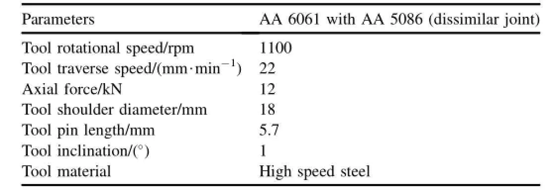
Table 3 Welding condition and process parameters.
Microstructural examination was carried out using an optical microscope(MEJI,Japan;model MIL-7100)incorporating image analyzing software(Metal Vision).The samples for metallographic examination were polished using various grades of emery sheets.Final polishing was done using alumina powder in the disc polishing machine.The samples were etched with standard Keller's reagent as per the ASTM standard E407.Scanning electron microscopy(SEM)was employed to analyze the microstructure and fracture surfacesof tensile samples at higher magnification.The features in the weld region were characterized using transmission electron microscope(TEM)(Make:PHILIPS,120;Model:CM20).

Table 2 Mechanical properties of aluminium alloys used in this investigation.
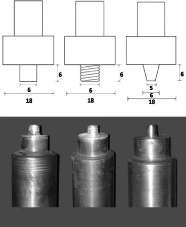
Fig.1.Photograph of tools with different pin profiles.
3.Results
3.1.Tensile properties
Three un-notched tensile samples were extracted from each joint.These samples were tested using universal testing machine(UTM)as per the ASTME 8-04 guidelines.The average of three readings is presented in Table 4.Since the population size is very small,the standard deviation was not calculated. However all three readings are within±5%variation.The results show that the tensile properties of the welded joints are significantly varied with regard to different pin profiles.A higher tensile strength of 169 MPa was attained in the joint made by THC pin profiled tool.A lower tensile strength of 126 MPa was attained in the joint made by STC pin profiled tool,which is 51.54%lower than that of unwelded AA 6061 alloy and 40.57%lower than that of unwelded AA 5086 alloy. TAC pin profile results in the tensile strength of 163 MPa which is 35%and 20.29%lower than those of the parent material AA 6061 and AA 5086,respectively.The percentage of elongation of welded joints was lower than that of the parent materials.The three different pin profiles show relatively the same percentage of elongation.The effect of notch on the tensile behaviour of weld joints was evaluated.It was found that the tensile strength is higher than the smooth tensile strength.Higher notch tensile strength of 178 MPa was observed in the joint fabricated by threaded cylindrical profiled pin tool,and lower notch tensile strength of 130 MPa was observed in the joint fabricated by straight cylindrical pin tool. The notch strength ratio is greater than 1 which represents that the failure mode is notch ductile.Fig.2(a)shows the dimensions of tensile specimens.Fig.2(b)shows the photograph of the tensile test specimen before test and Fig.2(c)shows thefailure location of the tensile tested samples.The fractures were observed in the stir zone for the straight cylindrical pin profile and the advancing side-TMAZ region for threaded cylindrical and plain taper cylindrical pin profiles.

Fig.2.Dimensions of tensile specimen and photograph of the tensile test specimen.
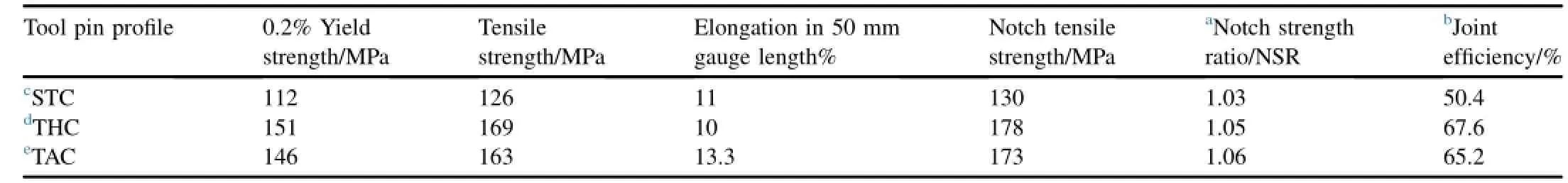
Table 4 Transverse tensile properties of FSW joints.
3.2.Macrostructure
Fig.3 shows the macrostructures for three different pin profiles.The top surface of the weld region shows defect free equally spaced material consolidated ripples.The clear interfaces of various regions like unaffected parent metal zone,heat affected zone,thermo-mechanical heat affected zone and stir zone were clearly visible.Onion ring formation was found in the pin influenced regions of all the pin profiles.The macrostructure of STC pin profile shows defect in the mid thickness region at the advancing side.A large amount of single mass extruded material of AA 5086 was observed in the mid thickness region.Equal amount of AA 6061 and AA 5086 was alternately stacked to form the onion rings in the pin influenced region.Macrostructure of THC pin profile shows lower amount of segregated mass of AA 5086 in the mid thickness region.As like macrostructure of STC pin profile,the formation of onion ring was not observed in the pin influenced region.In the mid thickness region,both STC and THC profiles exhibit a blunt complex flow of materials.Unlike two pin profiles above,the limited traces of AA 5086 were presented in the mid thickness region,and the sharp transformation of material flow was observed in the TAC pin profile.Relatively lower size of onion ring was observed in the pin influenced region of TAC pin profile.
3.3.Microstructure
The flow patterns,grain size and its orientation in various regions of STC pin profile were analyzed using optical microscope and shown in Fig.4.Fig.4(a)shows the shoulder influenced region near to the advancing side,in which the grains were finer and oriented towards pin influenced region. Fig.4(b)shows the microstructure of shoulder influenced region at the centre of the stir zone.Dynamically recrystallized equiaxed grains were observed.Fig.4(c)shows the microstructure of interface in the shoulder influenced region near to the retreating side.The grains were heavily deformed in the TMAZ region next to the stir region.Fig.4(d)shows the microstructure of mid thickness interface in the stir zone.With the increase of distance from stir zone to HAZ,the grain sizes were increased in the TMAZ region.Region e shows that the grains are orbitally bended in the nugget region.Fig.4(f)and(h)shows the lamellar flow of dissimilar materials in the pin influenced region.The thicknesses of two materials in the lamellar structure are almost equal.Fig.4(g)shows the microstructure of pin influenced region.The grain sizes are relatively smaller than those in the shoulder influenced region. Fig.5(a)shows the interface microstructure of the advancing side shoulder influenced region in which AA 5086 majorly contributes to this region.Fig.5(b)shows the centre of theshoulder influenced region in which both the dissimilar materials contribute to the region.Fig.5(d)and(f)shows the interface microstructures of advancing side mid thickness region and pin influenced region.The upward flow of TMAZ materials was observed from both the microstructures.Region e shows the mid thickness region in which the regular material patterns at the periphery of the onion rings were altered.The inherent nature of shoulder influenced region,downward flow of material,was not significant in the shoulder influenced region(Fig.6(a)-(c)).In the mid thickness region,the complex intercalation pattern was observed at the advancing side(Fig.6(d)).In the mid thickness region at the retreating side,the material flow is regular but complexly oriented.Fig.6(f)and(g)shows the interface microstructures,and Fig.6(g)shows the material flow of onion ring in the pin influenced region.The material is deformed upward towards the stir zone.
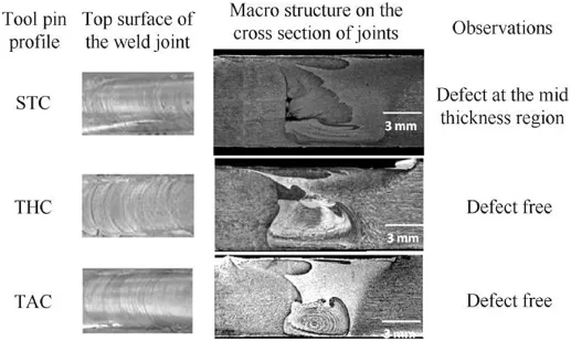
Fig.3.Macrograph.
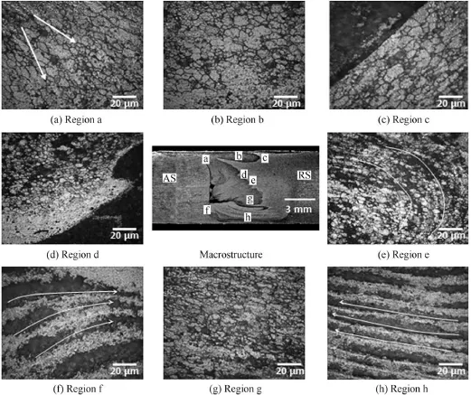
Fig.4.Microstructure of STC joint.
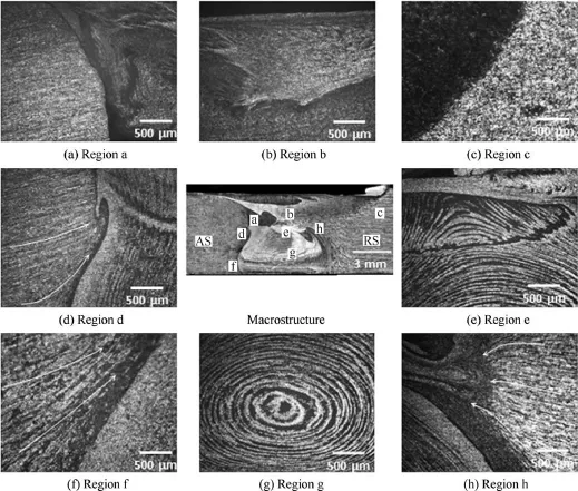
Fig.5.Microstructure of THC joints.
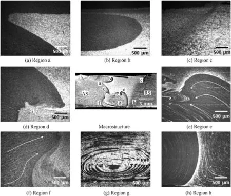
Fig.6.Microstructure of TAC joints.
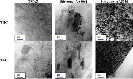
Fig.7.TEM image.
Fig.7 shows the TEM images of stir zone and TMAZ region of THC and TAC pin profiles.For THC pin profile,thestir zone of AA 6061 results in θ precipitates with 500 nm in diameter and 100 nm in thickness and the TMAZ region shows precipitate free zone along with few dislocations.Stir zone of AA 5086 shows dislocation cell structure throughout the matrix.For TAC pin profile,the stir zone of AA 6061 results in θ precipitates with 500 nm in diameter and 100 nm in thickness,and the TMAZ region results in a precipitate free zone along with coarse θ precipitates.The stir zone of AA 5086 shows a dense dislocation cell structure throughout the matrix.
3.4.Microhardness
Fig.8 shows the microhardness plot of both pin profiles at the central line along the transverse direction.The hardness variation of each region was plotted with respect to the macrostructure.The graph shows the decreasing trend of hardness from AA 6061 PM to HAZ.The Hardness is further decreased in AS-TMAZ region.The AS-TMAZ was identified as the softest region in the microhardness plot for both pin profiles.The microhardness values in the stir zone result in higher hardness values than those in HAZ and TMAZ regions. Nonetheless,the fluctuation of hardness values was observed in the stir zone.In the retreating side,no such variation in hardness was observed at the advancing side.The threaded cylindrical pin profile shows higher hardness than the plain taper cylindrical pin profile in the stir zone.
3.5.Fractographs

Fig.8.Microhardness.
Figs.9 and 10 show the fractographs of smooth and notched tensile test samples.The Straight cylindrical fine dimples with few featureless flat surfaces are shown in Fig.9(a).The threaded cylindrical pin profile shows the fine populated dimples oriented towards the loading direction(Fig.9(b)).The plain taper pin profile shows the fine populated dimples but is larger in size than the threaded pin profile(Fig.9(c)).Fig.10(a)and(b)shows the fractographs of notched tensile samples of straight and threaded cylindrical pin profiles.It shows large sized dimples along with flat featureless fracture surfaces.The plain taper cylindrical pin profile shows the fine dimples along with the cracks on the fracture surface.
4.Discussion
4.1.Effect of pin profile on tensile properties
The tensile strength of dissimilar welded joints mainly depends on the existence of the defect in the stir zone,mechanical interlocking of material,coarsening of grains in the non-heat-treatable alloy,size,shape,strain hardening in the stir zone and distribution of precipitates.The lower tensile strength of straight cylindrical pin profile is attributed to the presence of defect in the stir zone.During loading,the tunnel defects at the advancing side act as the failure initiation site. The higher tensile strength was observed for threaded pin profile.From Fig.10,it was identified that the fracture was located in TMAZ region at the advancing side.For the heat treatable aluminium alloy,the strengthening is mainly due to the presence of precipitates rather than the grain size[16,17]. AA 6061 was strengthened by the presence of Mg2Si precipitates.Generally during FSW,the temperature generated in the stir zone is high enough to solidify the region.For the threaded cylindrical pin,the precipitate is partially dissolved in the stir zone.In addition,few θ′precipitates is transformed to stable θ precipitates,and few coarser θ′precipitates are present in the stir zone.The precipitates are covered by the dislocations which hinder the dislocation motion during tensile loading[18].This is the reason why the AA 6061 material in the stir zone is strengthened.Since AA 5086 is a non-heattreatable Al alloy which is strengthened by the strain hardening in the stir zone.The severe plastic deformation due to intense stir of threaded pin profile results in higher strain energy relative to the taper pin profile,and AA 5086 also has dense dislocation in the stir zone[19].Due to dynamic recrystallization in the stir region,the fine recrystallized equiaxed grains are presented in the stir zone.The availability of the precipitates plays a vital role rather than magnitude of strain hardening and grain boundary.Since the thermal cycle prevails,the dissolution of precipitates was observed in the AS-TMAZ region.Thus the AS-TMAZ region is identified as the softer region among the various regions of FSW joint. During tensile loading the strain localization occurred in the AS-TMAZ region leading to the failure of AS-TMAZ region. The mixing of dissimilar materials is facilitated more easily by the threaded pin profile than the plain taper pin profile.Since meshing of dissimilar materials increases,the mechanical interlocking between the materials increases.During the tensile loading,the mechanical interlocking acts as self-balancing for limiting deformation of dissimilar materials[20].This isthe reason why the strength of threaded cylindrical pin profile is higher.The ductility's of the three pin profiles are lower than those of the base materials.The ductility of the weld region is greatly reduced up to 50%.The reduced ductility of the precipitation hardenable alloy joints was attributed to strain localization within the lower strength weld region.
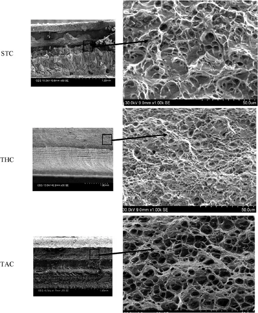
Fig.9.Fractographs of smooth(un-notched)tensile specimens.
4.2.Effect of pin profile on macro and microstructure
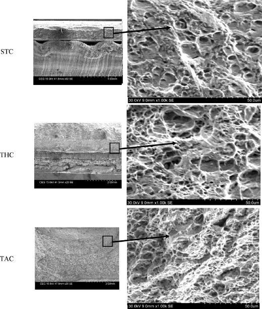
Fig.10.Fractographs of notched tensile specimens.
All three pin profiles yielded the surface defect free joints with tool rotational speed of 1100 rpm and welding speed of 22 mm/min.Under these welding conditions,the heat generation is almost the same for the three tool pin profile.It is well known that 2/3 of heat generation is caused by mechanical friction between tool shoulder and plate to be joined and 1/3 of heat generation is caused by pin profile by means of deformation included heat generation.Under this condition,the straight cylindrical pin yielded a defective joint,but the tapered and threaded cylindrical pins yielded the defect free joints.This may be due to improper flow of plasticized material around the tool pin during stirring.This suggests that the deformation included heat generation(by the pin)is marginally insufficient compared to other pin profiles.From this investigation,it is found that the straight cylindrical pin is not preferable to weld the dissimilar grades of aluminium alloys,especially AA 6061 with AA 5086.In friction stir welding,the joining of the materials at the weld interface is achieved by the frictional heat generated between the tool and the work piece and the material flow.Tool shoulder generates 80%of total heat generation of FSW and the pin influence up to 20%of heat generation.In addition,the pin profile has greater effect on the material flow behaviour.Many researchers concluded that the heat input decides the formation and location of defect in the stir zone[21,22].In spite of the same heat input range,the different pin profiles alter the material flow,defect formation and its location.From the aspect of heating,the process parameters,the ratio of shoulder diameter to pin diameter(D/d ratio),and the ratio of shoulder diameter to plate thickness(D/T ratio)are significant,but the stirring and flow direction of material are greatly influenced by the geometry of tool pin profile[23-26].The plasticized material below the shoulder must be adequately stirred and mixed with the material and makes it flow around the pin.The forward motion of the tool extrudes the stirred material from the front to the back of the pin.Straight cylindrical pin profile results in tunnel defects in the advancing side(Fig.3(a)).During FSW,the material is excavated from advancing side to retreating side at the front of the tool and at the rear of the tool,and flows from retreating side to advancing side to fill a vacancy created during excavation[27].This is the reason for the defect formation at the advancing side since the straight cylindrical pin does not directs the material in such a way to fill the vacancy created during excavation.The stir zone shows three distinct regions along the thickness direction,namely unmixed region(UMR),mechanically mixed region(MMR)and stirringinduced plastic flow region(SPFR)[28].Straight cylindrical pin profile does not result in SPFR region.This was attributed to that the intense stirring of dissimilar materials was not created by the straight cylindrical pin profile.The featureless plain surface of pin profile results in lesser grasp of material which promotes sliding of materials around the pin.The microstructure of threaded pin profile shows all the three regions,namely UMR,MMR,and SPFR(Fig.5).The defect free joining of dissimilar materials can be achieved using threaded pin profile.The surface area of threaded pin profile is larger than those of the other two pin profiles.Thus the interfacial area subject to contacting with the material is larger,which increases the frictional heat around the pin in turn.This creates local softening of materials and enables to improve the flow around the pin.During plunging of the pin the materials get extruded vertically.The shoulder prevents the materials from escaping.Further this material is transported orbitally downwards following the threads.Thus the helical flow path of threaded pin profile supports the vertical flow,rotational flow and translation motion of materials.This is the reason that the defect free stir zone is formed using threaded pin profile.The microstructure of plain taper pin profile(Fig.6)shows three distinct regions,namely UMR,MMR,andSPFR,as like as threaded pin profile.Since the material flow is driven mainly by the pin and no shoulder profile is available,the dissimilar materials cannot be mixed in the shoulder influenced region(UMR),but rather are extruded.Due to the axial force the material flows downwards and gets spread towards the mid thickness region.The pin volume of plain taper pin is smaller than that of the tool with plain and threaded cylindrical pins.The pin inclination provides a larger swept volume,which in turns allows the material to flow around the pin.The stir zone composed of an unmixed region in the shoulder influenced region,a rigid disc rotation flow zone as approached to the mid thickness region and a radially regular vortex onion ring flow zone(Fig.5(c)).The onion ring formed in the pin influenced region of threaded cylindrical and plain taper pin profiles can be characterized as extrusion of one layer of semi-cylinder in one rotation of the pin,and a crosssectional slice through such a set of semi-cylinder results in the onion ring like arrangement of materials[29,30].Since AA 6061 and AA 5086 have relatively same yield strength,the pin intensely deformed both the materials equally and orbitally stacked in the weld nugget region.In the mid thickness region,the complex intercalated meshing of dissimilar materials are observed for the plain taper pin profile.The pin influenced region has sole effect of the pin but in the mid thickness region the material flow due to shoulder gets altered by the pin effect. This creates a turbulent flow of materials in the transformation zone.The intercalated microstructure can be characterized as the swirls and vortexes of dynamically recrystallized(DRX)flow of dissimilar material.The intercalated zone(Fig.5(h))composedofdifferentlydeformedgrainsanddifferent elemental compositions.Thus it is appear to be distinct fluid patterns as like complex flow in gas and liquid turbulent mixing.Since the threads in the threaded pin profile regulate the material flow,the intercalated material flow is not observed for the threaded pin profile.
4.3.Effect of pin profile on microhardness
The complex intercalated microstructure and the orbitally stacking of dissimilar materials in the stir zone results in the fluctuation of hardness values in the stir zones of both pin profiles.The fluctuation of hardness values in the stir zone of dissimilar materials was also reported earlier[31].In the retreating side the hardness values get increased towards the stir zone from the TMAZ region(Fig.8).This was attributed to strain hardening of non-heat treatable AA 5086 aluminium alloy in the stir zone.In addition to the increased grain boundaries due to dynamic recrystallization the hardness values is higher in the stir zone.The hardness values get deeply decreased at the advancing side of TMAZ region.Since AA 6061 aluminium alloy is a heat treatable aluminium alloy,its mechanical properties are highly influenced by the thermal conditions.Since the heating and cooling cycles prevail during welding,the precipitates are dissolved in the AS-TMAZ region.Thus this softened region results in poor hardness values. Such the softening of weldment in neighbouring region did not occur during FSW for the non-heat treatable aluminium alloys. Thus not much hardness variations are observed at the retreating side.
5.Conclusions
The effects of tool pin profile on microstructure and tensile properties of friction stir welded dissimilar AA 6061-AA 5086 aluminium alloy joints were investigated and the following conclusions are derived.
1)Of the three tool pin profile used,the straight cylindrical pin profile tool yielded cross-sectional macro level defects in the stir zone and hence is not available for AA 6061 and AA 5086 dissimilar joints.
2)Threaded and tapered cylindrical pin profile tools yielded defect free joints(both surface and cross-sectional).The tensile properties of these joints are more or less similar(±5%variation).However,the threaded cylindrical pin profile tool is preferred over the tapered cylindrical pin profile tool due to the superior performance of the joints.
3)Formation of finer and uniformly distributed precipitates,circular onion rings and smaller grain are the reasons for superior performance of joints fabricated by threaded pin profiled tool compared to tapered pin profiled tool.
Acknowledgement
The authors gratefully acknowledge the support extended by the Centre for Materials Joining&Research(CEMAJOR),Department of Manufacturing Engineering,Annamalai University,Annamalai Nagar,India to carry out this research.
[1]Perez-Bergquist Sara J,Rusty Gray III GT,Ellen K Cerreta,Carl P Trujillo,Alex P´erez-Bergquist.The dynamic and quasi-static mechanical response of three aluminum armor alloys:5059,5083 and 7039.Mater Sci Eng A 2011;528:8733-41.
[2]Katsas S,Nikolaou J,Papadimitriou G.Microstructural changes accompanying repair welding in 5xxx aluminium alloys and their effect on the mechanical properties.Mater Des 2006;27:968-75.
[3]Kumbhar NT,Bhanumurthy K.Friction stir welding of Al 6061 alloy. Asian J Exp Sci 2008;22(2):63-4.
[4]Luijendijk T.Welding of dissimilar aluminium alloys.J Mater Process Technol 2000;103:29-35.
[5]Thomas WM,Nicholas ED,Smith SD,Das SK,Kaufman JG,Lienert TJ. In:Aluminum 2001-proceedings of the TMS 2001 aluminum autom and join ses.TMS;2001.p.213.
[6]Thomas WM,Johnson KI,Wiesner CS.Friction stir welding-recent developments in tool and process technologies.Adv Eng Mater 2003;5:485-90.
[7]Li Y,Murr LE,McClure JC.Flow visualization residual microstructures associated with the friction-stir welding of 2024 aluminum to 6061 aluminum.Mater Sci Eng A 1999;271:213-23.
[8]Somasekharan Anand C,Murr Lawrence E.Fundamental studies of the friction-stir welding of magnesium alloys to 6061-T6 aluminum.In: Proceedings of the TMS.Magnes Tech;2004.p.31-6.
[9]Thomas WM,Dolby RE,David SA,DebRoy T,Lippold JC,Smartt HB. In:Proceedings of the sixth international conference on trends in welding research.Pine Mountain,GA:ASM International;2003.p.203-11.
[10]Thomas WM,Braithwaite ABM,John R.In:Proceedings of the third internationalsymposiumonfrictionstirwelding,Kobe,Japan;September 2001.p.27-8.
[11]Elangovan K,Balasubramanian V,Valliappan V.Effect of tool pin profile and tool rotational speed on mechanical properties of friction stirweldedAA6061aluminiumalloy.MaterManufProc 2008;23:251-60.
[12]Lammlein DH,DeLapp DR,Fleming PA,Strauss AM,Cook GE.The application of shoulderless conical tools in friction stir welding:an experimental and theoretical study.Mater Des 2009;30:4012-22.
[13]Elangovan K,Balasubramanian V.Influences of pin profile and rotational speed of the tool on the formation of friction stir processing zone in AA2219 aluminium alloy.Mater Sci Eng A 2007;459:7-8.
[14]Chowdhurya SM,Chena DL,Bholea SD,Caob X.Effect of pin tool thread orientation on fatigue strength of friction stir welded AZ31B-H24 Mg butt joints.Proc Eng 2010;2:825-33.
[15]Kumar K,Satish Kailas V.The role of friction stir welding tool on material flow and weld formation.Mater Sci Eng A 2008;485:367-74.
[16]Mahoney MW,Rhodes CG,Flintoff JG,Spurling RA,Bingel WH. Properties of friction-stir-welded 7075 T651.Metall Mater Trans A 1998;29A(7):1955-64.
[17]Rhodes CG,Mahoney MW,Bingel WH,Spurling RA,Bampton CC. Effects of friction stir welding on microstructure of 7075 aluminum.Scr Mater 1997;36:69-75.
[18]Swearengen JC.The thermo mechanical behavior of 6061 aluminum magnesium-silicon alloy.Mater Sci Eng 1972;10:103-7.
[19]Yutaka Sato S,Seung Hwan Park C,Hiroyuki Kokawa.Microstructural factors governing hardness in friction-stir welds of solid-solutionhardened Al alloys.Metall Mater Trans A 2001;32(12):3033-42.
[20]Venkateswaran P,Reynolds AP.Factors affecting the properties of friction stir welds between aluminum and magnesium alloys.Mater Sci Eng A 2012;545:26-7.
[21]Rajakumar S,Muralidharan C,Balasubramanian V.Predicting tensile strength,hardness and corrosion rate of friction stir welded AA6061-T6 aluminium alloy joints.Mater Des 2011;32:2878-80.
[22]Rajakumar S,Balasubramanian V.Correlation between weld nugget grain size,weld nugget hardness and tensile strength of friction stir weldedcommercialgradealuminiumalloyjoints.MaterDes 2012;34:242-51.
[23]Esmaeili A,Zareie Rajani HR,Sharbati M,Besharati Givi MK,Shamanian M.The role of rotation speed on intermetallic compounds formation and mechanical behavior of friction stir welded brass/ aluminum 1050 couple.Intermetallics 2011;19:1711-9.
[24]Jayaraman M,Sivasubramanian R,Balasubramanian V.Effect of process parameters on tensile strength of friction stir welded cast LM6 aluminium alloy joints.J Mater Sci Technol 2009;25(5):655-7.
[25]Malarvizhi S,Balasubramanian V.Influences of tool shoulder diameter to plate thickness ratio(D/T)on stir zone formation and tensile properties of friction stir welded dissimilar joints of AA6061 aluminum-AZ31B magnesium alloys.Mater Des 2012;40:453-60.
[26]Oertelt G,Babu SS,David SA,Kenik EA.Effect of thermal cycling on friction stir welds of 2195 aluminum alloy.Weld Res Suppl 2001:71-9.
[27]Mishra RS,Ma ZY.Friction stir welding and processing.Mater Sci Eng 2005;50:1-8.
[28]Ouyang JH,Kovacevic R.Material flow and microstructure in the friction stir butt welds of the same and dissimilar aluminum alloys.J Mater Eng Perform 2002;11:51-3.
[29]Krishnan KN.On the formation of onion rings in friction stir welds. Mater Sci Eng A 2002;327:246-51.
[30]Biallas G,Braun R,Donne CD,Staniek G,Kaysser WA.In:Proceedings of the first inter symp on friction stir welding.Thousand Oaks,CA,USA;June 1999.p.14-6.
[31]Murr LE.A review of FSW research on dissimilar metal and alloy systems.J Mater Eng Perform 2010;19(8):1071-9.
24 August 2014;revised 6 December 2014;accepted 20 January 2015
Available online 9 April 2015
.Tel./fax:+91 44 22357744.
E-mail addresses:ilaango@gmail.com(M.ILANGOVAN),boopathy@ annauniv.edu(S.RAJENDRA BOOPATHY),visvabalu@yahoo.com (V. BALASUBRAMANIAN).
Peer review under responsibility of China Ordnance Society.
Copyright©2015,China Ordnance Society.Production and hosting by Elsevier B.V.All rights reserved.
- Defence Technology的其它文章
- Inspection of aluminum alloys by a multi-frequency eddy current method
- 2D and 3D milled surface roughness of high volume fraction SiCp/Al composites
- Determination of penetration depth at high velocity impact using finite element method and artificial neural network tools
- Microstructure and pitting corrosion resistance of AA2219 Al-Cu alloy friction stir welds-Effect of tool profile
- Theoretical study of BTF/TNA cocrystal:Effects of hydrostatic pressure and temperature
- Friction stir surfacing of cast A356 aluminium-silicon alloy with boron carbide and molybdenum disulphide powders