
Flapping wing micro-aerial-vehicle:Kinematics,membranes,and flapping mechanisms of ornithopter and insect flight
2016-11-24 02:23MohdFirdusBinAsAzminShkrineBinMohdRfieHmidBinYusoffKmrulArifinBinAhmd
CHINESE JOURNAL OF AERONAUTICS 2016年5期
Mohd Firdus Bin As,Azmin Shkrine Bin Mohd Rfie,Hmid Bin Yusoff,Kmrul Arifin Bin Ahmd,*
aDepartment of Aerospace Engineering,Faculty of Engineering,Universiti Putra Malaysia,43400 UPM Serdang,Selangor,Malaysia
bFaculty of Mechanical Engineering,Universiti Teknologi MARA Pulau Pinang,13500 Permatang Pauh,Pulau Pinang,Malaysia
Flapping wing micro-aerial-vehicle:Kinematics,membranes,and flapping mechanisms of ornithopter and insect flight
Mohd Firdaus Bin Abasa,Azmin Shakrine Bin Mohd Rafiea,Hamid Bin Yusoffb,Kamarul Arifin Bin Ahmada,*
aDepartment of Aerospace Engineering,Faculty of Engineering,Universiti Putra Malaysia,43400 UPM Serdang,Selangor,Malaysia
bFaculty of Mechanical Engineering,Universiti Teknologi MARA Pulau Pinang,13500 Permatang Pauh,Pulau Pinang,Malaysia
The application of biomimetics in the development of unmanned-aerial-vehicles(UAV)has advanced to an exceptionally small scale of nano-aerial-vehicles(NAV),which has surpassed its immediate predecessor of micro-aerial-vehicles(MAV),leaving a vast range of development possibilities that MAVs have to offer.Because of the prompt advancement into the NAV research development,the true potential and challenges presented by MAV development were never solved,understood,and truly uncovered,especially under the influence of transition and low Reynolds number flow characteristics.This paper reviews a part of previous MAV research developments which are deemed important of notification;kinematics,membranes,and flapping mechanisms ranges from small birds to big insects,which resides within the transition and low Reynolds number regimes.This paper also reviews the possibility of applying a piezoelectric transmission used to produce NAV flapping wing motion and mounted on a MAV,replacing the conventional motorized flapping wing transmission.Findings suggest that limited work has been done for MAVs matching these criteria.The preferred research approach has seen bias towards numerical analysis as compared to experimental analysis.
1.Introduction
For the past several decades,demands on smaller unmannedaerial-vehicles (UAVs) are increasing.Reducing the size of a UAV will set new challenges as smaller size is as equivalent as smaller wingspan,and thus for flapping wing UAVs,smaller lift and thrust force values will be generated from a single flapping cycle.Therefore,smaller UAVs will have to face complex air flow characteristics,such as wake capture,due to flight conditions bounded within the low Reynolds number regime(Relt;15000).Small UAVs are the n coined in with the term micro-aerial-vehicles (MAVs).The high demands for such improvements have made researchers sought to nature's best fliers,ranging from small birds to small insects,for example,a typical house/fruit fly.The research trend started with the initial idea of how birds,or scientifically referred to as ornithopters,fly with superb efficiency and how its wing mechanism affects its ability to maintain aerodynamic superiority and gain air dominance.Early works on fluid flow,its behavior,and active flow control have been summarized in a comprehensive review by Collis et al.1regarding the theory and how to effectively control the predicted fluid flow,and the issues arise from numerical and experimental approaches on active flow control.
During the last 5 years,several researches on ornithoptertype MAV development have been reported.Initial research was developing from experimental and numerical approaches of 2D flapping airfoils.As the research grows deeper,the need for a 3D flapping wing modeling and simulation arises for a more accurate performance-based predictions,despite cost factors.There are a vast amount of variables to consider in the attempt to optimize a flapping wing configuration,such as endurance and optimum aerodynamic capabilities.Strang studied the flapping flight of pterosaurs and analyzed its flapping flight efficiency.2Jackowski the n published a guideline regarding the design and construction of an unmanned ornithopter,displaying specific variable considerations in optimizing flapping wing efficiency.3Bunget observed an alternative in increasing such efficiency by adopting a bat's flapping wing mechanism and created a bio-inspired MAV which is the n termed BATMAV.4The ability of a bat to hover in midair is due to its unique flapping pattern of its wings,in which the wings produce positive lift during down-stroke and upstroke as well,with efficient pitch control.
Numerical approaches in research development are also equally important as experimental approaches,but dealing with modeling and simulation necessary for numerical analyses have presented its own challenges,especially when fluidstructure-interaction(FSI)is concerned.Bansmer et al.5and Gomes et al.6conducted experimental and numerical studies of airfoils with regards to FSI;the former focus more on the structural aspects,such as the rigidity and the flexibility of the seagull hand-foil-inspired airfoil,while the latter focus on laminar FSI aspects.
Aiding the FSI research,Mazaheri and Ebrahimi conducted experimental investigations,using modern computational power and experimental setups,on the aerodynamic performance of a flapping wing vehicle in forward flight7and hovering flight under the effects of chord-wise flexibility.8They also performed a series of wind tunnel tests to investigate the cruise performance of a typical flapping wing MAV and published it shortly after.9Li and Nahon conducted a numerical investigation as well and recommended a more systematic approach of thrust force estimation for nonlinear dynamics of a flapping wing MAV.10
Multi-body dynamics was also a hot debating topic among researchers which is far from resolved until today and still presents opportunity for future improvements.Grauer and Hubbard11argued that flapping wing MAV researches using insect modeling have overshadowed those using ornithopter modeling due to abundance of insect aerodynamics data.Most of the insect models utilized rigid wing over flexible wing and calculations regarding aerodynamic loads are simply carried out in quasi-steady sense instead of considering FSI.He also did a study of a flapping wing ornithopter in the aspect of inertial measurements obtained from the ornithopter's flight data.12
Till today,research on ornithopters is still on the fast track,though there are significant reductions in literature since insect-inspired MAV became the next new lead in MAV development.De Croon et al.13published a paper on the design,aerodynamics,and control based on visual input of their MAV creation,termed DelFly.Insect-inspired researches have been blooming in both numerical and experimental aspects.For example,Nagai et al.14conducted numerical and experimental investigations of a dynamically scaled mechanical model in a water tunnel in order to examine the aerodynamics of insect-inspired flapping wing MAV.Numerical approaches may have more advantages but it is inevitable that high technological aid comes with a high price to pay,as well as time consumption.As concluded by Liu and Aono,15it takes up to 10 h to simulate only 4 flapping cycles of a hawkmoth model.Zhang et al.16even proposed a justification where an MAV can be treated as a rigid body with only 6 degrees of freedom in order to simplify the model and reduce time and cost of the simulation.
Ever since the ''bee-paradoxquot;phenomenon,researchers are particularly interested in the structural,kinematic,and aerodynamic aspects of small-sized insects,as to how these insects can hover and fly despite conventional flight theories.As of current insect-inspired MAV research development,the trend has shown that researchers have been focusing a lot on dragonfly's wing structure and flight performance.Hord and Lian,17Kim et al.,18Levy and Seifert,19Levy,20and Murphy and Hu21have conducted specific studies on the unique corrugated airfoil profile of a typical dragonfly's wing.Furthermore,Kim et al.18and Levy20focused their studies on the performance and flow features of a corrugated wing during glide motion(low Reynolds number).The research on dragonflies keeps on developing rapidly and the interest of researchers has been significantly converted towards paired wings(tandem)analyses instead of single wing analyses.There are a lot of variables to consider when conducting researches regarding tandem wing configuration,such as the gap distance between the paired wings,22the phase angle of each wing,22,23the aerodynamic performance,24–26and even the endurance of the wings when subjected to harsh conditions.27As a result,Lian et al.28compiled and summarized their previous works and published it recently in a comprehensive review manner.
Shyy et al.29also made a comprehensive review on the aerodynamics and aeroelasticity of a variety of flapping wing MAVs,mainly on insect-inspired bio-mimicry.The present review will serve as a small extension and as possible validated data for future sequel of the comprehensive review on both aspects of ornithopter- and insect-type flight.Data analyses and comparisons from the previous comprehensive reviews28,29will not be elaborated again in the present review but related references will be provided.
The objective of this review is to provide essential information on ornithopter- and insect-type flapping wing kinematics and membrane wing structures and their contribution towards generated lift,thrust,and drag forces in summarized form.A general guideline regarding Reynolds number regime will be presented as well,later in this review.
The contents of this review are arranged as follows:first,an introduction on bio-mimicry system is presented and the n mimicking flying animals is discussed,followed by summarized ornithopter and insect flapping wing kinematics and membrane wing structures,and the contribution of both towards generated lift,thrust,and drag forces.Research approaches,flapping wing mechanisms, flow mechanisms,other important aspects(general guideline is included here),critical issues,and recommendations are discussed afterwards.Finally,a conclusion is presented as a closing statement.
2.Bio-mimicry system
Bio-mimicry is a term for the attempt to imitate nature's living organism in what that particular organism performed best at.Generally,airplanes utilize the fluid flow surrounding its airfoil-shape wings and can only manipulate the fluid flow to a certain limit under high speed state(high Reynolds number regime).Unlike those steel birds,nature presents fliers that can fully manipulate the flow around its wings and can even keep itself afloat in midair,in a calm,almost stagnant flow environment(low Reynolds number regime),by flapping its wings accordingly.
There are two types of natural fliers:birds(also known as ornithopters as referred by biologist)and insects,in which the latter has a higher degree of complexity when it comes to flight kinematics,in order to fly and hover in an extremely low Reynolds number flow condition.In the present paper,a brief review is presented on the type of animal selected for mimicry purposes and its importance as visualized in studies by previous authors.
2.1.Mimicking flying animals
In this section,flapping wing birds and insects that researchers have been greatly interested in are summarized.There are two types of flapping wing flight,namely ornithopter flight and insect flight.These researches have been summarized according to its relevance of study towards the specific flight type,in terms of flight kinematics(flapping pattern,wing's degreeof-freedom (DOF),chordwise/spanwise flexibility,and tailaid stabilization),membrane wing structures(types of material used to construct wing's membrane structure),and their contributions towards lift,thrust,and drag force generations,which will be discussed in later sections.
Flapping airfoil researches30–35serve as the fundamental researches to obtain a much more basic information on the characteristics of fluid flow surrounding a flapping 2D airfoil,which is an important intellectual asset in order to accurately predict and anticipate the more complex fluid flow surrounding a flapping 3D wing,in other words,a 2D airfoil with spanwise characteristics.
Researches on bats36–40are mostly focused on the membrane structure of its wings.The material used,scalloping properties and generated vibrations are reviewed.Most of the reviewed papers on birds are stated as generic birds41–49which have a spanwise measurement range of 10–100 cm.A number of researches refer to the well-established 'Cybird P1'ornithopter7,8,50modeled by Kim et al.,51few focus on small-sized birds such as magpies52and passerines,53and just one kind of research is based on DeLaurier's54pterosaur model.42
For researches on insects,dragonfly is currently the most favorite research subject due to its unique figure-of-eight flapping wing motion,corrugated wing profile,and forward flight,hovering,and hovering-forward flight transition kinematics within an extremely low Reynolds number regime.26,28,29,55–57Researches on flies,29,58bees,29,58–60hoverflies,61–63wasps,29locusts,29,58and beetles64are also summarized in this paper.Butterflies65and hawkmoths29,58are unique insects in which its flapping wing motion is quite similar to an ornithopter's.
Another unique research subject is the hummingbird.29,66–69Hummingbird is the only known bird to have advance insectlike flight abilities and has been classified under the insect section in this review.
2.2.Kinematics of flapping wings
In this section,the kinematics of flapping wings for both,ornithopters and insects are reviewed separately,in order to predict the intersection point between researches done for ornithopters and insects.The contributions of flapping wing kinematics toward lift,thrust,and drag force generations are also reviewed later in this section.
2.2.1.Ornithopter
Ornithopter flight,or generally known as bird flight,has only 2 degree-of-freedom(DOF),in which the first one is the main flapping motion and the other one is the slight deviation from the stroke plane(out-of-plane flapping motion).58As compared to insect flight,which consists of 3 degree-of-freedom,the third degree,the active wing rotation is replaced by passive wing rotation in ornithopter flight(also known as 'feathering').49Passive rotation is caused by the mass inertial force of the wings during flapping.In turn,it simplifies the kinematics of ornithopter flight,as if the wing rotation works automatically.
In 2D airfoil cases,wing rotation can also be termed 'pitching' in order to gain effective angles of attack relative to the flapping wing leading edge,and flapping can be termed as 'plunging',which describes the flapping motion respective to the stroke plane.Researches on the pitch-plunge mechanism of an airfoil are really important before attempting a 3D flapping wing analysis,as done by Unger et al.30and Ashraf et al.,31to give us a better idea of what to anticipate when analyzing a 3D flapping wing,where the former adopted the airfoil profile of a seagull's 'hand-foil' and the latter investigated the effects of varying thickness and camber of a NACA airfoil on propulsion performance.For 3-D airfoil analysis attempts,several researchers7,8,50adopted the flapping wing mechanism from 'Cybird P1' remotely controlled ornithopter by Kim et al.51for forward flight analysis,7hovering analysis,8and to assess aerodynamic benefits of flapping flight as compared to fixed-wing soaring flight,respectively.
As MAVs decrease in size,the complexity of fabrication and airflow characteristics within the Reynolds number range of operation increases as well.A magpie has been taken as an inspiration to develop a small-scale ornithopter with single flapping frequency for simple and dominant flapping-wing motion.52The main difficulty of ornithopter design comes from the fact that there is almost no knowledge about what the most important design parameters are and how the y affect each other to flapping-wing flight dynamics.Among other optimization analyses,findings show that a tail-wing adoption could improve ornithopter's longitudinal flight stability in the presence of continuous flapping motion of its wings.43,44,53It has also been concluded by Park and Yoon45that an ornithopter smaller than 10 cm benchmark should follow the features of much smaller insects based on their wings and flight mechanisms.
2.2.2.Insect
As mentioned in the ornithopter section,insect flight has 3 degree-of-freedom:the main flapping motion,the slight deviation from the stroke plane,and the active wing rotation.As described by Orlowski and Girard58and Mahjoubi and Byl,69the 3 degree-of-freedom of an insect's wings can be defined such that the wing tip traces a figure-8 pattern with respect to the wing root,which dragonflies are popular of.Tandem wing configuration is also a unique feature observed in a dragonfly's flight26,28where Sun and Lan26did an indepth research on the interaction between the fore-and hind-wings.In general,there are two types of insect wing kinematics:water treading and normal hovering,which effectively utilize complex flight features,such as rapid pitch rotation,wake capture,delayed stall and vortex generation,under extremely low Reynolds number regime.58
For the same purpose as discussed in the ornithopter section,studies on 2D 'flapping' airfoil under low Reynolds number regime are important and serve as a fundamental knowledge in the attempt of analyzing a 3D flapping wing kinematics,especially the complex kinematics of insect flight.An insect generally flaps its wings in a figure-of-eight pattern during hovering,as studied by several researchers namely Amiralaei et al.,33Amiralaei et al.,35Fenelon and Furukawa,55Hamamoto et al.,57and Nguyen and Byun59.As stated by Amiralaei et al.,33an inclined figure-of-eight pattern has substantial drag forces,which contribute to the required hovering force,and as compared to a horizontal figure-of-eight pattern,the vertical figure-of-eight motion plays a substantial role in the generation of the unsteady forces.Both findings by Amiralaei et al.33and Nguyen and Byun59agree that flapping wing mechanism with symmetrical rotation around mid-chord axis is the most efficient for hovering.Other than that,the symmetrical rotation is the most efficient for forward flight as well and a flapping mechanism with delayed rotation around the quarter-chord axis can be made simple by a passive rotation mechanism(similar to ornithopter flight).59Leading towards 3D flapping wing kinematic advancements,research done by Sun et al.26shows that a dragonfly's 3D flapping wing has a significant effect on lift coefficient's reduction as compared to its 2D flapping airfoil counterpart.
Leading edge vortices are common and important to flapping wing aerodynamics at extremely low Reynolds number,which corresponds to the hummingbird and insect flight regimes.29Inspired by insect's and hummingbird's flight,68the research done by Rakotomamonjy et al.66states that a MAV will supposedly fly at very low forward speeds when it is not hovering.An interesting research has been done by Phan et al.,64where a fabricated beetle's flapping wing system has achieved stable vertical takeoff by implementing inherent pitching stability,achieved by center-of-gravity and aerodynamic center alignment.
Another interesting research has been done by Fujikawa et al.,65where a small flapping robot has been fabricated from the inspiration of a butterfly's flight.A butterfly's flight is actually quite similar to an ornithopter's flight,as the fore-and hind-wings are attached together,forming only a pair or wings.The major difference is that the abdomen of butterflies moves in an anti-phase manner with its flapping wing motion to gain better aerodynamic performance.
2.3.Contribution of flapping wing towards aerodynamic performance
In this section,the contribution of both ornithopter and insect flapping wing kinematics toward lift,thrust,and drag force generations are reviewed and summarized separately in Tables 1 and 2,due to the large gap between the range of magnitude of the respective forces generated by ornithopters and insects,which is not suitable to be compared directly.
According to Tables 1 and 2,the contribution towards drag reduction seems limited,but not entirely neglected.It is due to the fact that thrust generation is directly related to drag generation,just in the opposite direction.The magnitude of thrust force generated is equivalent to the resistance projected by the rigid frame,which holds the flapping wing model in place,towards the advancement of the model by the thrust force generated.This is an experimental approach example which describes the inseparable relationship between generated thrust and drag forces,which most researchers decided to simplify their analysis by presenting their results solely on generated lift and thrust forces,where generated drag force can be obtained by means of thrust references.The summary on the contribution of ornithopter's flapping wing kinematics towards generated lift,thrust,and drag forces shows that the number of researches done for all three force generations are wellbalanced.However,for insects,the summary suggests that most researches are focused on the generated lift force,which is logical,in the attempt to fully understand the hovering mechanism of these figure-of-eight masters.
2.4.Membrane wing structures
In this section,the membrane wing structures for both,ornithopters and insects are reviewed separately in order to differentiate the type of research conducted for ornithopters and insects,respectively.The contributions of membrane wing structures toward lift,thrust,and drag force generations are also reviewed,later in this section.
2.4.1.Ornithopter
Ornithopter-type MAV depends on its flexible membrane wing structure to initiate passive wing rotation to produce required aerodynamic forces,such as lift and thrust,for hovering and forward flight.49In order to produce high performance membrane wing structures,aerodynamic-featured wing profile needs to be inherent in the design of the membrane wing.47Studies on optimal airfoil are presented by Unger et al.30and Srinath and Mittal,34where the former investigated the propulsion efficiency of a light and flexible airfoil based on a'hand-foil' of a seagull on the flexibility features inherent in the airfoil design.

Table 1 Contributions of ornithopter's flapping wing kinematics.
The use of a flexible membrane allows the wing to passively change its relative angles of attack and camber during flapping.42Ashraf et al.31did a systematic evaluation on the effects of varying thickness and camber of a thrust producing,harmonically pure plunging and combined pitching and plunging NACA airfoil on its propulsion performance.Both Heathcote et al.46and Hu et al.50did a research on wings with varied flexibility to investigate the contribution and aerodynamic performance of each wing.As concluded,a wing with medium flexibility was found to have the best aerodynamic performance for soaring flight but proved to be the worst for flapping flight,which implies the importance of choosing theright membrane flexibility for specific application.
Bats have been one of the most studied subjects in the field of membrane wing research.Bat-inspired researches have been conducted by a number of researchers,36–39where the y investigated the effect of trailing-edge scalloping on aerodynamic coefficients,studied on low aspect ratio rectangular membrane wing,focused on deformation and oscillation of a pre-strained compliant membrane,and worked on the effects of membrane pre-strain and excess length on the unsteady aspects of fluid–structure interaction,respectively.
2.4.2.Insect
As compared to ornithopter's membrane wing structures,insects have unique membrane wing characteristics,especially regarding its wing profile.Termed 'corrugated' wing profile,this unique corrugated feature of an insect's membrane wing has been reviewed by Lian et al.28and has been studied by Levy and Seifert56and Meng et al.70Agreed by all of the m,the corrugated wing profile provides no significant aerodynamic advantages.Instead,it provides superior structural performance.
In the attempt to fully understand an insect's membrane wing structure,a study by Orlowski and Girard,71which is the n reviewed by Orlowski and Girard,58points out the importance of including the mass effects of the wings when accounting for stability,as it can have a significant effect on the position and orientation of a fabricated insect-inspired flapping wing MAV.A review on earlier researches by Shyy et al.29has shown that membrane wing structures undergoing flapping motion can interact with leading-edge-vortices (LEV) by adjusting the projected wing area normal to flight direction under acceptable aero-elastic considerations,resulting in redistribution and enhancement of lift and thrust.
A research on producing optimal airfoil shapes for insect flight wing pro file has been conducted by Srinath and Mittal34by maximizing lift,minimizing drag,and thus minimizing drag-to-lift ratio.Another research has been conducted by Fujikawa et al.,65which was inspired by a butterfly's flight.A butterfly presents a new set of challenges,where its flight consists of combined wing-flapping and abdomen-shifting movements,in a simultaneous action where the abdomen of a butterfly will shift in an anti-phase manner with the flapping stroke of its wings.
Table 3 presents summarized details on the materials used to fabricate membrane wing structures of ornithopter- and insect-type flapping wing models.Note that the information presented in Table 3 is a brief summary based on solid,recorded details from its respective research papers,and doesnot represent a full and complete analysis on membrane wing structures.Data analyses and comparisons regarding membrane materials from Shyy et al.29review will not be elaborated again here.Details can be obtained from the authors' respective review paper.

Table 2 Contribution of insect's flapping wing kinematics.
2.5.Contribution of membrane wing towards aerodynamic performance
In this section,the contribution of both ornithopter and insect membrane wing structures toward lift,thrust,and drag force generations are reviewed and summarized separately in Tables 4 and 5,due to the differences in wing profile between ornithopters and insects,which are not suitable to be compared directly.
According to the summary on ornithopters in Table 4,generated thrust and drag forces have an inseparable relationship where drag force is the opposite projection of thrust force,which explains the limited references provided for direct drag reduction contribution.It also shows that researches conducted on the contributions of ornithopter's flapping wing kinematics and membrane wing structures towards generated lift,thrust,and drag forces are equally important.In Table 5,it is clearly shown that researches on insect's membrane wing structures are not dominant compared to insect's flapping wing kinematics studies.The focus was on the design of the wing's corrugated profile.28,56,70The aerodynamic advantages provided by the membrane wing structures of an insect are assumed minimal as compared to the advantages provided by its flapping wing kinematics(in hovering and forward flight),which is why the membrane wing of an insect is commonly assumed as a rigid flat plate with sharp leading-and trailing-edge.Therefore,researchers have turned their focus on investigating the increasingly popular of insect flapping wing kinematics.
2.6.Research approaches
There are two types of research approaches:experimental and numerical approaches.In this section,the research approachestaken for ornithopter- and insect-type flight investigations are reviewed in order to observe the pattern of approaches frequently adopted to investigate each flight type.
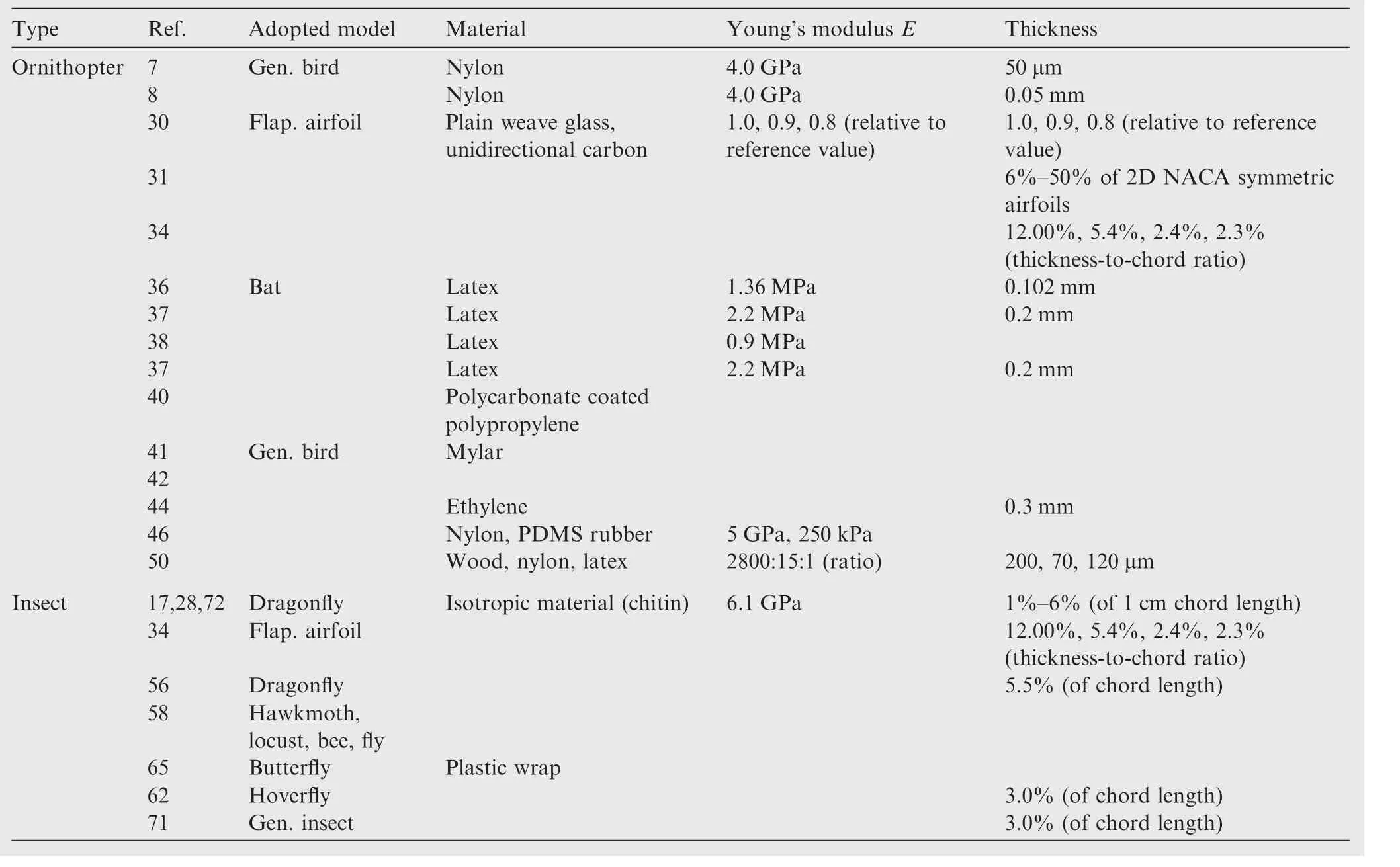
Table 3 Detail on membrane materials.

Table 4 Contributions of ornithopter's membrane wing structures.

Table 5 Contributions of insect's membrane wing structures.
2.6.1.Experimental approach
A summarized experimental research approaches towards the development of ornithopter- and insect-inspired MAVs as shown in Tables 6 and 7.Flight mode,wing planform,wingspan/AR,Re/velocity,k/St(Reynolds number,Re,reduced frequency,k,and Strouhal number,St)and focus have been listed for easy reference.
2.6.2.Numerical approach
A summarized numerical research approach towards the development of ornithopter- and insect-inspired MAVs is as shown in Tables 8 and 9.Flight mode,aerodynamic model,structural model,FSI related,and CFD software used by the authors have been listed for easy reference.
According to Tables 6–9,similar to previous analyses on flapping wing kinematics and membrane wing structures,both experimental and numerical research approaches toward ornithopter flight investigations are well-balanced.However,for insect flight investigations,numerical research approach is dominant over experimental research approach.This confirms the assumption of the inability to fabricate a reliable insect-type flapping wing prototype for experimental investigations,due to high mechanical complexities and very small size limitations.Therefore,a large number of numerical researches need to be conducted in order to gain better understanding of insect's flapping wing flight before a reliable prototype can be fabricated.In addition,numerical research approach is less likely to be costly and time-consuming.
2.7.Flapping wing mechanisms
Under this section,the types of mechanical flapping systems adopted in designing an effective propulsion con figuration for a flapping wing prototype fabrication are briefly reviewed.The latest flapping wing technologies are divided into two main categories:motorized transmission wings and piezoelectric transmission wings,which will be elaborated in separate sub-sections as shown below.
2.7.1.Motorized transmission wings
An effective mechanical flapping system is important in order to produce sufficient lift and thrust forces required for flying a flapping wing MAV.The term motorized refers to the dependence of a motor to supply the necessary driving force to perform flapping wing motion.For an ornithopter-type flapping wing flight,a simple four-bar crank rocker mechanism is commonly used to transform the rotational motion of an electric motor into a harmonic flapping motion.7,8,41,45,50A typical four-bar crank rocker mechanism is shown in Fig.1.7
When concerning a smaller size ornithopter,43,44or an insect with ornithopter-like flapping wing kinematics,such as a butterfly,65a smaller and more compact mechanical flapping system configuration than a four-bar crank rocker mechanism is required.Therefore,a slider crank is introduced,as shown in Fig.2.60
An effort on producing an effective mechanical flapping system for an insect flapping wing kinematics,typically a dragon fly,has been done,termed' modified slider crank'(MSC),which utilizes a rotary actuator to simultaneously generate active rotation and flapping of its wings.55This amazing innovation can be seen in Fig.3.54

Table 6 Ornithopter's summarized experimental research approaches.

Table 7 Insect's summarized experimental research approaches.
2.7.2.Piezoelectric transmission wings
As the demands on even smaller MAV rose,the fabrication process needs to be reconsidered and redesigned to accommodate all of the essential mechanisms into a very small body frame.It is undeniable that the motor mounted onto the MAV contributes the most weight and the vibration caused by the motor could be a possible factor of instability during flight.
Therefore,researchers need to find a better alternative solution in order to realize the fabrication of pico-aerial-vehicle (PAV).One of the most creative breakthroughs is the direct application of piezoelectric material substituting the heaviest and crucial part of an MAV,the motor itself.From here-onafter,the piezoelectric material used to produce flapping wing mechanism will be termed piezoelectric transmission.
As compared to motorized transmission,piezoelectric transmission generates an electrical field due to the chemical reaction that took place when external mechanical forces are applied onto the piezoelectric materials.Piezoelectric materials consist of specific solid materials such as crystals or ceramicswhich accumulates electrical charges when there is a form of mechanical force applied to the m.Vice versa,when an electrical field is applied,the piezoelectric materials will deform,producing effective displacement of about 0.1%.The deformation of the piezoelectric materials is called piezoelectric effect.

Table 8 Ornithopter's summarized numerical research approaches.
The effective displacement of utilizing''rawquot;piezoelectric materials will have limited capabilities and are not practical for most manufacturing application due to its minimal displacement percentage.Therefore,other than the application of''directquot;and''parallel pre-stressedquot;actuators,the displacement percentage can be amplified up to 1%or even more by taking advantage of the expansion of the piezoelectric materials(horizontal deformation)and the displacement amplifier mechanism(such as a resonant builder device).At resonance frequency,the implementation of piezoelectric materials as a substitution to conventional motor for flapping wing MAV applications can maximize the overall flapping angle as shown in Fig.4.73
The extensive uses of piezoelectric materials are limitless due to its robust deformation.Lee et al.mounted a flexible piezoelectric actuator underneath the wings of his ornithopter-type MAV to gain camber control during flapping flight.When an electrical field is fed,the actuator will deform and control the camber of the wings with its deformation(see Fig.5).74
Applications toward insect bio-mimicry have advanced tremendously to a very small size termed PAV.At this very small''statequot;,the contribution of individual parts towards overall weight is very crucial due to minimal payload and for a typical MAV,the motor will surely contribute the most weight.Therefore,replacing the motorized transmission with piezoelectric transmission is a beneficial modification at which not only the overall weight can be significantly reduced,but also the implementation of piezoelectric transmission can eliminate the need for sophisticated gears which reduces the power efficiency and accuracy of the motor as it transfers from one gear to another.
With the gears gone,the size of the body(the casing to cover the gear system)can be reduced as well,making the overall design of an MAV less bulky,achieve better aerodynamics,and achieve even smaller fabrication scale which suits the term pico(an even smaller scale than nano-aerial-vehicle (NAV)).Mateti et al.designed and fabricated a PAV termed LionFly which utilizes piezoelectric transmission wings with built-in flexure hinges to replace the need for gears and promote pas-sive wing rotation as shown in Figs.6 and 7.73,75A previous research by Sreetharan and Wood has seen the same concept but with different designs as shown in Fig.8.76Research on materials used to fabricate wings that are mounted onto the piezoelectric transmission has also been conducted by Tanaka et al.as shown in Fig.9.77

Table 9 Insect's summarized numerical research approaches.

Fig.1 Typical four-bar crank rocker mechanism.7

Fig.2 Slider crank mechanism.60

Fig.3 Modified slider crank mechanism.54
Later on,the application of piezoelectric materials was implemented as an alternative flapping wing transmission system for the tandem configuration flapping wing unmanned aerial vehicles as well.Kumar and Hu78conducted an experimental research on the tandem piezoelectric flapping wings to investigate the wake flow characteristics of such flapping wing configuration based on a series of preliminary works related to tandem piezoelectric flapping wings' flow structures.79,81

Fig.4 Wing motion at static position and resonance condition(75 V,45 Hz).73

Fig.5 Application of flexible piezoelectric actuator for camber control.74
Most importantly,piezoelectric materials was introduced into the field of flapping wing unmanned aerial vehicles smaller than MAV (NAV/PAV) as a new form of transmission in order to replace previously developed motorized transmission which contributes too much weight,consumes a lot of space,rigorously vibrates if mounted on smaller scale unmanned vehicles,and presents high fabrication complexity due to gear mechanisms.The simplicity of implementing piezoelectric transmission as compared to motorized transmission can even be observed physically without detailing each individual,functional part.Fig.10 shows the physically observable simplicity of piezoelectric transmission compared to motorized transmission.

Fig.6 Conceptual drawing of LionFly.75

Fig.7 Photograph of LionFly prototype LF07.73

Fig.8 Insect-type flapping wing MAV design.76
From the comparison shown in Figs.6,7 and 10,it has been proven that a motorized transmission flapping wing system is too bulky to be mounted on a tiny bio-mimicry body frame and the smallest motor available and easily obtained from local distributors is the pager motor,which overloads the tiny body frame in more ways than one.The advantages of utilizing a piezoelectric transmission can be divided into two categories;direct advantages and supporting advantages.The direct advantages are small,light,simple arrangement,simple to operate,superb accuracy,and no gears are needed.Furthermore,the secondary advantages are directly related to the fact that small size unmanned aerial vehicles will have small wings with small aspect ratios and are subjected to complex,unsteady,and low Reynolds number flow field.Therefore,high wing flapping frequency is required to produce enough lift and thrust forces for flapping flight,which piezoelectric transmissions can definitely deliver.82This technology has yet to be fully applied on a larger scale such as to an MAV.With all the advantages overshadowing the disadvantages,it is not impossible to take advantage of this technology and redefine the core of MAV technology where payload limitation will be lifted and the transition-Reynolds-regime duelers such as small ornithopters and large insects(MAV based on hummingbirds are barely revealed to the public and little research data are known)can be realized with an efficient pair of transition-flow field-manipulating wings.The comparisons between motorized and piezoelectric transmission wings are essential in order to discretize the advantages and disadvantages of each transmission before designing a blueprint.

Fig.9 Photos of fabricated corrugated wings(CFRP=carbon fiber reinforced polymer).77
Motorized transmission wings are mostly used for large to medium-size UAVs(MAVs are subjected to 15 cm wingspan length limitation),bulky(the conventional motor adds up a lot of the total mass of the MAV),and noisy.Furthermore,more gears/mechanical parts need to be considered to tune the torque power/frequency as the torque/frequency is nontunable.By using motorized transmission wings,an MAV will be able to propel heavier wing load(therefore,higher inertial effects)but will be unable to operate at Nano-precision.The wings are typically made from non-conductive materials carbon fiber.
Piezoelectric transmission wings are applied for nano-to pico-scale UAV(existed because of space and size limitations;deforms/bends and stretches to produce flapping motion of attached wings),does not require a motor,and less noisy(detectable noise only at high frequency).Furthermore,no gears are required(only the piezoelectric material and the wing structure are required,which the wing structure can be from the same material as the piezoelectric material)and torque/frequency is tunable due to adjustable electrical current input.By using piezoelectric transmission wings,an MAV will be able to effectively propel small scale wings with Nano-precision(such as insect wings due to small aspect ratio,light,thin,and low inertial effects).On the other hand,if the wings are made with the same material as the piezoelectric material,the y might be exposed to electrical surge and durability against harsh weather is questionable(heat/cold/sandy).
2.8.significant difference in flapping wing flow patterns
According to the research references reviewed,the utilization of vortices occurring on either the leading edge(LE)or trailing edge(TE)have been tremendously leaning towards insectinspired researches.It is well understood that ornithopters does not significantly utilize LE and TE vortices as the vortices decay(the occurrence of vortex-shedding)at the wake of the ornithopters' flapping wings.Furthermore,wing tip vortices have a more significant effect towards ornithopter-type flapping wing motion as portrayed by Tsai and Fu44and Fujikawa et al.65;the latter proves that butterflies(ornithopter-like flapping wing motion),with elastic membrane wings,generate effective separation vortices and utilize those wing tip vortices to produce large lift.Fig.11 below shows examples of wing tip velocity vector44and pressure contour65diagrams.

Fig.10 Physical observation of motorized transmission wings.

Fig.11 Velocity vector44and pressure contour65during downstroke.
The LE and TE vortices do not significantly affect aerodynamic forces produced by ornithopter's flight as much as the y do towards insect's flight due to a lot of criteria;insects flap its wings multiple times faster than ornithopters and it has the ability to achieve motionless hover(flapping motion is almost fully horizontal)with large angles of incidence,26,62,70insects have a unique corrugated wing profile,28,70and dragonflies even have tandem wing configuration to promote wing-wing(fore-and hind-wings)26,28and vortex-vortex(constructive or destructive)26interactions.Therefore,insectstake better advantage of utilizing LE and TE vortices to produce aerodynamic forces than ornithopters.Lian et al.28have done a very thorough review on the characterization of tandem and corrugated wings and Shyy et al.29have systematically summarized recent progress in flapping wing aerodynamics and aeroelasticity,which will not be explained in this review paper as details of their researches can be obtained from their original review papers,respectively.Fig.12 below shows examples offlow patterns and vortex structures of corrugated and tandem wing configuration.
2.9.Other important aspects
There are other important aspects or parameters which have to be considered in the research field of flapping wing MAV.These 'dimensionless' parameters are the fundamentals of MAV research,in which these dimensionless parameters define the relevance of the termed 'micro' and the application of such small 'aerial vehicles' under low influence of wind speed.These dimensionless parameters are Reynolds number,Re,reduced frequency,k,and Strouhal number,St.

Fig.12 Vorticity contour of tandem wings,27streamline around corrugated profile,27velocity vector of tandem wings81and vorticity plots of corrugated model wing.85
Re is the most important dimensionless parameters which defines and differentiates the flow field regime of which an aerial vehicle will have to fly through and effectively manipulate the flow field characteristics to produce constructive aerodynamic forces in order to keep it a float and maintain flying performance.Inspired by natural fliers(birds and insects),a flapping wing MAV can effectively manipulate the low Re flow field in its environment to its advantage by generating lift,thrust,and drag forces to sustain its flight state,whether for hovering of forward flight.Natural fliers are experts in highspeed maneuvers under very low Re condition.As reported by Park and Yoon,45large birds have a wing chord Re larger than 15000 but still within 1X10⁵range,small birds to large insects having Re between 1000 and 15000,and small insects having Re between 100 and 1000.Fig.13 shows a plotted Reynolds number versus wing length graph.45

Fig.13 Reynolds number vs wing length.45
A benchmark can be summarized to point out the obvious line of differences and possible intersection and interaction between species(birds/bird-like and insects/insect-like)and its respective flight type(ornithopter,ornithopter-like,insect,and insect-like).These differences in species-flight type swapping can be significant in narrowing the specific needs of a research based on proven facts and figures of previous researches.As seen in Table 10,guidelines are made for flight type,wing kinematics,and Reynolds number for each respective species,which suggest a significant relationship between the size of a species and the wing kinematics it adopts to be able to fly within specific Reynolds number regime.
As seen in Table 10,the Reynolds number approximation is in good agreement with Park's report.The intersection area where ornithopter's and insect's species and flight type swapped falls within the ''small birds to large insectsquot;Reynolds number regime.This indicates that large insects might have had adopted specific ornithopter-like flight characteristics to enable the m to fly within the ''transition-dominatedquot;Reynolds number regime.
Each research should be classified as detailed as possible.For example,to create a large size insect-type flapping wing MAV,one must understand that the wing aerodynamics of the MAV should be able to withstand the air flow characteristics presented by the Reynolds number regime it flies in by utilizing its complex 3 DOF wing kinematics.Vice versa,to create a small size ornithopter-type flapping wing MAV,one must be able to anticipate the unsteady air flow characteristics and to utilize those characteristics to the MAV's advantages;the latter proves to be much more difficult to accomplish using a 2 DOF wing kinematics,with the third DOF limited to the capability of the MAV's wing to passively rotate its flexible membrane structure.
Therefore,as summarized in Table 8,a hypothesis can be made,that the insect flight type and insects with ornithopterlike flight type can withstand unsteady air flow characteristicsand achieve better flight performance within Reynolds number range of 1000–15000 as compared to small birds(small size ornithopter flight type MAV).Therefore,in order to survive,small birds possesses insect-like flight type with 3 DOF wing kinematics for better flight efficiencies,as demonstrated by the flight of hummingbirds.29,66,67Details regarding Re analysis and comparison presented in this review are brief and only serve as a simple reference.Further analysis and in-depth details are required to properly address the importance of Re,thus,future works are necessary.

Table 10 Summarized guidelines.
Reduced frequency is also an important dimensionless parameter which characterizes the unsteadiness of flapping motions caused by a complicated mix of periodic pitching,plunging,and surging(horizontal motion).28Smaller birds tend to have higher reduced frequencies and fly under more unsteady flow conditions than larger birds due to higher flapping rate/lower flight velocity.83
Further explained by Lian et al.,28the Strouhal number,which is another important dimensionless parameter,is often used as a measure of flight efficiency.As cited from Taylor et al.,84the Strouhal number of 42 different species of bats,birds,and insects in cruise flight fell within a narrow range between 0.2 and 0.4,which indicates that the Strouhal number can be used as a guideline for flapping wing design efficiency optimizations.Therefore,reduced frequency and Strouhal number,as well as Reynolds number,have proven to be an important set of dimensionless parameters and are worth of future reviews.
3.Critical issues
Micro-aerial-vehicle researches are still ongoing and rapidly growing.As research extends towards new ground,issues will definitely be addressed in parallel with the depth of the research.Issues which are deemed critical and require further research are listed as follows:
(1)Most of the researches conducted for ornithopter-and insect-type flapping wing MAV,either experimental or n
umerical,consider the wings to be an isolated case,where the influence of the flapping wing motion towards other parts of the MAV's body and vice versa,are neglected for calculation simplicity.Multi-body dynamics are addressed in a limited number of research papers such as by Grauer et al.11and Pfeiffer et al.,52which require further investigations for better understanding of its nature.
(2)Most researches neglect the mass of the wings in which the consideration of wing's mass could significantly affect the stability,orientation,aerodynamic performance,and flight trajectory of an MAV.58
(3)Inherent stability during flight is still an issue.Most MAVs use complex control systems and actuations to maintain its stability in mid-air,which require multiple expertise and high expenses.More researches on inherent stability such as by Phan et al.64are needed.
(4)Research on transition flight,such as from hover mode to forward flight mode,from rest mode to flight mode(take-off),from flight mode to rest mode(landing),or from walking mode to flight mode and vice versa,is currently limited as well.Bachmann et al.40and Shin et al.85did design MAVs capable of transition flight but none of the m applied flapping wing system.
(5)Limited research is available on small scale ornithoptertype MAVs.Research is either focused on standard/large sized ornithopter-type MAVs orinsect-type MAVs.A magpie-inspired flapping wing MAV has been conducted by Pfeiffer et al.52More research is needed to support future development.
(6)Research on MAV endurance towards harsh environments is limited to gust environment only.27,28Limited or no research has been conducted for endurance testing towards other types of harsh environments such as rain,snow,or even sandstorm.
(7)Breakthrough piezoelectric application discoveries are limited to Nano-and Pico-scale unmanned vehicles due to size minimization demands.73,75Utilization of piezoelectric transmission on MAVs is yet to be fully understood as researches on the particular application,such as a research done by Sreetharan and Wood,76are limited.
(8)FSI implementations are also limited.The current number of research done using FSI approach is still insufficient for us to truly understand the nature of coupled software.
4.Recommendations
Research on the development of MAV has been conducted for a very long time but there is still a lot of room available for improvements.Recommendations to overcome the stated issues in Section 2.8 and other additional recommendations for future development of MAV are as listed below:
(1)Multi-body dynamics research needs to grow as it is important to consider every part of an MAV in determining a more accurate stability and aerodynamic performance analyses.
(2)Similar to multi-body dynamics research,future MAV research should include the mass of the wings in determining a more accurate stability,orientation,aerodynamic performance,and flight trajectory of a MAV.Thus,future research is still in need of multi-body dynamics and wings' mass related analyses.
(3)Inherent stability is also a wide open research area.Research regarding inherent stability during flight is very important in order to simplify the flapping wing system,minimize expertise required to design and fabricate an MAV,and reduces fabrication cost.
(4)Room for improvements are also available for MAV innovations such as multi-purpose micro-aerial-landvehicle (MALV)40and wall-climbing MAV.85
(5)Future research on small scale ornithopter-type MAVs is very important in order to satisfy size limitation without sacrificing the simplicity of an ornithopter's flapping wing mechanism and aerodynamic characteristics.
(6)The endurance of a MAV should be further tested in different harsh environments such as rain,snow,and even sandstorm in order to produce an all-weather MAV.
(7)FSI is also a potential research area because it is a newly adopted methodology.Using FSI approach,the effects of air flow towards wing structure can be simultaneously quantified with the effects of wing structure towards airflow characteristics.
(8)Future research is also open for further development of a control scheme inspired by human memory and learning concept for wing motion control of MAVs such as by Song et al.67
(9)Adopting piezoelectric transmission system could significantly reduce the overall weight of a typical motorized transmission MAV and presents a very simple piezoelectric effect mechanism which does not require complex geared automations while saving up storage space.Therefore,the required lift and thrust forces of such MAV to counteract its own weight in order to hover and fly forward will be reduced desirably.In addition,the extra payload and storage capacities available will enable multiple mounts of better performing devices such as high-definition cameras and sensors.
(10)A three-dimensional mechanism may be extended further to provide a more accurate quantitative experimental flapping data to gain further understanding of avian flight.80
(11)The investigation of the flow analysis of the flapping wing can be performed by particle image velocimetry (PIV) techniques technology.86
(12)A more powerful computer is required given that the flapping wing must be developed in a fine mesh to avoid lower memory problem and obtain accurate results.86
5.Conclusions
A review on flapping wing micro-aerial-vehicle of both ornithopter-and insect type flapping wing flights has been conducted.The contribution ornithopter-and insect-type flapping wing kinematics and membrane wing structures have been summarized and presented systematically in table form.General guidelines have been presented as well to aid in narrowing the scope of research and to determine specific approaches.As a conclusion from the guidelines,a possible scope for future MAV development has been determined.Issues of which previous researchers have come upon have been listed for future reference and await further improvements.All in all,this review paper provides a new set of references which can be beneficial for literature reviews of future researches.
Acknowledgments
The authors wish to thank all contributing researchers for their enthusiastic effort in realizing the potential of bio-mimicry in unmanned aerial vehicles' development of all sizes and all the feedbacks given to support the production of this review,as recognized in the figures and tables.
1.Collis SS,Joslin RD,Seifert A,Theo filis V.Issues in active flow control:theory,control,simulation,and experiment.Prog Aerosp Sci 2004;40(4):237–89.
2.Strang KA.Efficient flapping flight of pterosaurs [dissertation].Stanford:Stanford University;2009.
3.JackowskiZJ.Design amp; construction of an autonomous ornithopter [dissertation].MA:Massachusetts Institute of Technology;2009.
4.Bunget G. BATMAV a bio-inspired micro-aerial vehicle for flapping flight [dissertation].NC:North Carolina State University;2010.
5.Bansmer S,Radespiel R,Unger R,Haupt M,Horst P.Experimental and numerical fluid–structure analysis of rigid and flexible flapping airfoils.AIAA J 2010;48(9):1959–74.
6.Gomes JP,Yigit S,Lienhart H,Schaefer M.Experimental and numerical study on a laminar fluid–structure interaction reference test case.J Fluids Struct 2011;27(1):43–61.
7.Mazaheri K,Ebrahimi A.Experimental investigation on aerodynamic performance of a flapping wing vehicle in forward flight.J Fluids Struct 2011;27(4):586–95.
8.Mazaheri K,Ebrahimi A.Experimental investigation of the effect of chordwise flexibility on the aerodynamics of flapping wings in hovering flight.J Fluids Struct 2010;26(4):544–58.
9.Mazaheri K,Ebrahimi A.Optimization of the cruise flight dynamics of a flapping wing vehicle based on experimental aerodynamic data.J Aerosp Eng ASCE 2012;25(1):101–7.
10.Li Y,Nahon M.Modeling and simulation of nonlinear dynamics of flapping wing MAV.AIAA J 2011;49(5):969–81.
11.Grauer Jr JA,Hubbard JE.Multibody model of an ornithopter.J Guid,Control,Dynam 2009;32(5):1675–9.
12.Grauer Jr JA,Hubbard JE.Inertial measurements from flight data of a flapping-wing ornithopter.J Guid,Control,Dynam 2009;32(1):326–31.
13.De Croon GCHE,de Clerq KME,Ruijsink R,Remes B,de Wagter C.Design,aerodynamics,and vision-based control of the DelFly.Int J Micro Air Veh 2009;1(2):71–97.
14.Nagai H,Isogai K,Fujimoto T,Hayase T.Experimental and numerical study of forward flight aerodynamics of insect flapping wing.AIAA J 2009;47(3):730–42.
15.Liu H,Aono H.Size effects on insect hovering aerodynamics:an integrated computational study.Bioinsp Biomim 2009;4(1):015002-1–0150021-3.
16.Zhang YL,Wu JH,Sun M.Lateral dynamic flight stability of hovering insects:theory vs numerical simulation.Acta Mech Sin 2012;28(1):221–31.
17.Hord K,Lian Y.Numerical investigation of the aerodynamic and structural characteristics of a corrugated airfoil.J Aircr 2012;49(3):749–57.
18.Kim WK,Ko JH,Park HC,Byun D.Effects of corrugation of the dragonfly wing on gliding performance.J Theoret Biol 2009;260(4):523–30.
19.Levy DE,Seifert A. Simplified dragonfly airfoil aerodynamics at Reynolds numbers lowers than 8000.J Phys Fluid 2009;21(7):071901-1–071901-17.
20.Levy DE.Flow features of a schematic dragonfly airfoil at glid [dissertation].Tel-Aviv:Tel-Aviv University;2010.
21.Murphy J,Hu H.An experimental investigation on a bio-inspired corrugated airfoil.Report No.:AIAA-2009-1087.Reston:AIAA;2009.
22.Broering T,Lian Y.The effect of phase angle and wing spacing on tandem flapping wings.Acta Mech Sin 2012;28(6):1557–71.
23.Broering T,Lian Y,Henshaw W.Numerical investigation of energy extraction in a tandem flapping wing configuration.AIAA J 2012;50(11):2295–308.
24.Zhang G.Unsteady aerodynamics of a morphing tandem wing UAV.J Aircr 2012;49(5):1315–23.
25.English TG,Simpson JR,Landman D,Parker PA.An efficient split-plot approach for modeling nonlinear aerodynamic effects.Qual Eng 2012;24(4):522–30.
26.Sun M,Lan SL.A computational study of the aerodynamic forces and power requirements of dragonfly(Aeschna juncea)hovering.J Exp Biol 2004;207(11):1887–901.
27.Prater R,Lian Y.Aerodynamic response of stationary and flapping wings in oscillatory low Reynolds number flows.Report No.:AIAA-2012-0418.Reston:AIAA;2012.
28.Lian Y,Broering T,Hord K,Prater R.The characterization of tandem and corrugated wings.Prog Aerosp Sci2013;65(1):41–69.
29.Shyy W,Aono H,Chimakurthi SK,Trizila P,Kang CK,Cesnik CES,et al.Recent progress in flapping wing aerodynamics and aeroelasticity.Prog Aerosp Sci 2010;46(7):284–327.
30.Unger R,Haupt MC,Horst P,Radespiel R.Fluid–structure analysis of a flexible flapping airfoil at low Reynolds number flow.J Fluids Struct 2012;28(1):72–88.
31.Ashraf MA,Young J,Lai JCS.Reynolds number,thickness and camber effects on flapping airfoil propulsion.J Fluids Struct 2011;27(2):145–60.
32.Benkherouf T,Mekadem M,Oualli H,Hanchi S,Keirsbulck L,Labraga L.efficiency of an auto-propelled flapping airfoil.J Fluids Struct 2011;27(4):552–66.
33.Amiralaei MR,Alighanbari H,Hashemi SM.Flow field characteristics study of a flapping airfoil using computational fluid dynamics.J Fluids Struct 2011;27(7):1068–85.
34.Srinath DN,Mittal S.Optimal aerodynamic design of airfoils in unsteady viscous flows.Comp Meth Appl Mech Eng 2010;199(29):1976–91.
35.Amiralaei MR,Alighanbari H,Hashemi SM.An investigation into the effects of unsteady parameters on the aerodynamics of a low Reynolds number pitching airfoil.J Fluids Struct 2010;26(6):979–93.
36.Hubner JP,Hicks T.Trailing-edge scalloping effect on flat-plate membrane wing performance.Aerosp Sci Technol 2011;15(8):670–80.
37.Rojratsirikul P,Genc MS,Wang Z,Gursul I.Flow-induced vibrations of low aspect ratio rectangular membrane wings.J Fluids Struct 2011;27(8):1296–309.
38.Molki M,Breuer K.Oscillatory motions of a prestrained compliant membrane caused by fluid–membrane interaction.J Fluids Struct 2010;26(3):339–58.
39.Rojratsirikul P,Wang Z,Gursul I.Effect of pre-strain and excess length on unsteady fluid–structure interactions of membrane airfoils.J Fluids Struct 2010;26(3):359–76.
40.Bachmann RJ,Boria FJ,Vaidyanathan R,Ifju PG,Quinn RD.A biologically inspired micro-vehicle capable of aerial and terrestrial locomotion.Mech Mach Theory 2009;44(3):513–26.
41.Pourtakdoust SH,Aliabadi SK.Evaluation of flapping wing propulsion based on a new experimentally validated aeroelastic model.Sci Iran,Trans B:Mech Eng 2012;19(3):472–82.
42.Djojodihardjo H,Ramli ASS,Wiriadidjaja S.Kinematic and aerodynamic modelling of flapping wing ornithopter.Proc Eng 2012;50(1):848–63.
43.Lee JS,Kim JK,Han JH,Ellington CP.Periodic tail motion linked to wing motion affects the longitudinal stability of ornithopter flight.J Bion Eng 2012;9(1):18–28.
44.TsaiBJ,FuYC.Design and aerodynamic analysis of a flapping-wing micro aerial vehicle.Aerosp Sci Technol 2009;13(7):383–92.
45.Park JH,Yoon KJ.Designing a biomimetic ornithopter capable of sustained and controlled flight.J Bion Eng 2008;5(1):39–47.
46.Heathcote S,Wang Z,Gursul I.Effect of spanwise flexibility on flapping wing propulsion.J Fluids Struct 2008;24(2):183–99.
47.Perez-Rosado A,Philipps A,Barnett E,Roberts L,Gupta SK,Bruck HA.Compliant multifunctional wing structures for flapping wing MAVs.The Society for Experimental Mechanics,Inc.;2014.
48.Gerdes JW,Cellon KC,Bruck HA,Gupta SK.Characterization of the mechanics of compliant wing designs for flapping-wing miniature air vehicles.Exp Mech 2013;53(9):1561–71.
49.Whitney JP,Wood RJ.Aeromechanics of passive rotation in flapping flight.J Fluid Mech 2010;660(1):197–220.
50.Hu H,Kumar AG,Abate G,Albertani R.An experimental investigation on the aerodynamic performances of flexible membrane wings in flapping flight.Aerosp Sci Technol 2010;14(8):575–86.
51.Kim SW,Jang LH,Kim MH,Kim JS.Power-driven ornithopter piloted by remote controller.United States patent US 6550716 B1.2003.
52.Pfeiffer AT,Lee JS,Han JH,Baier H.Ornithopter flight simulation based on flexible multi-body dynamics.J Bion Eng 2010;7(1):102–11.
53.Su JY,Yang JT.Analysis of the aerodynamic force in an eyestabilized flapping flyer.Bioinspir Biomim 2013;8(4):1–8.
54.DeLaurier JD.An aerodynamic model for flapping wing flight.Aeronaut J R Aeronaut Soc 1993;97(964):125–30.
55.Fenelon MAA,Furukawa T.Design of an active flapping wing mechanism and a micro aerial vehicle using a rotary actuator.Mech Mach Theory 2010;45(2):137–46.
56.Levy DE,Seifert A.Parameter study of simplified dragonfly airfoil geometry at Reynolds number of 6000.J Theoret Biol 2010;266(4):691–702.
57.Hamamoto M,Kotani T,Nakano I,Ohta Y,Hara K,Murakami T,Hisada T.Investigation on force transmission of direct-drive thorax unit with four ultrasonic motors for a flapping micro aerial vehicle.Adv Robot 2014;28(3):133–44.
58.Orlowski CT,Girard AR.Dynamics,stability,and control analyses of flapping wing micro-air vehicles.Prog Aerosp Sci 2012;51(1):18–30.
59.Nguyen TT,Byun D.Two-dimensional aerodynamic models of insect flight for robotic flapping wing mechanisms of maximum efficiency.J Bion Eng 2008;5(1):1–11.
60.Sun M,Xiong Y.Dynamic flight stability of a hovering bumblebee.J Exp Biol 2005;208(3):447–59.
61.Sun M,Wang JK.Flight stabilization control of a hovering model insect.J Exp Biol 2007;210(15):2714–22.
62.Du G,Sun M.Effects of wing deformation on aerodynamic forces in hovering hoverflies.J Exp Biol 2010;213(13):2273–83.
63.Mou XL,Liu YP,Sun M.Wing motion measurement and aerodynamics of hovering true hoverflies. J Exp Biol 2011;214(17):2832–44.
64.Phan HV,Nguyen QV,Truong QT,Truong TV,Park HC,Goo NS,et al.Stable vertical takeoff of an insect-mimicking flappingwing system without guide implementing inherent pitching stability.J Bion Eng 2012;9(4):391–401.
65.Fujikawa T,Hirakawa K,Okuma S,Udagawa T,Nakano S,Kikuchi K.Development of a small flapping robot Motion analysis during takeoff by numerical simulation and experiment.Mech Syst Sig Process 2008;22(6):1304–15.
66.Rakotomamonjy T,Ouladsine M,Moing TL.Longitudinal modeling and control of a flapping-wing micro aerial vehicle.Control Eng Pract 2010;18(7):679–90.
67.Song YD,Weng L,Lebby G.Human memory/learning inspired control method for flapping-wing micro air vehicles.J Bion Eng 2010;7(2):127–33.
68.Chang K,Rue J,Ifju P,Haftka R,Schmitz T,Tyler C,et al.Analysis of thrust production in small synthe tic flapping wings.The Society for Experimental Mechanics,Inc.;2014.
69.Mahjoubi H,Byl K.efficient flight control via mechanical impedance manipulation:energy analyses for hummingbirdinspired MAVs.J Intell Robot Syst 2014;73(1):487–512.
70.Meng XG,Xu L,Sun M.Aerodynamic effects of corrugation in flapping insect wings in hovering flight.J Exp Biol 2011;214(3):432–44.
71.Orlowski CT,Girard AR.Modeling and simulation of nonlinear dynamics of flapping wing micro air vehicles.AIAA J 2011;49(5):969–81.
72.Kesel AB,Philippi U,Nachtigall W.Biomechanical aspects of the insect wing:an analysis using the finite element method.Comp Biol Med 1998;28(4):423–37.
73.Mateti K,Byrne-Dugan RA,Rahn CD,Tadigadapa SA.Monolithic SUEX flapping wing mechanisms for pico air vehicle applications.J Microelectromech Syst 2013;22(3):527–35.
74.Lee JS,Han JH,Kim DK.Camber-adjustable flapping wing air vehicles.8th international conference on ubiquitous robots and ambient intelligence(URAI);2011.
75.Mateti K,Byrne-Dugan RA,Rahn CD,Tadigadapa A.Wing rotation and lift in SUEX flapping wing mechanisms.Smart Mater Struct 2013;22(1):1–11.
76.Sreetharan PS,Wood RJ.Passive torque regulation in an underactuated flapping wing robotic insect.Auton Robots 2011;31(2):225–34.
77.Tanaka H,Whitney JP,Wood RJ.Effect of flexural and torsional wing flexibility on lift generation in hoverfly flight.Integ Comp Biol 2011;51(1):142–50.
78.Kumar AG,Hu H.An experimental investigation on the wake flow characteristics of tandem flapping wings.6th AIAA theoretical fluid mechanics conference.Reston:AIAA;2011.
79.Clemons L,Igarashi H,Hu H.An experimental study of unsteady vortex structures in the wake of a piezoelectric flapping wing.48th AIAA aerospace sciences meeting including the new horizons forum and aerospace exposition.Reston:AIAA;2010.
80.Wang K,Vaidya U,Ganapathysubramanian B,Hu H.Experimental data analysis of the vortex structures in the wakes of flapping wings.28th AIAA applied aerodynamics conference.Reston:AIAA;2010.
81.Kumar AG,Hu H.Flow structures in the wakes of tandem piezoelectric flapping wings.28th AIAA applied aerodynamics conference.Reston:AIAA;2010.
82.Bidakhvidi MA,Shirzadeh R,Steenackers G,Vanlanduit S.Experimental study of the flow field induced by a resonating piezoelectric flapping wing.Exp Fluids 2013;54(11):327–35.
83.Shyy W,Berg M,Ljungqvist D.Flapping and flexible wings for biological and micro air vehicles.Prog Aerosp Sci 1999;35(5):455–505.
84.Taylor GK,Nudds RL,Thomas ALR.Flying and swimming animals cruise at a Strouhal number tuned for high power efficiency.Nature 2003;425(6959):707–11.
85.Shin JU,Kim D,Kim JH,Myung H.Micro aerial vehicle type wall-climbing robot mechanismIEEE RO-MAN:the 22nd IEEE international symposium on robot and human interactive communication.Piscataway(NJ):IEEE Press;2013.
86.Yusoff H.Experimental and numerical investigations on the performance of flexible skin flapping wing for micro aerial vehicle application[dissertation].Penang:Universiti Sains Malaysia;2013.
Kamarul Arifin Bin Ahmadis an associate professor and Ph.D.supervisor at the Department of Aerospace Engineering,Faculty of Engineering,Universiti Putra Malaysia(UPM),Malaysia.He received his Ph.D.degreefrom Queen's University of Belfast in 2006.His main research interests are aerodynamics and computational fluid dynamics(CFD).
6 July 2015;revised 27 July 2015;accepted 22 August 2015
Available online 27 August 2016
Flapping wing kinematics;Insect;
Membrane wing;
Micro-air-vehicle;
Ornithopter
©2016 Chinese Society of Aeronautics and Astronautics.Production and hosting by Elsevier Ltd.This is an open access article under the CC BY-NC-ND license(http://creativecommons.org/licenses/by-nc-nd/4.0/).
*Corresponding author.
E-mail address:aekamarul@upm.edu.my(K.A.Bin Ahmad).Peer review under responsibility of Editorial Committee of CJA.
 CHINESE JOURNAL OF AERONAUTICS2016年5期
- CHINESE JOURNAL OF AERONAUTICS的其它文章
- A new non-linear vortex lattice method:Applications to wing aerodynamic optimizations
- Experimental study of flow field distribution over a generic cranked double delta wing
- Streamwise-body-force-model for rapid simulation combining internal and external flow fields
- An artificial neural network approach for aerodynamic performance retention in airframe noise reduction design of a 3D swept wing model
- effects of wing locations on wing rock induced by forebody vortices
- Turbulent boundary layer separation control using plasma actuator at Reynolds number 2000000