
A new non-linear vortex lattice method:Applications to wing aerodynamic optimizations
2016-11-24 02:23OliviuSugarGaborAndreeaKoreanschiRuxandraMihaelaBotez
CHINESE JOURNAL OF AERONAUTICS 2016年5期
Oliviu Sugar Gabor,Andreea Koreanschi,Ruxandra Mihaela Botez
LARCASE Laboratory of Applied Research in Active Controls,Avionics and Aeroservoelasticity,E´cole de Technologie Supe´rieure,1100 rue Notre Dame Ouest,Montre´al H3C1K3,Que´bec,Canada
A new non-linear vortex lattice method:Applications to wing aerodynamic optimizations
Oliviu Sugar Gabor,Andreea Koreanschi,Ruxandra Mihaela Botez*
LARCASE Laboratory of Applied Research in Active Controls,Avionics and Aeroservoelasticity,E´cole de Technologie Supe´rieure,1100 rue Notre Dame Ouest,Montre´al H3C1K3,Que´bec,Canada
This paper presents a new non-linear formulation of the classical Vortex Lattice Method(VLM)approach for calculating the aerodynamic properties of lifting surfaces.The method accounts for the effects of viscosity,and due to its low computational cost,it represents a very good tool to perform rapid and accurate wing design and optimization procedures.The mathematical model is constructed by using two-dimensional viscous analyses of the wing span-wise sections,according to strip theory,and the n coupling the strip viscous forces with the forces generated by the vortex rings distributed on the wing camber surface,calculated with a fully three-dimensional vortex lifting law.The numerical results obtained with the proposed method are validated with experimental data and show good agreement in predicting both the lift and pitching moment,as well as in predicting the wing drag.The method is applied to modifying the wing of an Unmanned Aerial System to increase its aerodynamic efficiency and to calculate the drag reductions obtained by an upper surface morphing technique for an adaptable regional aircraft wing.
1.Introduction
The air transportation industry is a commercial and economical sector with a very fast growth rate.The International Civil Aviation Organization(ICAO)estimates that the number offlights will triple by 2040.1This growth rate,together with growing global concern for environmental protection and the reduction of greenhouse gas emissions obliges the aerospace industry to search for solutions to improve aircraft efficiency.
One possibility for achieving this desired efficiency is wing morphing,through its active and controlled modification of one or several wing geometrical characteristics during flight.Researchers have proposed different technological solutions for obtaining the desired wing adaptability,with some concepts achieving significant performance improvements with respect to the baseline design.Sofla et al.2,Stanewsky3or Barbarino et al.4presented exhaustive reviews on the research performed on various morphing wing technologies,both by academia and by the aerospace industry.Morphing wings were used to adapt the wing span and airfoil camber,5,6the winglet cant and toe angles,7to replace conventional high-lift devices,8–10or the conventional control surfaces.11
In Canada,the CRIAQ 7.1 project,a collaboration between Ecole de Technologie Superieure,Ecole Polytechnique de Montreal,Bombardier Aeronautique,Thales Canada and the Institute for Aerospace Research–Canada National Research Council took place between 2006 and 2009.The objective of this project was to improve and control the flow laminarity over a morphing wing wind tunnel model,in order to obtain significant drag reductions.12The wing was equipped with a flexible composite material upper surface whose shape could be changed using internally-placed Shape Memory Alloy(SMA)actuators.13The numerical study revealed very promising results:the morphing system was able to delay the transition location downstream by up to 30%of the chord and reduce the airfoil drag by up to 22%.14The actuator optimal displacements for each flight condition were provided by using both a direct open loop approach15,16and a closed loop configuration based on real time pressure readings from the wing upper surface.17,18In addition,a new controller based on an optimal combination of the bi-positional and PI laws was developed.19,20The wind tunnel tests were performed in the 2 m by 3 m atmospheric closed circuit subsonic wind tunnel at IAR-CNRC,and validated the numerical wing optimisations21and designed control techniques.22
Recently,research on the capabilities of morphing wings equipped with flexible upper surfaces included the optimization of the ATR42 regional aircraft airfoil23and of the Hydra Technologies S4 Unmanned Aerial System(UAS)airfoil.24Both cases obtained notable transition delays of up to 20%of the chord and significant drag reductions of up to 15%.The morphing system designed for improving and controlling the laminarity of the flow could also provide performance improvements at high angles of attack.For the UAS-S4 airfoil,a 2°increase of the stall angle,with a corresponding increase of the maximum lift coefficient by 6%have been obtained,using the morphing upper skin to delay the boundary layer separation.25
In order to obtain three-dimensional wing performance improvements with upper surface morphing,a fast and efficient aerodynamic solver was required.A three-dimensional,non-linear numerical extension of the classic lifting line theory,coupled with a two-dimensional viscous flow solver,gave sufficiently accurate estimations of the aerodynamic characteristics of the UAS-S4wing.26A study of the UAS-S4 wing revealed that for typical cruise and surveillance flight conditions,the morphing wing could provide drag reductions of up to 5%.27Further research was performed to determine the influence of the number of internally-placed actuators and their positions along the wing span on the aerodynamic gains.The aerodynamic calculations were done using the numerical non-linear lifting line code,while the optimized upper skin shapes were determined by a novel technique based on a hybrid Artificial Bee Colony (ABC) and the Broyden-Fletcher-Goldfarb-Shanno (BFGS) algorithm.28
The CRIAQ MDO 505 project is a continuation of the CRIAQ 7.1 project and is centered on the implementation of the adaptive upper surface morphing concept on a real regional aircraft wing tip.The wing box,including all the spars,ribs and stringers present on the wing,was manufactured from aluminum,while its flexible upper surface,localized between 20%and 65%of the wing chord,was specifically designed and optimized from carbon composite materials.Four in-house manufactured electrical actuators were fixed to the ribs and to the flexible upper skin,inside the wing box.The actuators are located on two parallel ribs,at 37%and 75%of the model span,while on each of the two ribs the actuators are placed at 32%and 48%of the local wing chord.
Unlike the UAS-S4 wing that has a high aspect ratio of 7.61,the MDO 505 wing tip model has a low aspect ratio of 2.32.The lifting line model can be corrected for low aspect ratio wings by using semi-empirical correction factors29,but a lifting surface model such as the Vortex Lattice Method(VLM)could provide the results without requiring further corrections.In addition,the surface modeling of both span-wise and chord-wise aerodynamic force distributions provides better and more detailed results,even for higher aspect ratio wings,as that of the UAS-S4.
The VLM represents a powerful tool for preliminary wing design and optimization.Initially,the method used a distribution of horseshoe vortices over the wing surface,with only one segment bound to the surface,30but researchers presented alternative,more accurate formulations using ring vortices.31The unsteady VLM was extensively used to calculate the aerodynamic loads for aeroelasticity and flight dynamics simulations.32Recently,the steady VLM was used for multiobjective optimization studies for the existing commercial aircraft,33for the development of morphing wings,34for Unmanned Aerial Vehicles aerodynamic performance optimizations35and for the design of non-conventional Blended Wing Body aircraft geometries.36
The theory and the mathematical model behind the nonlinear VLM are detailed in Section 2.Then,in order to test the validity of the method,multiple test cases are performed.Section 3 begins with a grid convergence study to establish the surface mesh requirements.The linear implementation of the VLM code is verified using two reference cases.Validation tests for the new nonlinear VLM formulation are performed considering three wings of different planform shapes.Numerical results expressed in terms of lift,drag and pitching moment coefficient obtained with our code and with a wellknown VLM code are compared against wind tunnel experimental data.Section 4 includes two applications of the nonlinear VLM for wing design and optimization.The first application concerns the redesign of an UAS wing in order to increase its lift-to-drag ratio.The advantage of the new method is that it allows to modify the wing airfoil in addition to changes in wing planform.The second application concerns the determination of the performance improvements obtained through upper surface morphing for an industrial morphing wing technology demonstrator.
2.Nonlinear VLM methodology
2.1.Linear non-planar VLM formulation
Before developing the new non-linear method,a presentation of classic VLM is performed to establish the basic equations from which the new method was constructed.Within the framework of the VLM approach,31the singularity element is the vortex line solution of the incompressible potential flow equation,while the imposed boundary condition is that of zero flow in the direction normal to the wing's solid surface:

where φ∞represents the potential of the freestream flow,φ the perturbation potential and n the vector normal to the wing surface.
The boundary condition is imposed on the wing's mean camber surface,constructed from the camber lines of several span-wise airfoil sections.37The solid surface is divided into rectangular panels,and the vortex ring singularity elements are placed on these panels.The leading edge segment of a vortex ring is placed on the quarter chord line of the corresponding panel,while the collocation point is placed at the center of the panel's three-quarter chord line.Fig.1 presents an example of wing geometry divided into panels,with the vortex rings placed on the panels and the surface normal vectors defined at the panel collocation points.
The wake vortices are aligned with the incoming flow velocity and the circulation of each wake vortex is equal to the circulation of the trailing edge vortex placed directly upstream of it.Thus,the three-dimensional Kutta condition of null trailing edge circulation,presented in the next equation,is satisfied:

where γTEis the circulation at the wing trailing edge point.
Each vortex ring is composed of six vortex lines,the leading edge line placed on the quarter chord line of the corresponding panel and the trailing edge line placed on the quarter chord line of the panel directly downstream.The direction of positive circulation is defined according to the right hand rule.Fig.2 presents the geometry of a typical vortex ring,where C is the chord of the surface panel over which the vortex ring is placed,B is the panel span and n is the collocation point normal vector.
The velocity induced by each of the six vortex lines of a vortex ring at an arbitrary point in space is given by the Biot-Savart law31:

In Eq.(3),V is the induced velocity,Γ the vortex intensity,r1the position vector from the beginning of the vortex line to an arbitrary point in space,r2the position vector from the end of the vortex line to an arbitrary point in space,r0the vector from the beginning to the end of the vortex line and r1and r2are the magnitudes of the vectors.Eq.(3)can be rewritten in a more suitable form for numerical calculations38:

Fig.1 Vortex rings over mean camber surface of a typical wing.

Fig.2 Details of a six-edged vortex ring placed over a wing panel.

The induced velocity given in Eq.(4)can also be written as a product between the vortex intensity Γ and the velocity v12induced by the unit strength vortex line,which is effectively a geometric vector that depends only on the positions of the vortex line and the point where the induced velocity is calculated:

The velocity induced by a complete vortex ring at an arbitrary point in space is the sum of the velocities induced by each of the six vortex lines:

In the classical VLM approach,the unknown intensities of all the vortex rings distributed over the wing surface are determined by requiring that the zero normal flow boundary condition expressed in Eq.(1)would be satisfied for all collocation points.31Knowing that for each collocation point the local velocity is equal to the sum of the freestream velocity and the velocities induced by all the vortex rings over the wing surface and the wake,the boundary condition is written as

In Eq.(7),V∞is the freestream velocity,N the total number of vortex rings over the wing surface,vijthe velocity induced by the unit strength vortex ring j at the ithpanel collocation point and nithe surface normal vector calculated at the ithpanel collocation point.The velocities induced by the wake vortices have been added to the velocities induced by the wing trailing edge vortices,since the wake vortices'intensities are determined with the condition of null trailing edge circulation.
Writing Eq.(7)for all collocation points,a linear system that allows the calculation of all unknown vortex rings intensities is obtained:

where aij=vij.niare the aerodynamic influence coefficients and bi=-V∞.niare the right hand side terms.
2.2.Correction of ring vortex intensities
In the new nonlinear VLM approach,the intensities of the vortex rings obtained by solving the linear system presented in Eq.(8)are adjusted using nonlinear viscous data.For each vortex ring,a correction ΔΓ is defined so that the final values of the vortex intensities become:

The corrected vortex rings' intensities cannot satisfy the same boundary conditions as the uncorrected intensities,since Eq.(7)leads to the uniquely determined solution of the linear system(8).By considering that a variation in the intensity of a vortex ring determines a variation in the velocities induced by that vortex ring,the introduction of the ΔΓjcorrections is followed by the introduction of a secondary induced velocity field over the wing surface.Thus,for the nonlinear VLM approach,Eq.(7)becomes:

In Eq.(10),the unknown added velocitydetermined by the introduction of the intensity corrections of vortex rings can be considered as a type of surface transpiration velocity,being a direct measure of the alteration of the classic VLM boundary condition.For simplification,it is useful to orient this surface transpiration velocity in the direction of the panel collocation point normal:

By combining Eqs.(7),(10)and(11),an expression that links the vortex rings' intensity corrections with the surface transpiration velocities at the panel collocation points is obtained:

2.3.Strip analysis of the wing
In order to obtain the second set of equations needed for the problem resolution,a nonlinear viscous pressure coefficient distribution is required.This data is obtained by performing a two-dimensional strip analysis of the wing.Let NXbe the number of chord-wise panels and NYthe number of spanwise panels into which the wing mean camber surface is divided,with the total number of panels being N=NXNY.Each chord-wise line of panels is also considered to be a wing strip.Fig.3 presents the division of an example half wing geometry into surface panels and span-wise strips.
To obtain the nonlinear viscous pressure coefficient distribution,the span-wise strips are analyzed under the local flow conditions,using a two-dimensional viscous flow solver.For each strip,a control point is defined,placed at the middle of the three-quarter chord line of the strip and projected on the camber line of the local strip airfoil.The local velocity at the control point is the n calculated with the following equation:

Fig.3 Span-wise strips and surface panels' division of example half wing geometry.

In Eq.(13),V∞is the freestream velocity,N the total number of vortex rings over the wing surface and vijthe velocity induced by the unit strength vortex ring j at the ithstrip control point.The strip's local effective angle of attack is

Here,cs,iis the unit vector in the direction of the chord,ns,iis the unit vector in the direction normal to the chord,both vectors being in the plane of the local airfoil corresponding to the ithwing strip,and vijis the velocity induced by the unit strength vortex ring j at the ithstrip collocation point.
After the determination of the local flow conditions with Eqs.(13)and(14),the viscous pressure coefficient distribution is determined using the two-dimensional flow solver:

From the pressure coefficient distribution over the local strip airfoil,the pressure coefficient difference between the lower and upper surfaces can be determined for the collocation points of the wing panels that are placed on each specific wing strip.For the results presented in this paper,the twodimensional strip airfoil characteristics are determined using the Xfoil solver.39
The calculations in XFOIL are performed using a linear vorticity stream function panel method coupled with a twoequation lagged dissipation integral boundary layer formulation that incorporates the eNtransition criterion.The pressure coefficient exported from the strip analysis to the nonlinear VLM equations is thus determined by taking into account a fully computed 2D boundary layer,including all viscous effects corresponding to the laminar,transitional and turbulent regions.
At this stage,only the 2D pressure coefficient values are required for the further development of the nonlinear VLM.However,the strip drag due to the surface friction stress is also determined and saved.These drag values,obtained for each individual strip,will be integrated along the wingspan after the convergence of the nonlinear algorithm and will thus provide an estimation of the wing surface friction drag.
In the case where the wing has a large sweep angle,the strip theory analysis is extended using sweep theory,and the local values of the effective angle of attack and of the strip airfoil aerodynamic characteristics are corrected using the iterative methodology presented in.40,41
2.4.Nonlinear non-planar VLM formulation
The equations needed to calculate the intensity corrections of vortex rings are constructed from the assumption that for all N panels on the wing surface,the pressure coefficient variation obtained from the vortex rings' intensities is equal to the nonlinear viscous pressure coefficient variation obtained from the wing strip analysis.For all panels,the following equality is written as

The pressure coefficient variation for all panels on the wing surface can be written as:

In Eq.(17),Fiis the aerodynamic force generated by all the vortex lines placed on the panel,nithe surface normal vector calculated at the panel collocation point,Aithe panel area and Q∞the freestream dynamic pressure.By combining Eqs.(16)and(17):

In order to determine the aerodynamic force acting on a panel of the wing surface,Fig.4 presents an arbitrary panel,its neighbors and all the vortex rings that must be included in the analysis.For certain panels,such as those situated at the wing leading edge or at the wing tips,one or several of the neighboring panels do not exist,and thus are not included in the calculation of the force.
Following the notations indicated in Fig.4(where the subscript i indicates the current vortex ring,U the directly upstream ring,L and R the left and right rings,and UL and UR the upstream-left and upstream-right rings),the force can be calculated as(using the three-dimensional vortex lifting law42):

Fig.4 Neighbouring rings for a general,arbitrary vortex ring of wing model.

where ρ is the air density,Γ the intensity of a vortex ring,Vithe local velocity at the panel collocation point and γ the supporting geometric segment of a vortex line.Theforce given in Eq.(19)is projected onto the direction of the local normal vector:

Using the scalar triple product and the linear properties of the dot product,Eq.(20)can be rearranged as follows:
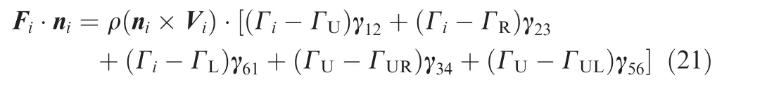
Each of the intensities of the vortex rings included in Eq.(21)can be written as the sum between the classic inviscid intensity and the correction factor,as presented in Eq.(9).In addition,the local velocity at the panel collocation point will be

By combining Eqs.(20),(9)and(22),the following expression is obtained for the normal force acting on each of the wing surface panels:

By introducing the normal force Figiven by Eq.(23)into the equality presented in Eq.(18),and by coupling theresulting equations with Eq.(12),a nonlinear system of 2N equations is obtained:

The unknown variables of the system are the N values of the intensity corrections of vortex rings and the N values of the surface transpiration velocities:

2.5.Nonlinear system analysis and solution
The nonlinear system of equations can be solved using Newton's method.43Starting with an initial guess of the solution vector X0,the quality of this estimate can be improved using the following iterative procedure:

In Eq.(26),J(Xk)is the Jacobian matrix of first-order partial derivatives calculated with the current estimate of the solution vector,-R(Xk)the system residual calculated with the current estimate of the solution vector,ΔX the solution increment and Ω an under-relaxation factor.The iterative solution procedure continues until the magnitude of the largest residual becomes smaller than the desired convergence criteria.
Starting from the expression of the nonlinear system in Eq.(24),the Jacobian matrix can be computed in four partitions as presented in Eq.(27).analysis,and the n the values can be interpolated for the current panel i,...as a function of the strip l on which the panel is placed,and of the relative chord-wise position of the panel collocation point with reference to the local airfoil chord.The derivative of the strip angle of attack can be determined based on Eq.(14)and is equal to

Here cs,lis the unit vector in the direction of the chord,ns,lis the unit vector in the direction normal to the chord,both vectors being in the plane of the local airfoil of the lthstrip,and vlkis the velocity induced by the unit strength vortex ring k at the lthstrip collocation point.
The following notations have been introduced:


The derivatives of the normal force determined by Eq.(23)with respect to the intensity corrections of vortex rings can be obtained through mathematical operations.More attention will be given to the derivative of the viscous pressure coefficient difference.
These values are obtained following a two-dimensional strip analysis of the wing,where each strip airfoil was calculated under the corresponding local flow conditions.Assuming incompressible flow,the strip pressure coefficient distribution depends only on the local angle of attack given by Eq.(14).

The other three partitions of the Jacobian can be determined much faster than the first partition.The second partition is the NXN null matrix,the third partition is simply the matrix given by the linear VLM method,as determined in Eq.(8),while the last partition is the NXN identity matrix,giving the Jacobian matrix the form presented as follows:

It must be observed that the local value of the pressure coefficient difference between the lower and upper surfaces also depends on the chord-wise position where it is calculated.Thus,the derivative of the pressure coefficient difference can be written as follows:

where αlrepresents the lthstrip effective angle of attack.
Thefirst right hand side term of Eq.(28)can be estimated for each wing strip while performing the two-dimensional strip
2.6.Aerodynamic forces and moments
After the determination of the values of the vortex rings'corrections with the iterative Newton procedure described in Eq.(26),the aerodynamic forces for each panel on the wing surface can be computed with Eq.(19),in which the circulation values are updated to their final values according to Eq.(9).The total aerodynamic force is equal to the sum of the forces acting on each of the wing surface panels:

The total aerodynamic moment generated about a desired wing reference point,such as the quarter chord point of the wing root section,is given by the following expression,in which riis the position vector from the chosen wing reference point to the collocation point of the i wing panel:

The aerodynamic force given by Eq.(33)is calculated with respect to the wing-fixed reference system.To determine the wing lift CLand induced drag CDI,the obtained force is projected onto the wind-oriented reference system:

where αgis the global(geometric)angle of attack of the wing,while F(x)and F(z)are the components of the aerodynamic force on the respective axes of the wing-fixed system.Following the wing strip analysis performed as part of the solution procedure,the total wing profile drag CD0(also known as parasite drag)can be calculated based on the two-dimensional airfoil drag by direct integration:

In Eq.(36),S is the wing area,B the wingspan,Cd(y)the two-dimensional drag coefficient of the local airfoil section and c(y)the local chord of the wing.Finally,the total drag coefficient is given by the sum of the induced drag coefficient and the profile drag coefficient:

3.Nonlinear VLM validation for different test cases
3.1.Grid resolution convergence study
To verify the influence of the wing surface grid resolution on the converged values of the aerodynamic coefficients,a study was performed using four test wing geometries.The wings were generated using the NACA0012 airfoil and cover four different scenarios:low aspect ratio–low sweep angle,low aspect ratio–high sweep angle,high aspect ratio–low sweep angle and high aspect ratio–high sweep angle.Details on the geometries of the four test wings are presented in Table 1.
All four tests were performed using the same Newton iteration convergence criterion of 10-3imposed for the maximum residual value.Eight different surface grids of increasing mesh density were generated for each of the geometries,each grid having a constant spacing in both chord-wise and span-wise directions.The total number of cells for the wing semi-span generated for each of the eight grids,as well as the chord-wise number NXand span-wise number NYare presented in Table 2.

Table 1 Details of test wings used for grid convergence study.

Table 2 Number of cells included at each grid level used for convergence study.
In Fig.5,the variations of the lift coefficient,drag coefficient and pitching moment coefficient about the quarter chord point of the root chord are presented,for the four test wings,as a function of the grid refinement level.For a better visualization and in order to provide direct information on the aerodynamic coefficients' variation with the refinement level,all the coefficient values have been normalized using the value obtained for the finest grid,which is Grid 8.
The nonlinear VLM approach requires a sufficiently refined grid to achieve results that are grid-independent,as only for the seventh grid refinement level the results for all three aerodynamic coefficients and for all four wing geometries are within 1%of the values obtained with the most refined grid.
Fig.6 presents the convergence curves for different mesh refinement levels that were presented in Table 2.The first two grid levels did not achieve the desired convergence error of 10-3,and thus only Grid 2 is presented,because it obtained better results.For Grids 7 and 8,the convergence curves are almost superposed,and only Grid 7 is chosen for display to provide better visualization.The nonlinear algorithm reaches convergence in five or six iterations and the minimum residual value varies with the refinement level,achieving lower values on the finer meshes.
3.2.Verification of linear results with theoretical data
For the first verification case,the inviscid numerical results obtained with the new code are compared with the theoretical results for a two-dimensional flat plate section.44To achieve the desired two-dimensional flow conditions,a wing model of very high aspect ratio is constructed,with no taper,sweep,dihedral or twisting,and the results are plotted for its symmetry section.
The model has a wing span of 20 m and a chord of 1 m,and it is analyzed at an angle of attack of 10°and an airspeed of 10 m/s.
Fig.7 presents a comparison between the numericallyobtained pressure coefficient difference ΔCpvalues for the model symmetry section and the values predicted by twodimensional linear potential theory for the given flow conditions.It can be seen that a very good agreement exists between the two sets of results.
The second validation test is performed on the Warren 12 wing,a geometry that is classically used to verify the accuracy of vortex lattice codes.45The Warren 12 wing has a low aspect ratio,high sweep angle,flat surface geometry and its characteristics are presented in Table 3.

Fig.5 Convergence of aerodynamic coefficients with grid refinement level.
Table 4 shows the theoretical and numerical lift and pitching moment coefficients derivatives with the angle of attack.For the reference results presented,the lift and pitching moment coefficients are calculated using the average geometrical chord(instead mean aerodynamic chord that is often used),and the pitching moment coefficient is calculated about the root chord leading edge point.The VLM results are obtained using a wing surface mesh of 10 chord-wise panels and 15 span-wise panels per semi-span.The results are very good,with an error of 0.51%for the lift coefficient derivative with α and 0.32%for the pitching moment coefficient derivative with α.

Fig.6 Residual convergence curves with grid refinement level.

Fig.7 Pressure coefficient variation for a flat plate,compared to exact linear potential theory.

Table 3 Geometry details for Warren 12 test wing.

Table 4 Comparison of lift and pitching moment coefficients' derivative with the angle of attack.
3.3.Validation of nonlinear results with experimental data
The first viscous flow validation test performed using the nonlinear VLM is done using geometrical and experimental datataken from the NACA Technical Note 1270.46The wing geometry chosen is a high aspect ratio shape with no sweep and a relatively high taper ratio.This wing is constructed using airfoils from the NACA 44-series,with the root section airfoil being a NACA 4422 and the tip section airfoil a NACA 4412.Table 5 presents details about the geometry of the test wing model.

Table 5 Geometric characteristics of NACA TN 1270 test wing.

Fig.8 Numerical versus experimental lift coefficient variations with the angle of attack for NACA TN 1270 wing.
The experimental results were obtained using the NACA variable density subsonic wind tunnel,for an airspeed of 65 m/s and a Reynolds number equal to 4X10⁶,as calculated with the mean aerodynamic chord value.For the numerical calculations,a mesh of 18 chordwise panels and 35 spanwise panels per wing semi-span is used.The solution of the nonlinear system is obtained with a convergence criterion of 10-3imposed for the maximum residual value.For low values of the angle of attack,the solution procedure requires no under-relaxation,but for the flight conditions close to stall,an under-relaxation factor of 0.75 is used to ensure the convergence of the solution.
In Figs.8–10,the results expressed in terms of wing lift coefficient,drag coefficient and quarter chord pitching moment coefficient are compared with the experimental data.The calculations are performed with both the well-known XFLR5 code and the newly proposed non-linear coupled algorithm.

Fig.9 Numerical versus experimental drag coefficient variations with the lift coefficient for NACA TN 1270 wing.

Fig.10 Numerical versus experimental pitching moment coefficient variations with the lift coefficient for the NACA TN 1270 wing.
The nonlinear VLM code produces an accurate estimation of the viscous lift coefficient slope,and it slightly overestimates the stall angle(16°in the numerical results versus 14.8°in the experiment)and the maximum lift coefficient value(1.425 in the numerical results versus 1.340 in the experiment).With XFLR5's viscous lifting line model,a very good estimation of the lift curve slope is obtained,but the maximum CLvalue and the stall angle are significantly over-estimated.
The drag coefficient estimation is very accurate for the lift coefficient range below 0.6,after which the numerical code tends to underestimate the drag coefficient values,but it still captures the steep increase associated with stall progression over the wing surface.
XFLR5's drag prediction accuracy is equally good,except for the very high lift conditions,where the over-predicted stall angle results in under-predicted drag coefficient values.
Concerning the pitching moment coefficient,the numerical nonlinear VLM results are in closer agreement with the experimental ones,capturing both the linear variation and predicting the nonlinear behavior characteristic of the higher angles of attack cases.An underestimation of the pitching moment value can be observed for the higher lift coefficient conditions,but the quality of the results is good.
The second validation test performed using the nonlinear VLM is done using geometrical and experimental data taken from the NACA Technical Note 1208.47The wing geometry features a high aspect ratio and a high sweep back angle.The model is constructed using a NACA 6-series airfoil section constant along the wingspan.The geometrical characteristics of the test wing are presented in Table 6.
As in the previous validation case,the experimental results were obtained in the NACA variable density subsonic wind tunnel,for an airspeed of 65 m/s and a Reynolds number of 4X10⁶.The numerical results are obtained using a mesh of 18 chordwise panels and 35 spanwise panels per wing semispan and the convergence criterion of 10-3imposed for the maximum residual value.
In Figs.11 and 12,the results for the wing lift coefficient and quarter chord pitching moment coefficient variations are compared with the experimental data.Drag coefficient data is not provided in Ref.47 to allow for a comparison.
The viscous lift coefficient slope predicted by the nonlinear VLM is slightly higher than the experimental value,with a lift overestimation for angles of attack higher than 10°.There is an underestimation of the stall angle(21°for the experiment,versus 19.5°in the numerical results),but a very good agreement exists for the maximum lift coefficient(1.01 for the experiment,versus 1.04 in the numerical results).XFLR5 accurately predicts the lift curve slope,but it slightly overestimates the lift values for the entire analysis range.Results could not be obtained for angles of attack higher than 18°due to convergence problems,but again the maximum CLvalue is not accurately predicted.

Table 6 Geometric characteristics of NACA TN 1208 test wing.

Fig.11 Numerical versus experimental lift coefficient variations with the angle of attack for the NACA TN 1208 wing.

Fig.12 Numerical versus experimental pitching moment coefficient variations with the lift coefficient for the NACA TN 1208 wing.
The linear variation of the pitching moment coefficient is very well captured,but there are some differences for the nonlinear higher lift conditions,where the swept back wing experiences an early tip stall phenomenon.As this behavior is difficult to accurately capture,it is responsible for the numerical over-prediction of both pitching moment and lift coefficients.However,there is an important quality improvement over the XFLR5 code,especially concerning the high angle of attack characteristics of the high-sweep wing.
In addition to the variations of lift and pitching moment coefficients and their numerical versus experimental comparisons,the span-wise wing loading is validated with the wind tunnel experimental data.47The comparison is performed at an angle of attack of 4.7°and is presented in Fig.13.

Fig.13 Comparison of span-wise loading for NACA TN 1208 wing at 4.7°angle of attack.
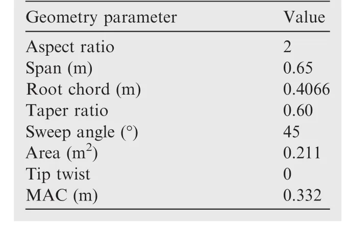
Table 7 Geometric characteristics of NACA RM L50F16 test wing.
The third viscous flow validation test performed using the nonlinear VLM is done using geometrical and experimental datataken from the NACA Research Memorandum L50F16.48The wing geometry chosen is a very low aspect ratio shape with high sweep angle.This wing is constructed using the NACA 65A006 airfoil.Table 7 presents details on the geometry of the test wing model.
The experimental results were obtained in the NACA variable density subsonic wind tunnel,for an airspeed of 35 m/s and a Reynolds number equal to 6X10⁶,as calculated with the mean aerodynamic chord value.For the numerical calculations,a mesh of 18 chordwise panels and 35 spanwise panels per wing semi-span is used.The solution of the nonlinear system is obtained with a convergence criterion of 10-2imposed for the maximum residual value.
In Figs.14 and 15,the wing lift coefficient,drag coefficient and quarter chord pitching moment coefficient obtained numerically with the new proposed non-linear VLM and the XFLR5 code are compared with the experimental data.
A very good prediction of the lift coefficient exists for angles of attack smaller than 10°.When the angle of attack increases above this value,the lift values predicted by the nonlinear code are smaller than the experimental ones.XFLR5 obtains a slightly better estimation of the lift coefficient for angles of attack higher than 10°,but an under-prediction still exists.Neither of numerical codes can obtain converged results for angles of attack higher than 20°,and thus the maximum lift coefficient and the stall angle are not captured in these numerical results.

Fig.14 Numerical versus experimental lift coefficient variations with angle of attack for NACA RM L50F16 wing.

Fig.15 Numerical versus experimental drag coefficient and pitching moment coefficient variations with lift coefficient for NACA RM L50F16 wing.
Concerning the drag coefficient estimation,there is a very good match between the nonlinear VLM results and the experimental data,especially for lift coefficient values smaller than 0.4,but the overall quality of the numerical results remains good for the entire analysis range.XFLR5's drag prediction accuracy is equally good for the lower lift range,and an under-estimation is observed for lift coefficient values higher than 0.4.
The pitching moment coefficient results obtained by the non-linear VLM code are good for the test cases in which the lift coefficient is smaller than 0.3.For the rest of the analysis range,the non-linear moment variation is captured by the numerical results,but the predicted values are much smaller than the experimental measurements.The XFLR5 results are also good for CLsmaller than 0.3,but the moment variation remains linear for the entire range,a behavior characteristic to the classic VLM models.
For all the validation results presented,the strip airfoil aerodynamic characteristics are calculated during the program execution with the Xfoil solver.It must be noted that the quality of the three-dimensional results is significantly influenced by the quality of the two-dimensional airfoil calculations,due to the very strong coupling between the 2D strip results and the 3D non-linear mathematical model,coupling that constitutes the base for constructing the non-linear mathematical model.This observation is especially true for the higher angles of attack,where the Xfoil solver precision is significantly influenced by the airfoil characteristics(camber distribution,thickness values)and by the Reynolds number value.The use of a two-dimensional flow solver is preferred to the use of experimentally-determined airfoil performance databases because of the plan to utilize the code to perform wing optimizations and morphing wing analysis that would also include modifications of the airfoil shape.
4.Application to wing design and optimization
4.1.Redesign of Hydra Technologies S4 UAS Wing
The nonlinear Vortex Lattice Method described above could be used at the early design phases of subsonic aircraft lifting surfaces,as it provides sufficiently accurate estimations of viscous aerodynamic characteristics for only a fraction of the computational requirements are needed to perform a three dimensional CFD calculation.On a typical desktop workstation,the execution time of the code is only around 1%of the equivalent CFD solution time.When the strip airfoil analyses are performed during execution,the n a much greater amount of time is devoted to that task than the amount of time needed to calculate the Jacobian matrix and solve the linear system.Thus,the calculation times can be significantly further reduced by performing the strip calculations in parallel mode,or by using airfoil experimental performance databases instead of running the two-dimensional solver.
In addition to its application to wing design,the method could also be integrated in optimization routines aimed at improving one or several of a wing's geometrical characteristics and aerodynamic coefficients,since the rapid execution time compensates for the high number of evaluations usually associated with optimization procedures.
A redesign of the Hydra Technologies S4 Unmanned Aerial System(UAS)wing is performed using the nonlinear VLM solver coupled with an optimization routine based on the Artificial Bee Colony algorithm.24,25This UAS is designed andbuilt in Mexico,and serves as an aerial surveillance system,for both military and civilian missions.The geometrical characteristics of the UAS-S4 wing are presented in Table 8.

Table 8 Geometrical characteristics of UAS-S4 wing.
The wing redesign is performed by means of an optimization aimed at improving the wing lift-to-drag ratio L/D over a rage of angle of attack values.The optimization procedure focuses only on aerodynamic performance,and so no structural or weight aspects are considered.The analyses are performed at an airspeed of 50 m/s,with a Reynolds number of 2.13X10⁶,as calculated with the mean aerodynamic chord.
The wing shape modification is performed by specifying the wing span,taper ratio and sweep angle as optimization variables.In addition to a redesign focused only on the geometrical parameters' changes,a modification of the wing airfoil is also performed in a second optimization procedure.The airfoil curve is parameterized using Non-Uniform Rational B-Splines (NURBS),and the coordinates of four NURBS control points situated on the airfoil upper surface are added to the optimization variables.Other possible techniques are the CIRCLE method49or the radial basis function method.50The airfoil shape change can be achieved by the upper skin morphing concept detailed in Refs.24,25,27,28.

Fig.16 Comparison between original and redesigned wing and airfoil shapes.

Table 9 Comparison of aerodynamic coefficients generated by UAS-S4 original and two redesigned wings,for all of analyzed flight conditions.
Fig.16 presents a comparison between the original and redesigned wing shapes,as well as between the original and redesigned airfoil.The detailed values of the aerodynamic coefficients for the original wing,the redesigned wing with shape modification and the redesigned wing with both shape and airfoil modifications are presented in Table 9.
In Fig.17,a comparison is presented between the lift coefficient CLvariations with the angle of attack,the drag coefficients' variations with the lift coefficient(the total drag coefficient CD,the induced drag coefficient CDIand the profile drag coefficient CD0)for the original wing,the optimized wing with redesigned geometrical shape and the optimized wing with redesigned geometrical shape and airfoil.
As expected,the higher aspect ratio,lower sweep redesigned wing provides a higher lift coefficient than the original design at any given angle of attack value in the chosen design range.Concerning the induced drag,significant reductions are obtained,with an average reduction value of 20%.The wing with the redesigned geometry develops higher profile drag coefficient values compared to the baseline wing,the increase being as high as 6%for the 4°angle of attack flight condition.However,this performance loss observed in the profile drag variation does not cancel out the improvements gained in induced drag.Thus,the redesigned wing generates a smaller total drag coefficient for the entire design range,with drag reductions of up to 10%,allowing to obtain a higher lift-todrag ratio and therefore a higher aerodynamic efficiency for the UAS-S4 during surveillance flights.
The second optimization procedure,in which the baseline airfoil is also modified in addition to the wing plan-form shape,is performed with the goal of eliminating the profile drag increase that is observed in the first redesign procedure.Because of the fact that the wing profile drag represents the spanwise integration of the 2D drag generated by the wing cross-sections,its value can be modified by changing the wing airfoil shape.
The obtained results show that the optimized wing airfoil shape provides a better performance in terms of profile drag,with the maximum reduction of 7.62%over the baseline design being obtained for an angle of attack of 0°.This reduction becomes smaller as the angle of attack increases or decreases.However,after the comparison of the profile drag coefficient values calculated for the two redesigned wings(the wing with only geometrical change and the wing with both geometrical change and airfoil optimization),it can be observed that profile drag increase mentioned above is effectively eliminated.Thus,by modifying the wing airfoil in addition to its planform shape,further drag coefficient reductions between 1%and 4.5%are obtained.

Fig.17 Comparison between lift and drag coefficients for original and redesigned wings.

Table 10 Geometric characteristics of CRIAQ MDO 505 wing.
4.2.Analysis of CRIAQ MDO 505 project morphing wing
The wing model used in the MDO 505 project was designed to be representative of a real regional aircraft wing tip,and thus all its dimensions were designed according to this objective.The geometrical characteristics of the wing model are presented in Table 10.The wing model was equipped with a flexible upper surface whose shape could be modified,as function of the flight condition,using four electrical actuators placed inside the wing box and arranged in two spanwise actuation lines.The flexible skin extended between 20%and 65%of the wing chord,over the entire span of the model.
Aerodynamic optimizations were performed to determine the displacements of the electrical actuators required to improve the performance of the morphing wing with reference to the original wing.The optimizations were performed with the objective of delaying the laminar-to-turbulent transition location on the upper surface,and thus to achieve drag coefficient reductions through the reduction of the wall friction stress.
In order to reduce the execution computing times as much as possible,the aerodynamic optimizations were performed under the two-dimensional flow assumption using Xfoil and a genetic algorithm optimizer,but for the local flow conditions(Reynolds number,effective angle of attack)corresponding to the mean aerodynamic chord of the model.51
The two-dimensional optimization provided good results,because of the fact that upper surface transition location delay of up to 4%of the chord and airfoil drag coefficient reductions of up to 4%were obtained.It must be noted that the aerodynamic optimization procedure was performed under all constraints imposed by the actual behavior of the model structure and by the technical limitations of the flexible composite-material upper skin.

Table 11 Comparison of aerodynamic coefficients generated by MDO 505 project original and morphed wings,for all of analyzed flight conditions.
To verify the impact of the two-dimensional optimizations on the overall three-dimensional wing model performance,the morphing wing geometry is analyzed in 3D using the nonlinear VLM model.A total of nine flight conditions are considered,all of the m at a Mach number of 0.15 and a flow Reynolds number of 4.57X10⁶.For each case,the geometry of the wing is constructed using the original airfoil for the root and tip sections,and the corresponding morphed airfoil shapes for the two spanwise sections where the electrical actuators are placed.
Table 11 presents the values of the aerodynamic coefficients for the original wing and for the morphed wing.Reductions of the profile drag coefficient of up to 3%are obtained by morphing the wing upper surface,thus verifying the accuracy of the two-dimensional optimizations.Compared to the baseline design,the optimized wing generates lift coefficient values smaller with 0.10%–0.30%,but it also achieves a reduction of the induced drag coefficient,the reduction percentage being between 0.60%and 3%.The total drag coefficient reductions obtained by the morphing wing compared to the original design are between 0.70%and 3%.
Due to its very low aspect ratio,the wing model gives a poor performance concerning the induced drag,whose contribution to the total drag is higher than for a regular,high aspect ratio transport aircraft wing.Because of the fact that the upper skin morphing concept is designed to reduce the friction drag coefficient by delaying the laminar-to-turbulent transition location,its efficiency is reduced when applied to a low aspect ratio wing.However,for a typical wing of high aspect ratio,such as the UAS-S4 wing analyzed in the previous section,the flexible upper skin could prove to be effective in providing significant total drag reductions.
In Fig.18,a comparison is presented between the lift coefficient CLvariations with the angle of attack,the drag coefficients' variations with the lift coefficient(the total drag coefficient CD,the induced drag coefficient CDIand the profile drag coefficient CD0)for the original and morphed wings.
5.Conclusions
The starting point for the non-linear VLM equations was the inviscid non-planar formulation of the classical VLM.The intensities of the vortex rings were modified by the introduction of a correction term.Viscous aerodynamic forces were calculated by analyzing the wing strips with a two-dimensional flow solver and by interpolating the results on the wing surface mesh.The non-linear equations allowing the calculation of the correction terms were constructed by making the inviscid pressure coefficient difference equal to the determined viscous pressure coefficient difference,and the n the non-linear system was solved using Newton's classic method.
Convergence studies were performed on several different test wings and have shown that the non-linear VLM method required a sufficiently refined mesh in order to achieve meshindependent results.Validations of the obtained results were performed using wing performance experimental data available in the literature.Good results were obtained in the estimation of the aerodynamic coefficients for both low and high sweep wings.Lift coefficient and pitching moment coefficient curve derivatives were very well predicted,as well as an accurate estimation of the drag coefficient.The results could be improved further by using experimental performance databases for the strip airfoil calculations,as there is a strong coupling with the quality of the two-dimensional calculations.
The non-linear VLM method was applied for a classic wing redesign problem on the Hydra Technologies S4 UAS.For flight conditions typical of cruise and surveillance flights,the lower sweep and higher aspect ratio wing obtained following the shape optimization provided better lift to drag ratios,as expected.A second optimization was performed,in which the wing airfoil shape was added to the optimization variables.Very good results were obtained,with further drag reductions of up to 5%obtained over the simple redesigned wing.
Another application of the code was the calculation of the aerodynamic performance gains obtained through upper surface morphing for a low aspect ratio wing model based on the wing tip of a real regional aircraft.The optimizations were performed in two-dimensions and took into consideration all the constraints imposed by the structure.The morphing wing has the potential to reduce the viscous drag coefficient by up to 3%over the baseline design.

Fig.18 Comparison between lift and drag coefficients for original and morphed wings.
Acknowledgments
We would like to thank the Hydra Technologies Team in Mexico for their continuous support,and especially Mr.Carlos Ruiz,Mr.Eduardo Yakin and Mr.Alvaro Gutierrez Prado.We would also like to thank the Natural Sciences and Engineering Research Council of Canada (NSERC) for the funding of the Canada Research Chair in Aircraft Modeling and Simulation Technologies.In addition we would also like to thank the Canada Foundation of Innovation (CFI),the Ministe`re du De´veloppement e´conomique,de l'Innovation et de l'Exportation (MDEIE) and Hydra Technologies for the acquisition of the UAS-S4 using the Leaders Opportunity Funds.
We would like to indicate our appreciation for the financial support obtained in the framework of the CRIAQ MDO-505 project and for the implication of our industrial partners Bombardier Aerospace and Thales Canada.We also wish to thank NSERC for their support.Special thanks are dues to our collaborators and leaders in this project:Mr.Patrick Germain and Mr.Fassi Kafyeke from Bombardier Aerospace,Mr.Philippe Molaret from Thale`s Canada and Mr.Eric Laurendeau from E´cole Polytechnique.
1.International Civil Aviation Organisation (ICAO).Aviation's contribution to climate change.Environmental Report;2010.Available from:http://www.icao.int/.
2.Sofla AYN,Meguid SA,Tan KT,Yeo WK.Shape morphing of aircraft wings:Status and challenges.Mater Des2010;31(3):1284–92.
3.Stanewsky E.Adaptive wing and flow control technology.Progr Aerospace Sci 2001;37:583–667.
4.Barbarino S,Bilgen O,Ajaj RM,Friswell MI,Inman DJ.A review of morphing aircraft.J Intell Mater Syst Struct 2011;22(9):823–77.
5.Gamboa P,Alexio P,Vale J,Lau F,Suleman A.Design and testing of a morphing wing for an experimental UAV.Neuilly-sur-Seine,France;2007.Report No.:RTO-MP-AVT-146.
6.do Vale J,Leite A,Lau F,Suleman A.Aero-structural optimization and performance evaluation of a morphing wing with variable span and camber.J Intell Mater Syst Struct 2011;22(10):1057–73.
7.Falcao L,Gomes AA,Suleman A.Aero-structural design optimization of a morphing wingtip.J Intell Mater Syst Struct 2011;22(10):1113–24.
8.Pecora R,Barbarino S,Concilio A,Lecce L,Russo S.Design and functional test of a morphing high-lift device for a regional aircraft.J Intell Mater Syst Struct 2011;22(10):1005–23.
9.Diodati G,Concilio A,Ricci S,de Gaspari A,Liauzun C,Godard JL.Estimated performance of an adaptive trailing-edge device aimed at reducing fuel consumption on a medium-size aircraft.Proceedings of SPIE 8690,industrial and commercial applications of smart structures technologies;2013 March 10–14;San Diego,CA;2013.p.86900E1-16.http://dx.doi.org/10.1117/12.2013685.
10.Pecora R,Amoroso R,Amendola G,Concilio A.Validation of a smart structural concept for wing-flap camber morphing.Smart Struct Syst 2014;14(4):659–78.
11.Pecora R,Amoroso F,Lecce L.Effectiveness of wing twist morphing in roll control.J Aircraft 2012;49(6):1666–74.
12.Botez RM,Molaret P,Laurendeau E.Laminar flow control on a research wing:project presentation covering a three-year period.In:Canadian aeronautics and space institute annual general meeting;2007.p.1–8.
13.Brailovski V,Terriault P,Coutu D,Georges T,Morellon E,Fischer C,et al.Morphing laminar wing with flexible extrados powered by shape memory alloy actuators.Proceedings of SMASIS08 ASME conference on smart materials,adaptive structures and intelligent systems,2008 October 28–30.Ellicott City,Maryland,USA;2008.p.1–9.
14.Pages L,Trifu O,Paraschivoiu I.Optimized laminar flow control on an airfoil using the adaptable wall technique.Proceedings of the Canadian aeronautics and space institute annual general meeting;2007.
15.Popov AV,Grigorie TL,Botez RM,Mamou M,Mebarki Y.Modeling and testing of a morphing wing in an open loop architecture.J Aircraft 2010;47(3):917–23.
16.Grigorie TL,Popov AV,Botez RM.Adaptive neuro-fuzzy controllers for an open loop morphing wing system.Proc Inst Mech Eng,Part G:J Aerospace Eng 2009;223(7):965–75.
17.Popov AV,Grigorie TL,Botez RM,Mamou M,Mebarki Y.Real time airfoil optimisation of a morphing wing in a wind tunnel.J Aircraft 2010;47(4):1346–54.
18.Popov AV,Grigorie TL,Botez RM,Mamou M,Mebarki Y.Closed loop control of a morphing wing in a wind tunnel.J Aircraft 2010;47(4):1309–17.
19.Grigorie TL,Popov AV,Botez RM,Mamou M,Mebarki Y.Onoff and proportional-integral controller for morphing wing.Part 1:Actuation mechanism and control design.Proc Inst Mech Eng,Part G:J Aerospace Eng 2012;226(2):131–45.
20.Grigorie TL,Popov AV,Botez RM,Mamou M,Mebarki Y.Onoff and proportional-integral controller for morphing wing.Part 2:Control validation,numerical simulations and experimental tests.Proc Inst Mech Eng,Part G:J Aerospace Eng 2012;226(2):146–62.
21.Sainmont C,Paraschivoiu I,Coutu D,Brailovski V,Laurendeau E,Mamou M,et al.Boundary layer behaviour on a morphing wing:simulation and wind tunnel tests.In:Canadian aeronautics and space institute aero09 conference;2009.
22.Grigorie TL,Botez RM,Popov AV.Design and experimental validation of a control system for a morphing wing.AIAA atmospheric flight mechanics conference;Minneapolis,USA;2012 August 13–16.2012.p.1–11.
23.Sugar Gabor O,Koreanschi A.Low-speed aerodynamic characteristics improvement of ATR 42 airfoil using a morphing wing approach.IECON 2012,38th annual conference of IEEE industrial electronics,aircraft systems modeling section;2012 October 25–28;Montreal,Canada.Reston:IEEE Press,2012.p.5451–6.
24.Sugar Gabor O,Simon A,Koreanschi A,Botez AM.Numerical optimization of the S4 E´hecatl UAS airfoil using a morphing wing approach.In:American Institute of Aeronautics and Astronautics 32nd applied aerodynamics conference;2013 June 16–20;Atlanta,GA,USA.2014.
25.Sugar Gabor O,Simon A,Koreanschi A,Botez RM.Application ofa morphing wing technology on Hydra Technologies Unmanned Aerial System UAS-S4.In:ASME international mechanical engineering congress and exposition IMECE14;2014 November 14–20;Montreal,Canada.2014.
26.Sugar Gabor O,Koreanschi A,Botez RM.An efficient numerical lifting line method for practical wing optimization through morphing.In:Canadian aeronautics and space institute CASI AERO13 conference;2013 April 30–May 2;Toronto,Canada.2013.
27.Sugar Gabor O,Koreanschi A,Botez RM.Optimization of an unmanned aerial systems' wing using a flexible skin morphing wing.SAE Int J Aerospace 2013;6:115–21.
28.Sugar Gabor O,Koreanschi A,Botez RM.Numerical study of UAS-S4 E´hecatl aerodynamic performance improvement using a morphing wing technology.Unmanned systems Canada 2014 annual conference;2014 November 4–6;Montreal,Canada.2014.
29.Lingard JS.Ram-air parachute design.13th AIAA aerodynamic decelerator systems technology conference;Clearwater Beach,USA.1995.
30.Hedman SG.Vortex lattice method for calculation of quasi steady state loadings on thin elastic wings in subsonic flow.Stockholm:Aeronautical Research Institute of Sweden;1966.Report No.:FFA report 105.
31.Katz J,Plotkin A.Low speed aerodynamics:from wing theory to panel methods.New York:McGraw-Hill Inc;1991.p.389–401.
32.Murua J,Palacios R,Graham JMR.Applications of the unsteady vortex-lattice method in aircraft elasticity and flight dynamics.Progr Aerospace Sci 2012;55:46–72.
33.Leifsson L,Slawomir K,Bekasiewicz A.Fast low- fidelity wing aerodynamics model for surrogate-based shape optimization.Proc Comput Sci 2014;29:811–20.
34.Smith DD,Ajaj RM,Isikveren AT,Friswell MI.Multi-objective optimization for the multiphase design of active polymorphic wings.J Aircraft 2012;49(5):1153–60.
35.Hu TY,Yu XQ.Aerodynamic/stealthy/structural multidisciplinary design optimization of unmanned combat air vehicle.Chin J Aeronautics 2009;22(4):380–6.
36.Li PF,Zhang BQ,Chen YC,Yuan CS,Lin Y.Aerodynamic design methodology for blended wing body transport.Chin J Aeronautics 2012;25(4):508–16.
37.Xie C,Wang L,Yang C,Liu Y.Static aeroelastic analysis of very flexible wings based on non-planar vortex lattice method.Chin J Aeronautics 2013;26(3):514–21.
38.Phillips W,Snyder D.Modern adaptation of Prandtl's classic lifting line theory.J Aircraft 2000;37(4):662–70.
39.Drela M.XFOIL:an analysis and design system for low Reynolds number airfoils.Low Reynolds number aerodynamics.Berlin:Springer;1989.p.1–12.
40.Mariens J,Elham A,van Tooren MJL.Quasi-three-dimensional aerodynamic solver for multidisciplinary design optimization of lifting surfaces.J Aircraft 2014;51(2):547–58.
41.Elham A.Adjoint quasi-three-dimensional aerodynamic solver for multi-fidelity wing aerodynamic shape optimization.Aerospace Sci Technol 2015;41:241–6.
42.Saffman P.Vortex dynamics.Cambridge:Cambridge University Press;1992.
43.Deuflhard P.Newton methods for nonlinear problems:affine invariance and adaptive algorithms.Springer Series in Computational Mathe matics,vol.35.Berlin:Springer;2004.
44.McCormick BW.Aerodynamics,aeronautics and flight mechanics.New York:John Wileyamp;Sons Inc.;1995.
45.Surfaces-vortex lattice module,user manual.Great OWL Publishing Engineering Software;2009.
46.Neely RH,Bollech TV,Westrick GC,Graham RR.Experimental and calculated characteristics of several NACA 44-Series wings with aspect ratios of 8,10 and 12 and taper ratios of 2.5 and 3.5.Hampton:Langley Memorial Aeronautical Laboratory;1947.Report No.:NACA-TN-1270.
47.Schneider WC.A comparison of the spanwise loading calculated by various methods with experimental loadings obtained on a 45o sweptback wing of aspect ration 8,at a Reynolds number of 4.0X10⁶.Hampton:Langley Memorial Aeronautical Laboratory;1951.Report No.:NACA-TR-1208.
48.Cahill JF,Gottlieb SM.Low-speed aerodynamic characteristics of a series of swept wings having NACA 65A006 airfoil sections.Hampton:Langley Memorial Aeronautical Laboratory;1950.Report No.:NACA-RM-L9J20.
49.Korakianitis T,Rezaienia MA,Hamakhan I,Avital EJ,Williams JRR.Aerodynamic improvements of wind-turbine airfoil geometries with the prescribed surface curvature distribution(CIRCLE)blade design method.Trans ASME J Eng Gas Turbines Power 2012;134(8),082601-1-9.
50.Fincham JHS,Friswell MI.Aerodynamic optimization of a camber morphing aerofoil.Aerospace Sci Technol 2015;43:245–55.
51.Koreanschi A,Sugar Gabor O,Botez RM.New numerical study of boundary layer behaviour on a morphing wing-with-aileron system.32nd AIAA applied aerodynamics conference;2014 June 16–20;Atlanta,GA,USA.2014.p.1–18.
Oliviu Sugar GaborGraduated Bachelor(2009)and Master(2011)studies in aerospace engineering from Polytechnic University of Bucharest,and is currently a Ph.D.candidate at Ecole de Technologie Superieure,Montreal.His research interests include aerodynamics,CFD,optimization techniques and geometry parameterization.
Andreea KoreanschiReceived her Bachelor degree in 2009 and her Master degree in 2011,from the Polytechnic University of Bucharest,both in aerospace engineering.Currently is a Ph.D.candidate at Ecole de Technologie Superieure,Montreal.Her research interests are aerodynamics,adaptive aircraft structures,optimization and aeroelasticity.
Ruxandra Mihaela BotezFull Professor,Ph.D.,head of LARCASE laboratory and holder of the Canada Chair in Aircraft Modeling and Simulation Technologies.Her main research interests are aeroservoelasticity,active flight control,adaptive aircraft structures,aerodynamics,laminar flow technologies and aircraft modeling and simulation.
27 August 2015;revised 8 October 2015;accepted 8 March 2016
Available online 27 August 2016
Aerodynamic design;
Aerodynamic optimization;
Enhanced potential method;
Morphing wing;
Nonlinear vortex lattice
method;
Quasi-3D aerodynamic
method;
UAS optimization
©2016 Chinese Society of Aeronautics and Astronautics.Production and hosting by Elsevier Ltd.This is an open access article under the CC BY-NC-ND license(http://creativecommons.org/licenses/by-nc-nd/4.0/).
*Corresponding author.Tel.:+001 514 396 8560.
E-mailaddresses:oliviu.sugar-gabor.1@ens.etsmtl.ca (O.Sugar Gabor),andreea.koreanschi.1@ens.etsmtl.ca(A.Koreanschi),ruxandra.botez@etsmtl.ca(R.M.Botez).
Peer review under responsibility of Editorial Committee of CJA.
 CHINESE JOURNAL OF AERONAUTICS2016年5期
- CHINESE JOURNAL OF AERONAUTICS的其它文章
- Flapping wing micro-aerial-vehicle:Kinematics,membranes,and flapping mechanisms of ornithopter and insect flight
- Experimental study of flow field distribution over a generic cranked double delta wing
- Streamwise-body-force-model for rapid simulation combining internal and external flow fields
- An artificial neural network approach for aerodynamic performance retention in airframe noise reduction design of a 3D swept wing model
- effects of wing locations on wing rock induced by forebody vortices
- Turbulent boundary layer separation control using plasma actuator at Reynolds number 2000000