
A High-Performance W-Band Subharmonic Mixer Based on Anti-Parallel Diode Pair*
2016-12-23 07:26MINWenchaoSUNHaoZHANGQilianTONGRuiQIANRongSUNXiaowei
电子器件 2016年6期
MIN Wenchao,SUN Hao,ZHANG Qilian,TONG Rui,QIAN Rong,SUN Xiaowei*
(1.Shanghai Institute of Micro-System and Information Technology,Chinese Academy of Sciences,Shanghai 200050,China;2.University of Chinese Academy of Sciences,Beijing 100049,China)
A High-Performance W-Band Subharmonic Mixer Based on Anti-Parallel Diode Pair*
MIN Wenchao1,2,SUN Hao1,ZHANG Qilian1,TONG Rui1,QIAN Rong1,SUN Xiaowei1*
(1.Shanghai Institute of Micro-System and Information Technology,Chinese Academy of Sciences,Shanghai 200050,China;2.University of Chinese Academy of Sciences,Beijing 100049,China)
A high-performance W-band subharmonic mixer utilizing GaAs anti-parallel diode pair(APDP)is pre⁃sented.The APDP is fabricated by GaAs process platform of our laboratory,and the model of APDP shows ultrahigh cut-off frequency and low series resistance,which is suitable for W-band mixers.Based on the APDP,a W-band subharmonic mixer on quartz substrate was designed,fabricated and measured.The results show that the con⁃version loss of the subharmonic mixer is 9.2 dB~12 dB from 80 GHz to 100 GHz,and the required local oscillator(LO)power is just 6 dBm,which can significantly reduce the requirement for LO source.
subharmonic mixer;W-band;schottky diode;low LO power
Recently,radar and communication systems at W-band have been of an increasing importance[1-2].Mix⁃ers are widely used in transceiver/receiver(T/R)mod⁃ules,in which subharmonic mixers are the most popu⁃lar topology at millimeter-wave applications with its ad⁃vantages of subharmonically pumping,inherently sup⁃pressing local oscillator(LO)noise,and reducing the demands on LO source[3].Subharmonic mixers usually use a nonlinear device with an antisymmetric currentvoltage characteristic,such as anti-parallel diode pair(APDP).The subharmonic mixers already have been reported by adopting fineline structures[4],which is dif⁃ficult to be integrated with other planar circuits.There have also been several reports about subharmonic mix⁃ers of monolithic integrated circuit[5-7](MIC).Com⁃pared with MIC,hybrid integrated circuit(HIC)main⁃ tains the flexibility of design and fabrication[8],and it has lower cost.Moreover,by using the thin substrate,subharmonic mixers HIC has been smaller and small⁃er,which is in favor of small system integrations.
As the key component of mixers,the characteris⁃tics of APDP determine the performance of mixers,while APDP is significantly affected by its parasitic pa⁃rameters for millimeter-wave band[9-10].The model of APDP parasitic parameters[11-12]is adopted to analyze the characteristics of our APDP for its cut-off frequen⁃cy and series resistance.We designed and fabricated a W-band subharmonic mixer based on the APDP.The measured results show that the lowest conversion loss is 9.2 dB at 91 GHz,and the required LO power is as low as 6 dBm.Our mixer has the characteristics of sub⁃harmonically pumping and low LO power,which cansimplify LO source designs including oscillator,dou⁃bler and amplifier circuits.
1 Schottky Diode Model
The GaAs Schottky diode utilized in this paper is designed and fabricated in our laboratory.Fig.1(a)shows the photograph of the APDP with dot Schottky junction of 1μm diameter.By DC measurements,the main parameters of Schottky diode are that reverse saturation current Isis 4.62 fA,series resistance Rsis 12 Ω,and ideality factor n is 1.14.The classic equiva⁃lent model of APDP[12]is adopted to analyze the parasitic parameters as Fig.1(b)shows.
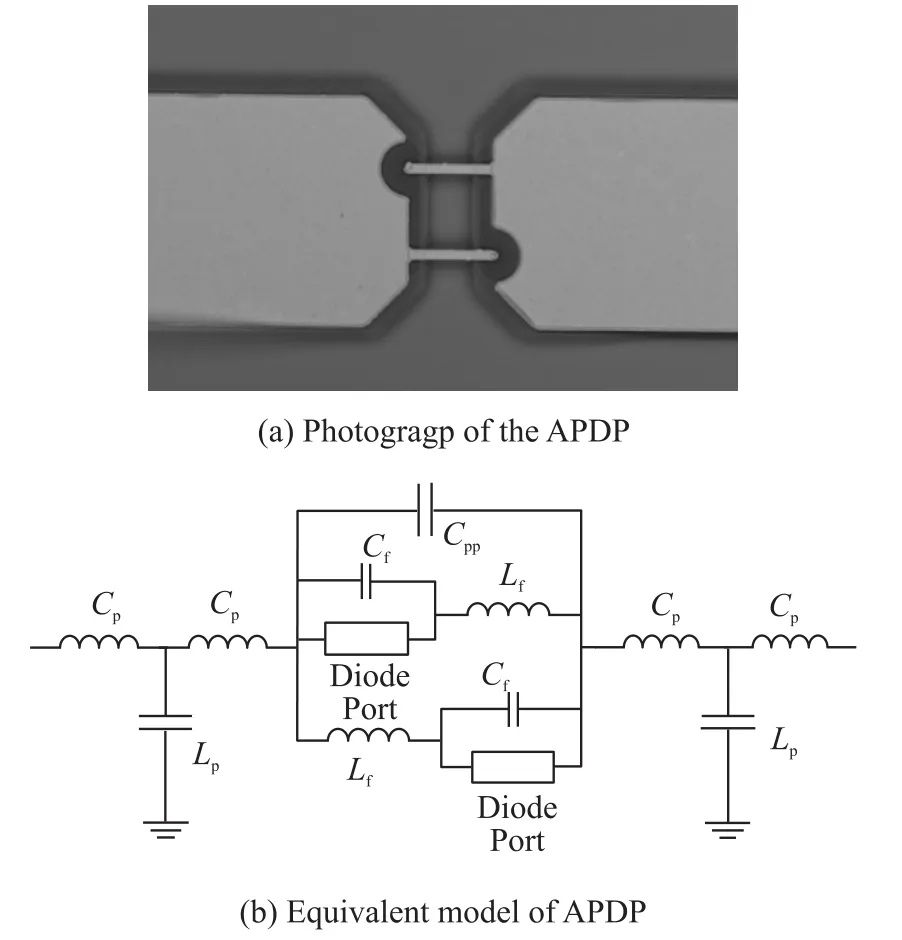
Fig.1 Photograph of APDF and its equivalent model
The S parameter measurements of APDP are im⁃plemented and compared with the APDP model above,and then we can get the zero-bias junction capacity Cj0of 2.5 fF and the parasitic parameters at Table 1.The model above reveals that the cut-off frequency of the APDP can be expressed as:
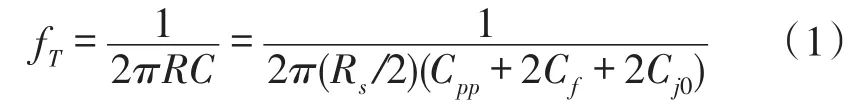
From Eq.(1),the cut-off frequency fTof our AP⁃DP can reach 1.3 THz,so it is suitable for W-band sub⁃harmonic mixer.Furthermore,the low serious resis⁃tance contributes to low conversion loss and LO power of the designed mixer below.
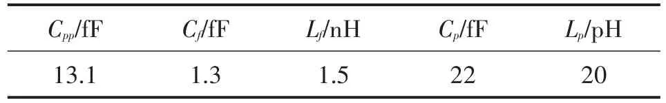
Table 1 Parasitic parameters of APDP model
2 Design of Subharmonic Mixer
The schematic of the subharmonic mixer circuit is shown in Fig.2(a).It consists of two networks,where RF network is on the left side of APDP,and LO net⁃work is on the right side.In the Radio Frequency(RF)network,RF port has a parallel-strip coupler to choke Intermediate Frequency(IF)signal,while IF port has a fan stub to choke RF signal,which are components of a duplexer for RF and IF signal.Meanwhile,a λLO/4 opencircuited stub provides the ground of LO signal.In the LO network,the 5nd stepped-impedance microstrip line is designed as a low pass filter(LPF),and its pass band is from DC to 50 GHz,which can feed LO signal to APDP.In addition,as the ground of RF signal,the LPF can reflect the RF signal to the APDP.The ground of IF signal is also designed with a fan stub of LO fre⁃quency.The schematic includes all of RF,LO and IF loops through APDP,which can achieve the subharmon⁃ic mixer.Finally,the both RF and LO network is simu⁃lated and optimized by ADS technology.By combining these networks with the analyzed APDP model,the sim⁃ulated result of conversion loss with a fixed IF frequen⁃cy(80 MHz)is shown in Fig.2(b).
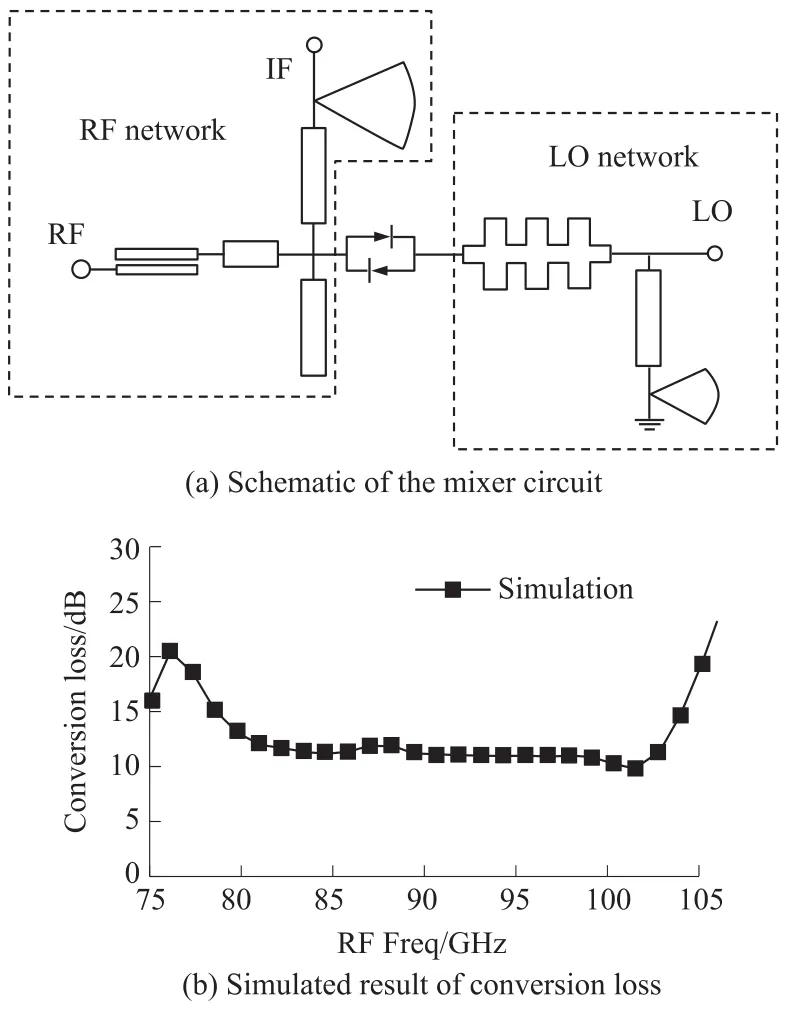
Fig.2 Mixer circuit and conversion loss
The mixer was fabricated on 0.127 mm thick quartz substrate and the APDP is flip-chip mounted shown in Fig.3.The ground-signal-ground(GSG)struc⁃tures with two fan stub capacitances are adopted atboth RF and LO ports in favor of feeding signals during on-chip test.Because of the low frequency of IF signal,it is difficult to design GSG structure for IF port,so that we adopted IF signal at a relatively low frequency,which can be extracted by DC probe during on-chip test.Meanwhile,the ground of IF signal is connected to the common ground by another DC probe.The mixer design can avoid via in the quartz substrate in favor of the simplification of fabrication process.Excluding the GSG pads for measurement,the actually chip area de⁃fined by the reference planes is 3.4 mm×2 mm.
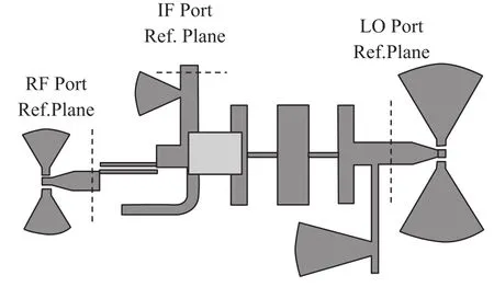
Fig.3 Photograph of the W-band subharmonic mixer
3 Measurements and Discussions
An on-chip measurement was implemented shown in Fig.4.RF and LO signal were fed by GSG probes. RF signal was supplied by Agilent N5245A network an⁃alyzer and a 75~110 GHz frequency extender in contin⁃uous wave mode,and calibrated at-20 dBm by power sensor,while LO signal was supplied by Agilent E8247C signal generator and a quadrupler.The extract⁃ed IF signal was linked to Agilent N9030A spectrum analyzer.All the loss of signal lines was calibrated and deembedded from the measured data,so the measured conversion loss represented the loss from the RF GSG pad to the IF-port reference plane(see Fig.3).In the actual application that the RF signal is fed on RF-port reference plane,the conversion loss can be further re⁃duced without RF GSG pad.
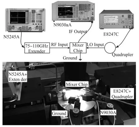
Fig.4 On-chip measurement for the mixer
RF frequency was set from 75 GHz to 105 GHz,while the IF frequency was fixed at 80 MHz.The mea⁃sured results are shown in Fig.5.The minimum conver⁃sion loss is 9.2 dB at 91 GHz of RF frequency.Fur⁃thermore,the mixer is broad-band with a conversion loss of 9.2 dB~12 dB from 80 GHz to 100 GHz.Dur⁃ing the measurement,we also set different LO power when the RF frequency was fixed at 90 GHz,and found that the optimum LO power is about 6 dBm.Al⁃though there is some difference of simulations and measurements which mainly results from the flip-chip mounting effect,the similar results and trends reveal that the APDP model is relatively exact for W-band applications.
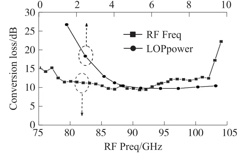
Fig.5 Measured conversion loss including CL(Coversion Loss)vs RF frequency and CL vs LO power
Compared with other W-band subharmonic mix⁃ers in Table 2,the mixer in this paper has a relatively good conversion loss,and furthermore the minimum LO power(6 dBm)and the widest band(80 GHz~100 GHz),which result from the high cut-off frequency and low series resistance of the APDP.
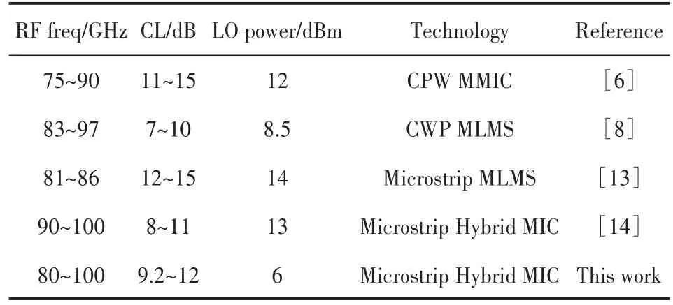
Table 2 Performances of the reported W-band subharmonic mixers
4 Conclusion
A W-band subharmonic mixer is designed and fab⁃ricated on quartz substrate utilizing our APDP,which is of flexible fabrication and low cost.According to ex⁃act APDP model,the APDP shows superior characteris⁃tics of high cutoff frequency fT and low series resis⁃tance Rs,which contribute to the high mixing perfor⁃mance in terms of the conversion loss and LO power. The results show that the conversion loss is 9.2 dB~12 dB from 80 GHz to100 GHz.Furthermore,the optimum LO power is 6 dBm,and this,to the best of our knowl⁃edge,is the minimum among the W-band subharmonic mixers of APDP technology.The subharmonic mixer with low LO power can reduce the demand on both the frequency and power of LO source.
[1]Pfeifer U R,Mishra C,Rassel R M,et al.Schottky Barrier Diode Circuits in Silicon for Future Millimeter-Wave and Terahertz Ap⁃plications[J].IEEE Trans Microw Theory Tech,2008,56(2):364-371.
[2]韩艳伟,汪海勇,高永安.W波段三倍频器的设计与仿真[J].电子器件,2012,35(5):509-513.
[3]Crowe T W,Mattauch R J.Analysis and Optimization of Millime⁃ter-and Submillimeter-Wavelength Mixer Diodes[J].IEEE Trans Microw Theory Tech,1987,35(2):159-168.
[4]Meier P J,Calviello J A,Bie P R.Wide-Band Subharmonically Pumped W-Band Mixer In Single-Ridge Fin-Line[J].IEEE Tran Microw Theory Tech,1982,23(12):2184-2189.
[5]Kanaya K,Kawakami K,Hisaka T,et al.A 94 GHz High Perfor⁃mance Quadruple Subharmonic Mixer MMIC[C]//IEEE MTT-S Int Microw Symp Dig,Seattle,MA,2002:1249-1252.
[6]Dyadyuk V,Archer J W,Stokes L.W-Band GaAs Schottky Diode MMIC Mixers for Multi-Gigabit Wireless Communications[C]//In Proc of 2nd Intern,Conf.on Wireless,Broadband and Ultra Wide⁃band Communications,Sydney,2007:27-30.
[7]Lin Chehung,Lai Yuann,Chiu Juichieh,et al.A 23-37 GHz Min⁃iature MMIC Subharmonic Mixer[J].IEEE Microw and Wireless Compon Lett,2007,17(9):179-181.
[8]Raman S,Rucky F,Rebeiz G M.A High-Performance W-band Uniplanar Subharmonic Mixer[J].IEEE Tran Microw Theory Tech,1997,45(6):955-962.
[9]Tang A Y,Stake J.Impact of Eddy Currents and Crowding Effects on High-Frequency Losses in Planar Schottky Diodes[J].IEEE Trans Electron Devices,2011,58(10):3260-3269.
[10]Tang A Y,Drakinskiy V,Yhland K,et al.Analytical Extraction of a Schottky Diode Model from Broadband S-Parameters[J].Tran Microw Theory Tech,2013,61(5):1870-1878.
[11]Kiuru T.Characterization and Modelling of THz Schottky Diodes[C]//39th International Conference on Infrared,Millimeter,and Terahertz waves,2014:1-3.
[12]Tang A Y,Bryllert T,Stake J.Geometry Optimization of THz Sub-Harmonic Schottky Mixer Diodes[C]//37th International Confer⁃ence on Infrared,Millimeter,and Terahertz Waves,2012:1-2.
[13]Stoneham E B.High-Precision Flip-Chip Process Yields E-band Harmonic Mixers With Potential Sub-10-dB Conversion Loss[C]//Proc of 36th European Microw Conf,Manchester,2006:506-509.
[14]Xu Zhengbin,Qian Cheng,Dou Wenbin,et al.Design of a W-band Sub-Harmonic Mixer by Employing Microstrip Technology[J].J Infrared Millim Waves,2013,32(3):242-247.
闵文超(1991-),男,江苏苏州人,汉族,中科院上海微系统与信息技术研究所,硕士研究生,研究方向为射频毫米波集成电路设计,minwc@mail.sim.ac.cn;

孙晓玮(1958-),女,陕西西安人,汉族,中科院上海微系统与信息技术研究所,研究员,博士研究生导师,研究方向为微波毫米波器件单片集成电路及其相关毫米波雷达探测器等,xwsun@mail.sim.ac.cn。
基于反向平行二极管对管的高性能W波段谐波混频器*
闵文超1,2,孙 浩1,张祁莲1,佟 瑞1,钱 蓉1,孙晓玮1*
(1.中国科学院上海微系统与信息技术研究所,上海200050;2.中国科学院大学,北京100049)
采用砷化镓反向平行二极管对管,提出了一款W波段高性能谐波混频器。二极管对管是由实验室砷化镓工艺线制作而成,并且二极管对管的模型显示具有极高的截止频率和低的串联电阻特性,所以适用于W波段。基于此二极管对管,设计、制作并测试了石英衬底上的W波段谐波混频器。结果显示在80 GHz~100 GHz的频率范围内,谐波混频器的变频损耗为9.2 dB~12 dB,并且所需要的本振功率仅为6 dBm,能够很好地减少对本振源的需求。
谐波混频器;W波段;肖特基二极管;低本振功率
TN454
A
1005-9490(2016)06-1283-04
2015-12-23 修改日期:2016-01-14

1250
10.3969/j.issn.1005-9490.2016.06.001
项目来源:上海市科委基础研究重大重点项目(14JC1407500)
猜你喜欢
文萃报·周五版(2021年19期)2021-08-05
数字通信世界(2020年5期)2020-06-15
科技传播(2019年23期)2020-01-18
新农业(2018年3期)2018-07-08
吉首大学学报(自然科学版)(2018年2期)2018-05-17
电子制作(2017年7期)2017-06-05
电子制作(2016年19期)2016-08-24
浙江大学学报(工学版)(2016年9期)2016-06-05
中学科技(2015年10期)2016-01-06
中国舰船研究(2015年2期)2015-02-10
