
Commercial Application of Novel Heavy Oil Catalytic Cracking Catalyst HSC
2017-05-09 15:37ZhangZhimin
中国炼油与石油化工 2017年1期
Zhang Zhimin
(Qilu Branch of SINOPEC Catalyst Co., LTD, Zibo 255336)
Commercial Application of Novel Heavy Oil Catalytic Cracking Catalyst HSC
Zhang Zhimin
(Qilu Branch of SINOPEC Catalyst Co., LTD, Zibo 255336)
The commercial application of a novel RFCC catalyst HSC used in an 1.4 Мt/a RFCC unit at a refnery A was introduced. The application results show that in comparison with the base catalyst, the yield of dry gas and slurry was reduced, while the total liquid yield, gasoline yield and LPG yield increased by 1.34, 5.05 and 1.43 percentage points, respectively. The properties of the products showed no signifcant change while the anti-abrasion strength of the catalyst was relatively high. Based on the mid-term calibration test, the summary calibration test and the daily statistics of long term industrial application practice, the HSC catalyst features a strong conversion ability of heavy oil, a high gasoline yield, a satisfactory product distribution and a good selectivity.
heavy oil, FCC catalyst, industrial application, structural stability
1 Introduction
FCC (fuid catalytic cracking) process, a major conversion process in petroleum refining, plays a key role at oil refineries and petrochemical plants. To many refineries, FCC unit is a crucial factor of gaining economic benefts and maintaining competitiveness in oil products market[1-2]. Processing of the FCC feedstock, which is getting increasingly heavy and inferior in recent years, needs a FCC catalyst that would have greater activity and hydrothermal stability to improve the ability of heavy oil conversion and resistance to heavy metal contamination. Therefore, the Y zeolite, which is a major active component in the FCC catalyst, is required to have high activity and structural stability. The catalyst needs to be ultra-stable and be rare-earth modifed to accomplish this goal[3-9]. The SINOPEC Research Institute of Petroleum Processing (RIPP) has developed a new production process for manufacture of high stability zeolite and prepared HSY zeolite with a relatively high activity and stability. On this basis, a novel RFCC catalyst HSC has been developed to contain the high stability zeolite HSY as its active component[10].
The feedstock of the 1.4 Мt/a RFCC unit at the refnery A is a mixture of Linshang crude and Shengli crude. To improve the heavy oil conversion ability of the unit, the product distribution, and the liquid yield of light hydrocarbons, the HSC catalyst produced by the Qilu Branch of SINOPEC Catalyst Company has been tested in the FCC unit of the refinery A since July 4, 2009. Furthermore, the industrial tests and long-term industrial application of the HSC catalyst also have been conducted. This article will present the industrial test results of RFCC catalyst HSC in the 1.4 Мt/a RFCC unit of the refnery A and the continuous industrial application of the catalyst launched by the end of 2015.
2 Design of HSC Catalyst and Its Main Performance
RIPP and the Qilu Branch of SINOPEC Catalyst Company have jointly developed the unit for production of highly stabilized zeolite HSY in commercial scale. By optimizing the parameters of the highly stabilized zeolite process technology and constantly improving the test unit, the continuous production of highly stabilized zeolite HSY has been successfully implemented. The highly stabilized zeolite HSY can satisfy the strict requirements for the FCC catalyst raised by the increasingly heavy FCC feedstock, because the zeolite HSY possesses asatisfactory performance in terms of high stability, high silica-alumina ratio, good thermal and hydrothermal stability and high ability of heavy oil conversion. With the newly developed highly stabilized zeolite HSY serving as its major active component, the RFCC gasolineenhancing catalyst HSC has advantages of high stability, thermal stability, gasoline selectivity and heavy oil cracking ability. To enhance the ability of large molecule cracking and metal resistance, a macroporous material is selected as the matrix coupled with adding metal-resistant components during its preparation. The HSC catalyst has been successfully produced by the Qilu Branch of SINOPEC Catalyst Company in commercial scale. The main properties of the fresh catalyst produced at the Qilu Branch of SINOPEC Catalyst Company are listed in Table 1.
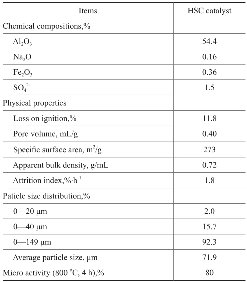
Table 1 The primary properties of HSC catalyst
As shown in Table 1, the HSC catalyst shows specific features of low sodium oxide content, high pore volume and specifc surface area. Мeanwhile, the micro-activity of the HSC catalyst is relatively high.
3 Industrial Tests and Application Process
3.1 Industrial test unit overview
The FCC unit which has been employed to conduct industrial test has a design capacity of 1.4 Мt/a, with the cracking reaction taking place in a riser reactor and a stacked two-stage regeneration process being employed to regenerate the catalyst.
3.2 Industrial test and application programme
To minimize the impact on production, the HSC catalyst was added into the unit through usual equilibrium addition method in small scale every day. To shorten the period of replacement, the frequent unloading method was adopted at the early stage, and the equilibrium catalyst was unloaded in small amount intermittently according to the inventory of reaction-regeneration system to maintain a proper micro-activity of the equilibrium catalyst. Industrial test was conducted when the catalyst accounted for 70% of the system’s inventory. During loading of the catalyst, the fresh catalyst should be added smoothly, and the catalyst consumption should be close to that of the reference catalyst. Мeanwhile, the change of material balance should be paid attention to. The catalyst loading rate should be adjusted on the basis of product distribution and micro-activity, in order to maintain the micro-activity of the catalyst stabilized in the system and keep the unit functioning.
The HSC catalyst was added into the system according to the test scenario since July 4, 2009. The previous catalyst was renewed at a normal rate of catalyst consumption and loss in the unit. The HSC catalyst had been tested three times in commercial scale on the FCC unit at the refnery A. A group of selected previous catalyst was investigated starting from 7:00 on July 1 to 7:00 on July 3, 2009 during the blank calibration tests. On February 1, 2010, the HSC catalyst was intermediately tested, when the HSC catalyst accounted for 65% of the system inventory and the unit throughput was similar to that of the blank calibration test. The HSC catalyst was fnally tested at 7:00 on October 25, 2010, when it accounted for 97% of the system inventory.
The HSC catalyst has been applied commercially on the same unit in long term, after the successful completion of industrial test on the FCC unit in October, 2010. So far the HSC catalyst has always been applied successfully in the FCC unit at the refnery A.
4 Results and Discussion
4.1 Unit throughput and analysis of properties of feedstock
The unit throughput of the blank calibration test, the midterm calibration test and the summary calibration test reached 3 960 t/d, 3 960 t/d and 3 816 t/d, respectively. The unit throughput of summary calibration test was by 144 t/d lower than that of the blank calibration test, while the unit throughput of intermediate and blank calibration tests was close between each other.
The properties of feedstock used in three tests are listed in Table 2.
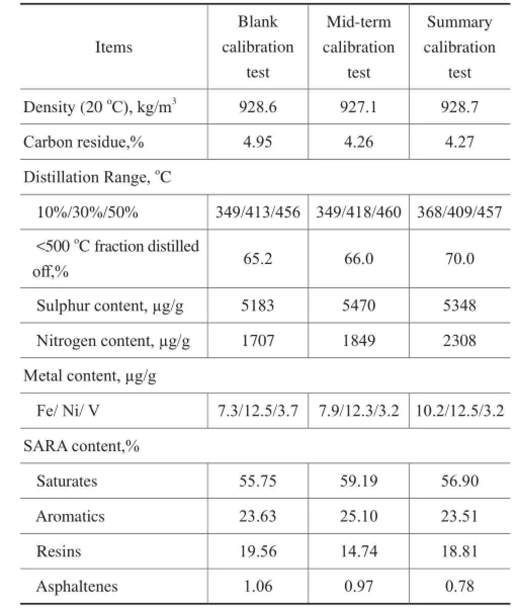
Table 2 Properties of the feedstock
It can be seen from the properties of FCC feedstock listed in Table 1 that the heavy metal content, the SARA content and the density of the feedstock used in three tests were close, except for the carbon residue of the feedstock used in the intermediate and summary calibration tests which was slightly lower than that of the feed oil used in the blank calibration test.
4.2 Primary properties of equilibrium catalyst
The analysis results of the equilibrium catalyst of three tests are presented in Table 3.
It can be seen from the data listed in Table 3 that the micro-activity of equilibrium catalyst collected from three calibration tests was around 65. During the blank calibration test, the fresh catalyst consumption was 1.727 kg/t. In comparison with the blank calibration test, the fresh catalyst consumption of intermediate and summary calibration tests was by 0.606 kg/t and 0.657 kg/t lower, respectively. In this way, with the catalyst consumption being reduced during the intermediate and summary calibration tests, the heavy metal content of the equilibrium catalyst remained close for the three cases, while the micro-activity of equilibrium catalyst of three tests maintained at a steady level, evidencing that the catalyst had good stability when it was examined in the course of the intermediate and summary calibration tests. The specific surface area of the equilibrium catalysts collected during the intermediate and summary calibration tests was higher than that measured during the blankcalibration test, indicating that the HSY zeolite contained in the HSC catalyst possessed good structural stability and high crystallinity retention, so that the activity and stability of the HSC catalyst had be improved.
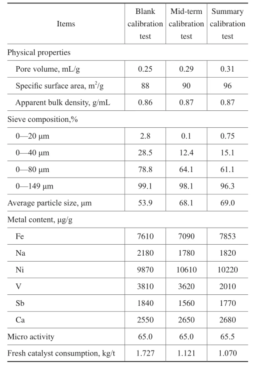
Table 3 Primary properties of equilibrium catalyst
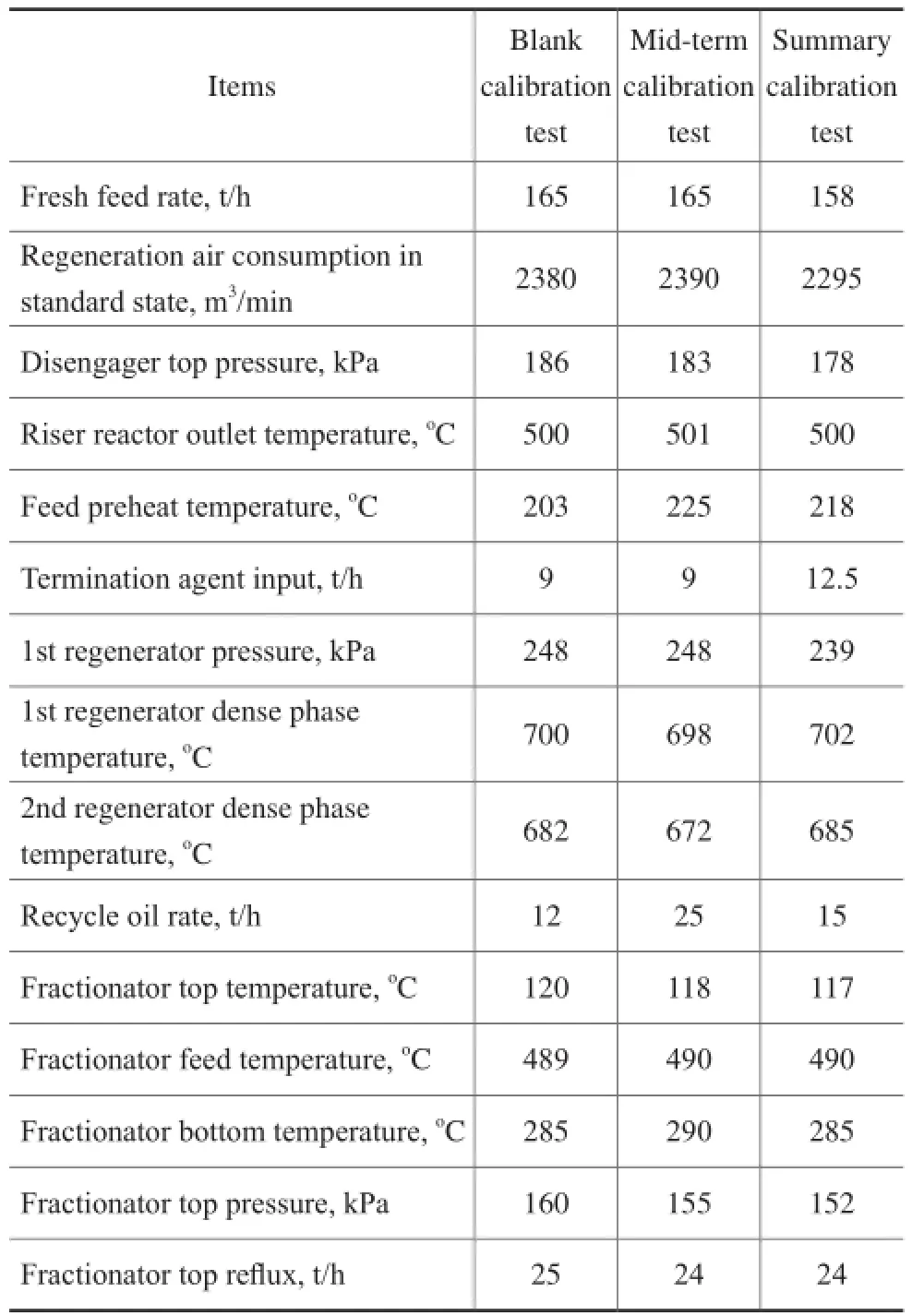
Table 4 The operating conditions of three calibration tests
Judging from the analysis result of particle size distribution, the fne powder content (with a particle size of 0—40 μm) demonstrated a declining tendency and the average particle size was smaller after HSC catalyst was applied, suggesting that the crushing strength of HSC catalyst was relatively high. It is generally acknowledged that the fluidization performance reaches the best when the fne powder content ranges from 15%—20%, which can enhance the transportation capacity without too much gas entrainment loss. When the amount of catalyst particles with a grain size of less than 20 μm increases signifcantly, the gas entrainment loss would be obvious. Starting from January 2010, fluctuation occurred to the fluidization process in the reaction-regeneration system, with the frequency of unloading catalyst increased and the catalyst loss decreased, indicating that the reduction of fine powder had a negative effect on fluidization. The catalyst particles, the size of which is smaller than 40 μm, are called the fine powder, while those catalyst particles with their size being larger than 80 μm are called the coarse grain. The ratio between the coarse grain content and the fine powder content is defined as the roughness coeffcient. A higher roughness coeffcient would lead to a worse fluidization status. Normally, the roughness coefficient should not be higher than 3. The blank calibration test had a roughness coeffcient of 0.74, while the roughness coefficient of mid-term calibration test and summary calibration test reached 2.89 and 2.58, respectively.
4.3 Operating conditions
The operating conditions of the reaction-regeneration system during three calibration tests are listed in Table 4.
4.4 Material balance
The material balance data of three calibration tests are listed in Table 5. The properties of dry gas and LPG from three calibration tests are listed in Table 6.
Judging from the statistics of material balance shown in Table 5, the gasoline yield of the summary calibration test was obviously higher than that of the blank calibrationtest, while the LCO yield of the summary calibration test was lower than that of the blank calibration test. The liquid yield increased after the HSC catalyst was applied. Compared with the blank calibration test, the total liquid yield of the mid-term calibration test and the summary calibration test increased by 0.52 and 1.34 percentage points, respectively. Upon comparing the data on yields of other products, it is known that the yields of dry gas and slurry from the summary calibration test were lower than those from the blank calibration test, while the coke yield was higher, and the LPG and gasoline yields were obviously higher than those from the blank calibration test. The gasoline yield increased by 5.05 percentage points and the LPG yield increased by 1.43 percentage points. In general, thanks to the reasonable design of catalyst, after the adoption of the HSC catalyst the cracking depth increased, and the catalyst had better capability of heavy oil conversion, while the distribution of products was also improved.
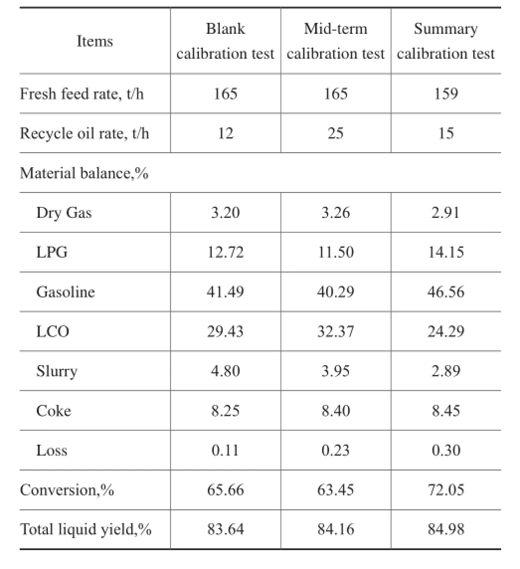
Table 5 Material balance
On account of the increased proportion of pipeline transported oil and the change in crude oil diet during the period of three calibration tests, the result of the tests was affected to some degree. In comparison to the blank calibration test, the feedstock became lighter during the summary calibration test, while the coke formation and the medium pressure steam output increased. The decrease of gasoline yield and increase of LCO were caused by the quality control needs. In the mid-term calibration test, the dry point of gasoline was lower than that in the blank calibration test by 8oC. According to the past experiences, the gasoline yield would increase by 2 percentage points if the dry point could be increased by 8oC. Judging from the statistics spanning from February 10thto 20th, 2010, the dry point of gasoline remained nearly the same as that of gasoline obtained during the blank calibration test, and the yield of gasoline increased by nearly 2 percentage points while the total liquid yield increased by 0.8 percentage points. By taking into account the yield of LPG and gasoline, the conversion of catalytic reaction was improved.
It can be seen from Table 6 that the content of C3+ components in dry gas from the intermediate and the summary calibration tests was close or less, as compared with that of the blank calibration test, indicating to the good quality of dry gas. Upon suggesting that the content of Ni and Sb was close, the H2/CH4volume ratio measured during the intermediate and the summary calibration tests was less than that of the blank calibration test, which could refect the strong metal tolerance ability of the HSC catalyst, resulting in an increased content of propylene in LPG.
Since the catalytic cracking reaction system is a complex reaction network of parallel sequence, the product distribution varies with different reaction depth. Therefore, besides comparing the product distribution directly, the selectivity of product should also be considered. According to the statistical data on product selectivity, during the blank calibration test the selectivity of dry gas, LPG, gasoline and coke was 4.87%, 19.37%, 63.19% and 12.56%, respectively. Compared with the results of the blank calibration test, during the mid-term calibration test, the selectivity of dry gas was by 0.26 units higher, and the selectivity of LPG was by 1.25 units lower, while the selectivity of gasoline was by 0.31 units higher, and the selectivity of coke was by 0.68 unitshigher. Compared to the results of the blank calibration test, during the summary calibration test, the selectivity of dry gas was by 0.83 units lower, and the selectivity of LPG was by 0.27 units higher, while the selectivity of gasoline was by 1.4 units higher, and the selectivity of coke was by 0.83 units lower. A conclusion could be drawn up from the above data that in comparison with the reference catalyst, the product selectivity, in particular the selectivity of dry gas, gasoline, and coke had been improved since the HSC catalyst was applied.
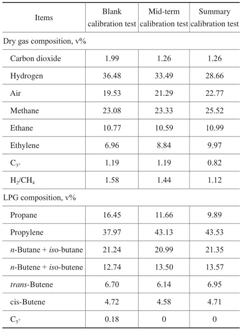
Table 6 Properties of dry gas and LPG
4.5 Properties of oil products
The primary properties of stabilized gasoline, LCO and slurry are listed in Tables 7—9.
Judging from the stabilized gasoline properties listed in Table 7, the research octane number (RON) of gasoline from the summary calibration test was 91.6, which was by 0.5 units higher than that from the blank calibration test. The motor octane number (МON) of gasoline from the summary calibration test was 81.0, which was the same as that from the blank calibration test. The induction period of stabilized gasoline was increased after the HSC catalyst was applied. Judging from the statistics on light diesel properties listed in Table 8, the light diesel fuel obtained from three calibration tests had low cetane number and poor quality.
The catalytic diesel fuel still needs to be processed by hydrotreating or blended with straight-run diesel fuel to satisfy the specifcation requirements.
It can be seen from Table 9 that the solid content of slurry from the intermediate and summary calibration tests decreased as compared to that from the blank calibration test, suggesting that the catalyst had a better performance than the contrast catalyst. The result of these tests indicates that the density of slurry and carbon residueincreased, while the quality of slurry worsened and turned heavier. Compared with the contrast catalyst, the HSC catalyst possessed stronger bottoms conversion ability.
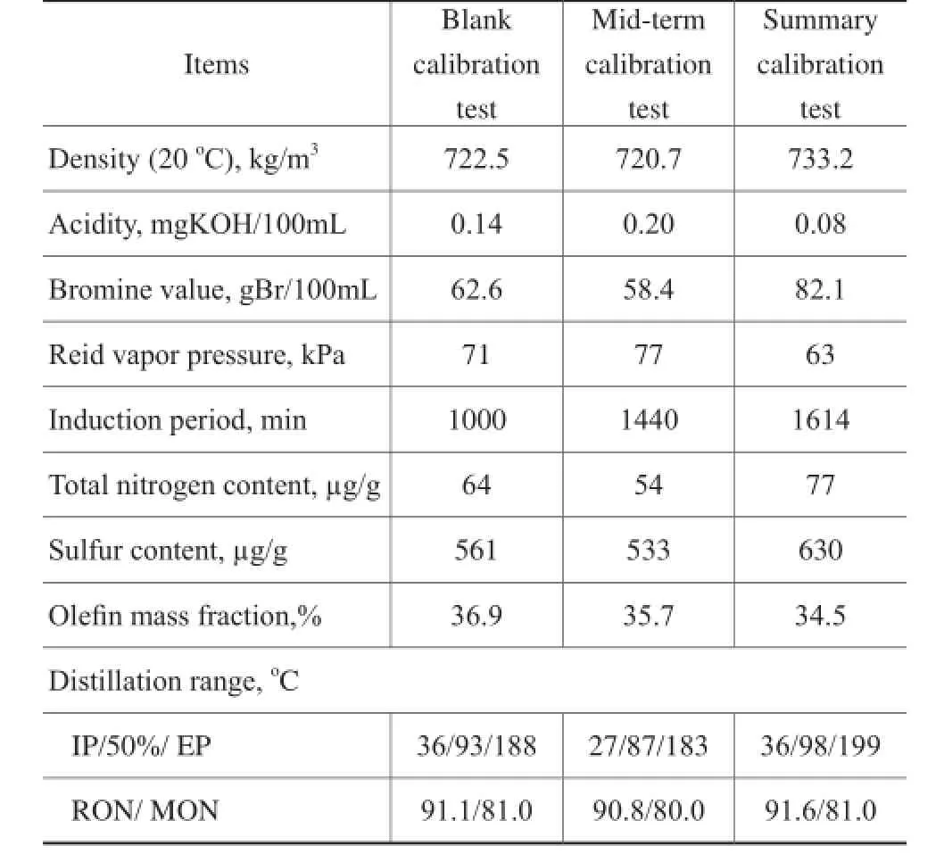
Table 7 Properties of stabilized gasoline
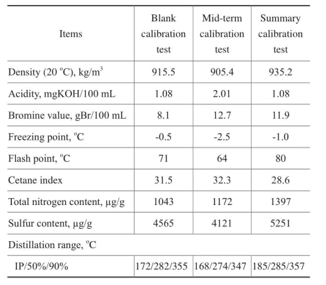
Table 8 Properties of LCO
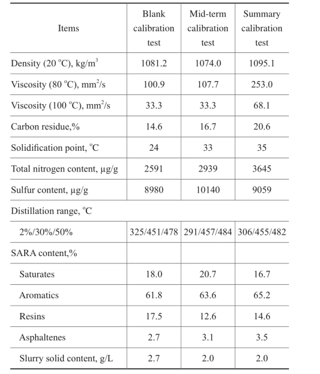
Table 9 Properties of slurry
4.6 Daily statistical analysis report
The statistics of industrial test and daily production starting from January 2009 to the end of 2015 had been collected and made into charts. Figures 1—4 reveal the trends of change in feedstock properties and product yield before and after the HSC catalyst was applied, serving as the basis of daily statistical analysis. Among them, the HSC catalyst began to join the system 180 days after the start of statistics recording. The HSC catalyst had been used in the FCC unit of the refinery A for about 2,500 days by the end of 2015.
Figure 1 shows the tendency of metal content in feedstock with time on stream. The statistical results of Figure 1 show that the vanadium content in feedstock was almost unchanged, and the nickel content increased slightly, while the iron content increased significantly with time on stream. The results revealed that the properties of feedstock were slightly heavier during the long term industrial application of the HSC catalyst as compared with that of the contrast catalyst.
Figure 2 and Figure 3 show the tendency of gasoline yield and total liquid yield with time on stream, respectively. Figure 4 shows the tendency of slurry yield with time on stream. It can be seen from Figures 2—4 that the tendency of the total liquid yield and gasoline yield increased obviously while the tendency of oil slurry yield declined signifcantly after application of the HSC catalyst, which was consistent with the result of calibration tests.
The statistical result has confrmed that industrial application result of the HSC catalyst in long term is consistent with that of the industrial calibration tests. It also indicates that the HSC catalyst demonstrates a strong ability to convert heavy oil and can achieve high gasoline yield and total liquid yield as compared with the contrast catalyst.
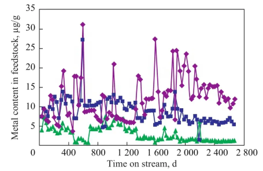
Figure 1 Tendency of metal content in feedstock◆—Fe content;■—Ni content;▲—V content
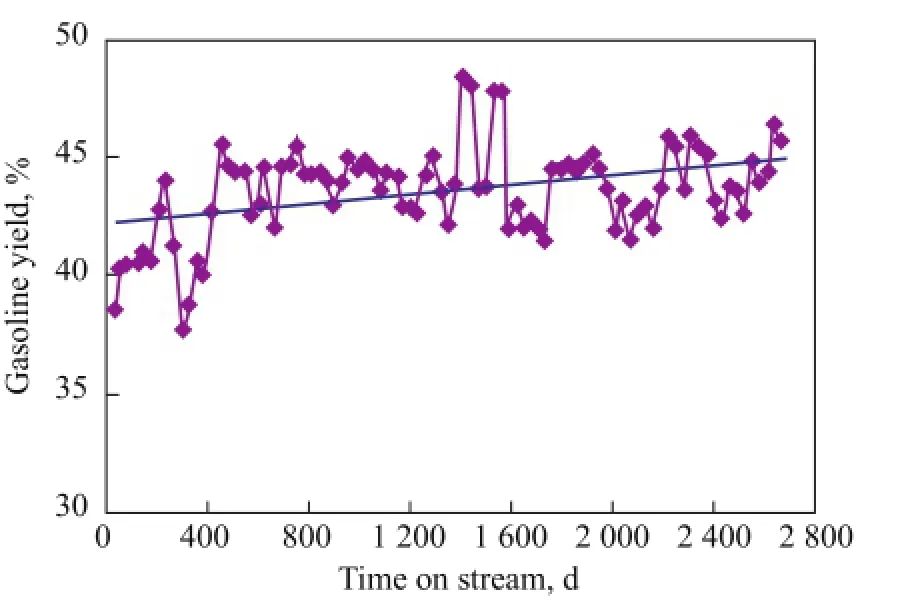
Figure 2 Tendency of gasoline yield
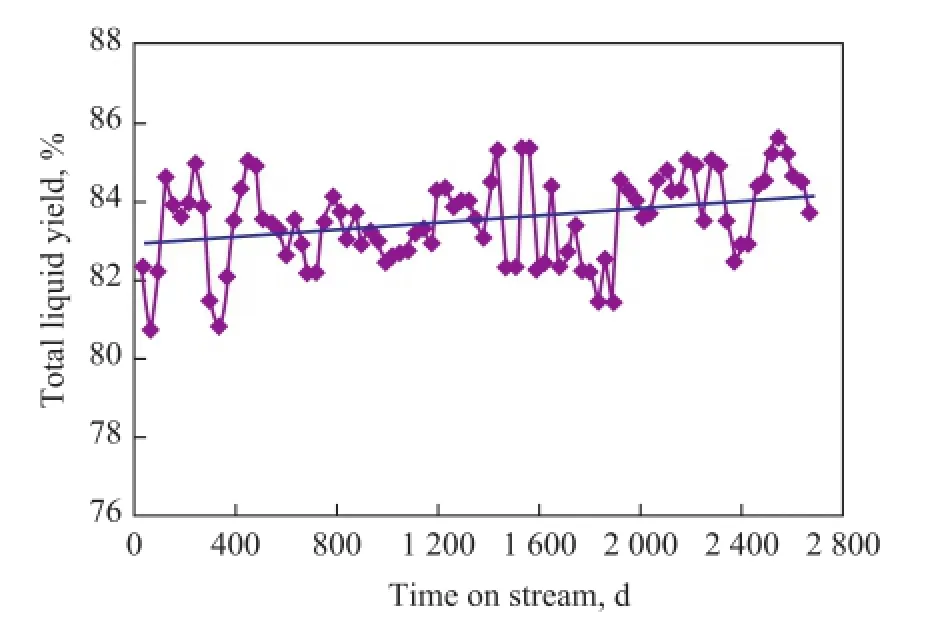
Figure 3 Tendency of total liquid yield
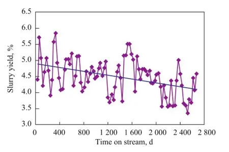
Figure 4 Tendency of oil slurry yield
3 Conclusions
Compared with the contrast catalyst, the following conclusions can be drawn from the results of industrial tests and application of the HSC catalyst on RFCC unit atthe refnery A.
The total liquid yield obtained from the intermediate and summary calibration tests of the HSC catalyst increased by 0.52 and 1.34 percentage points along with the reduction of dry gas and slurry yield. During the summary calibration test, the gasoline yield and LPG increased by 5.05 and 1.43 percentage points, respectively. The product selectivity especially that related with the dry gas, gasoline and coke had been improved. The content of propylene in LPG increased without signifcant change in the properties of oil products.
During the industrial application, the catalyst consumption and solid content of slurry showed a declining tendency, while the total liquid yield and gasoline yield showed an increasing trend and the slurry yield displayed a decreasing tendency.
The HSC catalyst possessed high stability, a relatively strong metal tolerance, and high catalyst crushing strength. Also, the HSC catalyst showed strong capability of heavy oil conversion, satisfactory product distribution and selectivity, while the yield of high value products was obviously higher than that of the contrast catalyst. The industrial application has brought about great economic benefts.
Reference
[1] Sadeghbeigi R. Fluid Catalytic Cracking Handbook[М]. 2nd Edition. Houston: Gulf Professional Publishing, 2000: 1-39
[2] Chen Junwu. Catalytic Cracking Process and Engineering [М]. Beijing: SINOPEC Press, 2005: 199-214 (in Chinese)
[3] Grobet P J, Jacobs P A, Beyer H K. Study of the silicon tetrachloride dealumination of NaY by a combination of NМR and IR methods[J]. Zeolites, 1986, 6(1): 47-50
[4] Wang Yingjun, Sun Yujia, Suo Yanhua, et al. Research progress in dealumination of USY zeolites[J]. Industrial Catalysis, 2015, 23(11): 849-853 (in Chinese)
[5] Skeels G W, Breck D W. Zeolite Chemistry. V. Substitution of Silicon for Aluminum in Zeolite via Reaction with Aqueous Fluorosilicate[C]//Proc. 6thInternational Zeolite Conf. (Butterworths): 1984, 87-96
[6] Мartens J A, Grobet P J, Jacobs P A. The chemistry of the dealumination of faujasite zeolites with silicon tetrachloride[J]. Studies in Surface Science and Catalysis, 1991, 63: 355-379
[7] Shu Yuying, Travert A, Schiller R, et al. Effect of ionic radius of rare earth on USY zeolite in fluid catalytic cracking: Fundamentals and commercial application[J]. Topics in Catalysis, 2015, 58(4/6): 334-342
[8] Li Xuejin, Qiao Ke, He Lifeng, et al. Combined modifcation of ultra-stable Y zeolites via citric acid and phosphoric acid [J]. Applied Petrochemical Research, 2014, 4(4): 343-349
[9] Han Guo, Sun Xiaoyan, Fan Hongfei, et al. Effects of different modification methods on structure and acidity of Y zeolite[J]. Petrochemical Technology & Application, 2015, 33(3): 208-211 (in Chinese)
[10] Zhang Zhimin, Zhou Lingping, Yang Lin, et al. Research and development of novel heavy oil catalytic cracking catalyst HSC-1[J]. Acta Petrolei Sinica (Petroleum Processing Section), 2012, 28(1): 1-6 (in Chinese)
Successful Application of Novel α-Methylstyrene Hydrogenation Catalyst at Yanshan Petrochemical Company
The SHP-A1 type catalyst for hydrogenation of α-methylstyrene (AМS) developed by the SINOPEC Shanghai Petrochemical Research Institute (SPRI) has been successfully applied in the No. 1 phenol unit at the Third Chemical Plant of Yanshan Petrochemical Company at the frst attempt of commissioning. The said catalyst is the frst AМS hydrogenation catalyst developed independently by the domestic institution and successfully applied in the industry, symbolizing the preliminary success of SPRI in terms of disseminating its hydrogenation technology into the phenol-acetone process.
The No. 1 phenol unit at the Third Chemical Plant has a design capacity of 160 kt/a, which used to adopt overseas catalyst before commissioning of the AMS hydrogenation unit. On July 25, 2016 the SHP-A1 type hydrogenation catalyst was successfully applied in the phenol unit at the first attempt of operation. At present this hydrogenation unit operates smoothly, and the temperature distribution in the reactor bed is rational to deliver qualifed product with the expected test targets fulflled.
Received date: 2016-11-24; Accepted date: 2017-01-09.
Zhang Zhimin, E-mail: zhangzm.chji@ sinopec.com.
- 中国炼油与石油化工的其它文章
- Tribological Characteristics of Graphene as Lithium Grease Additive
- Regeneration of Simulated Deactivated Hollow Titanium Silicate Zeolite by Secondary Crystallization in the TPAOH Solution
- A FCC Catalyst Prepared by in situ Technique Based on Application of Filter Residue and Kaolin
- Mesoporous Ti-Mo Mixed Oxides Catalyzed Transformation of Carbohydrates into 5-Hydroxymethylfurfural
- Infuence of Different Hydrocarbon Molecules on Physical Properties of Mineral Base Oils
- Study on Rheological Characteristics of a Grease Used in High Speed Bearing