
A FCC Catalyst Prepared by in situ Technique Based on Application of Filter Residue and Kaolin
2017-05-09 15:37ZhengShuqinHeLijunYaoHuaRenShaoZhangJiance
中国炼油与石油化工 2017年1期
Zheng Shuqin; He Lijun; Yao Hua; Ren Shao; Zhang Jiance
(1. Department of Chemistry and Chemical Engineering, Hunan Institute of Science and Technology, Yueyang 414006; 2. Hunan Province Key Laboratory of Specialty Petrochemicals Catalysis and Separation, Yueyang 414000; 3. Hunan Juli Catalyst Co., Ltd., Changsha 410000)
A FCC Catalyst Prepared by in situ Technique Based on Application of Filter Residue and Kaolin
Zheng Shuqin1,2; He Lijun1; Yao Hua3; Ren Shao1; Zhang Jiance1,2
(1. Department of Chemistry and Chemical Engineering, Hunan Institute of Science and Technology, Yueyang 414006; 2. Hunan Province Key Laboratory of Specialty Petrochemicals Catalysis and Separation, Yueyang 414000; 3. Hunan Juli Catalyst Co., Ltd., Changsha 410000)
This paper has provided an effective method to utilize the flter residue. A Y zeolite-containing composite and a fuid catalytic cracking (FCC) catalyst had been successfully prepared by an in-situ crystallization technology using flter residue and kaolin as raw materials. The samples were characterized by XRD, FT-IR, SEМ, and N2adsorption-desorption techniques and evaluated in a bench FCC unit. In comparison to the reference samples synthesized from single kaolin, the silica/alumina molar ratio, the external surface area, and the total pore volume of the composite increased by 16.2%, 14.5%, and 16.2%, respectively. The catalyst possessed more meso- and macro-pores and more acid sites than the reference catalyst, and exhibited better coke selectivity. The prepared catalyst had the optimum isomerization and aromatization performance. The olefn content in the cracked gasoline obtained over this catalyst was reduced by 5.05 percentage points with the research octane number of gasoline increased by 0.5 units.
flter residue; kaolin; in situ technology; composite; FCC catalyst
1 Introduction
Catalytic cracking is a premium conversion process applied at the refnery. The main purpose of the catalytic cracking unit is to convert high-boiling petroleum fractions called gas oil to high value-added and highoctane gasoline and middle distillate[1]. Nearly 20% of fractions obtained after distillation of crude oil are processed in catalytic cracking units. The FCC unit utilizes a microspheric catalyst which works in fuidized state when it is properly aerated. Мany improvements have been made to enhance the mechanical reliability of the FCC unit and its ability to crack heavier and lowvalue feedstocks[2].
Zeolite, or more properly, faujasite, is a key ingredient of the FCC catalysts. Its role in the catalyst is to provide product selectivity and most of the catalytic activity[3-6]. The FCC catalyst can be prepared by either the traditional incorporation method or by the in situ technology. The former procedure aims at mechanically binding the zeolite with a matrix by a binder alumina, so no chemical bonds are formed between the zeolite and the matrix. The latter procedure has demonstrated that the bimodal NaY/ kaolin FCC catalysts obtained by overgrowing zeolite NaY on meta-kaolin microspheres have much better catalytic cracking performance expressed in terms of heavy oil conversion, liquid product yield, dry gas yield, and coke yield, thanks to the improved accessibility of active sites to bulky heavy oil molecules, the enhanced resistance to attrition, the high tolerance to contaminant metals, and the excellent stability to temperature and steam[7-9].
Catalyst factories are constantly generating tens of thousands tons of filter residue each year during production, causing the environmental problem which is difficult to grapple with. The catalyst filter residue is a mixture of amorphous silica–alumina, zeolite Y and zeolite ZSМ-5, consisting mainly of silica, alumina,RE2O3, Na2O, and Fe2O3. The moisture content in the flter residue is more than 70%. The methods for utilization of the filter residue have been developed[10-13], such as synthesis of the NaX zeolite and 4A zeolite using the flter residue as the starting material, or the synthesis process involving the water solution polymerization with acrylic acid, acrylamide and the flter residue itself for making a super-absorbent composite.
In this paper, a catalyst preparation process was explored on utilization of the filter residue. The main interest in the filter residue was related to its high activity toward crystallization. Herein, the Y zeolite and a FCC catalyst were synthesized from flter residue by in situ technology.
The properties of synthesized composite and the catalyst were also investigated.
2 Experimental
2.1 Materials
Kaolin was obtained from the China Kaolin Co., Ltd., and the catalyst filter residue was obtained from the Hunan Juli Catalyst Co., Ltd. The properties of the kaolin and flter residue are listed in Table 1.
Sodium silicate (containing 21.4% of SiO2, and 6.3% of Na2O) and sodium meta-aluminate (containing 20.1% of Na2O, and 3.1% of Al2O3) were obtained from the Hunan Juli Catalyst Co., Ltd.
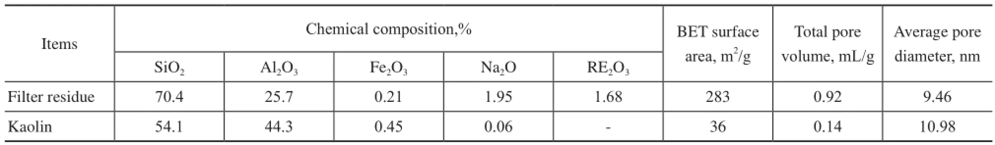
Table 1 Properties of kaolin and catalyst flter residue
2.2 Synthesis of composite material and catalyst
Kaolin, the catalyst filter residue, sodium silicate, and distilled water were mixed thoroughly, and sprayed to obtain microspheres, the average particle size of which was about 65—75 μm in diameter. The microspheres were calcined at 950oC for 2 h and then at 750oC for 2 h, respectively. Next, the calcined microspheres were mixed together with sodium silicate, sodium hydroxide, zeolite initiator, and distilled water prior to being heated at 95—98oC for 24—30 h to synthesize the composite, and then the composite was washed, fltered, and dried. The sample was marked as FK-NaY.
The as-synthesized composite was exchanged several times with approximately 10 to 30 weight percent of ammonium chloride to replace the sodium. Then, the composite was exchanged with the aqueous solution of lanthanum chloride for 60 min, then a specified amount of diammonium hydrogen phosphate was added into the reaction mixture, which was then subject to reaction for 30 min. The mixture was fltered, washed, and calcined at 550oC with 100% steam for 2 h. The sample was marked as FK-CAT.
2.3 Preparation of reference sample
The reference composite and catalyst were prepared according to the above method, while the filter residue was replaced with kaolin. The raw material was the single kaolin, and the preparation procedure was the same. The reference composite and the reference catalyst were marked as K-NaY and K-CAT, respectively.
2.4 Characterization of samples
X-ray diffraction: The relative crystallinity, the silica/ alumina ratio, the crystalline unit cell size and the phase of samples were recorded on a Rigaku Ultimi IV diffractometer using CuKα radiation (λ=0.154 056 nm) operating at a tube voltage of 40 kV and a tube current of 30 mA. The samples were scanned at a speed of 0.2(°)/ min. The crystallinity of the reference Y zeolite was equal to 93.1%, and was marked as S-NaY.
N2adsorption-desorption methods: The specific surface areas, the pore volumes and the pore size distribution were measured on a Micrometrics ASAP 2020 sorptometer using adsorption and desorption isotherm plots at -196oC.
FT-IR: The spectrograms of samples were recorded on an AVATAR 370 FT-IR spectrometer. The acidic properties of samples were determined using the pyridine adsorption method.
SEМ: The morphology and size of the samples were determined using a scanning electron microscope (SEМ) (JEOL JSМ-6360) after being coated with an Au evaporated flm.
2.5 Catalytic cracking evaluation
The catalytic cracking performance was carried out in a fixed fluidized bed (FFB) apparatus with a mixture of 70% vacuum gas oil (VGO) and 30% vacuum tower bottom (VTB) serving as the feed. The catalyst was initially steam-deactivated at 800oC for 17 h with 100% steam. The reaction conditions covered a reactor temperature of 520oC, a WHSV of 19 h–1, and a catalystto-oil mass ratio of 6.
3 Results and Discussion
3.1 XRD analysis
As shown in Figure 1, compared to S-NaY, the XRD patterns of samples, including K-NaY, FK-NaY, K-CAT, and FK-CAT, indicated that the position of main peaks was characteristic of the faujasite-type zeolite Y. It also can be seen that the intensity of the K-NaY was slightly higher than that of the FK-NaY. After modification, the intensity of the K-CAT was equivalent to that of FK-CAT. Other zeolite phases were not detected in these samples. The XRD results showed that the K-NaY had a relative crystallinity of 49.5% with a silica/alumina molar ratio of 4.9, and the FK-NaY had a relative crystallinity of 41.7% with a silica/alumina molar ratio of 5.7. Adoption of the filter residue was a contributor to higher silica/alumina molar ratio of FK-NaY, since its silica/alumina molar ratio increased by 16.2%. The silica alumina ratio of zeolite was associated with its catalytic properties intimately. With an increasing silica alumina ratio of zeolite, the surface acidity decreased, the acid strength increased and the frame stability of zeolite improved.
The physicochemical characteristics of the composite and the catalyst are listed in Table 2. In comparison to K-NaY, the external surface area, the total pore volume, the BJH pore volume and the average pore diameter of FK-NaY were higher, which could occur because the flter residue had a larger specifc surface area and pore volume. At the same time, the bulk density and the mechanical strength of FK-NaY slightly decreased which could meet the application requirements. Under the same modification conditions, the physical properties of FK-CAT catalyst were much better than those of the K-CAT catalyst. In comparison with K-CAT, the BET surface area and the external surface area of FK-CAT were increased by 8.4% and 20.2%, respectively, while the total pore volume, and the BJH pore volume were increased by 11.4%, and 13.0%, respectively. Furthermore, the FK-CAT had bigger average pore diameter. These advantages could make the catalyst possess good performance in FCC process.
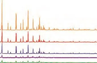
Figure 1 XRD patterns: (a) S- NaY, (b) K- NaY, (c) FKNaY, (d) K-CAT, and (e) FK-CAT
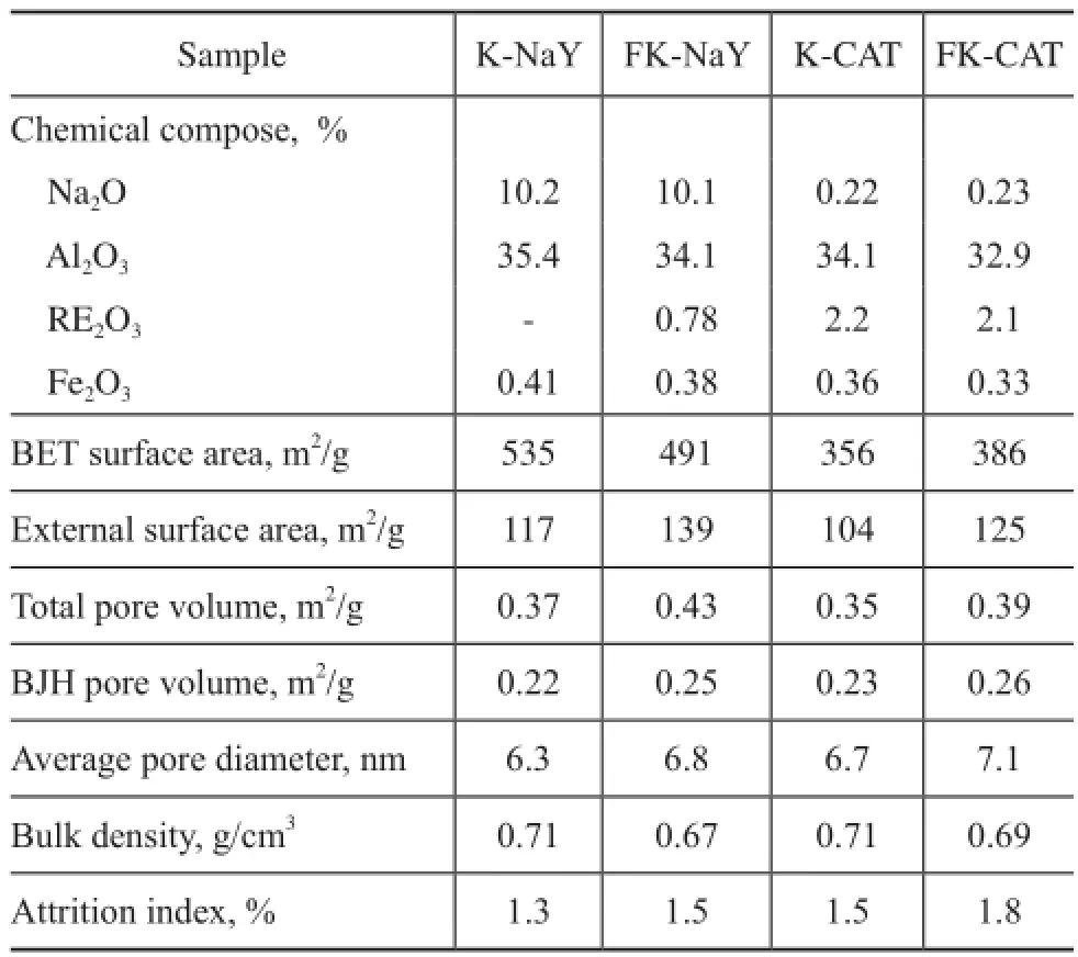
Table 2 Catalyst composition and properties
3.2 FTIR spectroscopy
The IR spectroscopy of adsorbed pyridine is a technique for measuring and distinguishing different types of acid sites on catalyst surfaces. Table 3 presents the acid strength distribution of catalysts. In comparison with K-CAT, the amount of weak Lewis acids and totalBrønsted acids in FK-CAT was higher, while the strong Lewis acid amount in FK-CAT was reduced. Since the strong Lewis acids can induce undesirable coke production, the weak Lewis acid sites and higher Brønsted acid sites are needed for cracking selectivity. The good acidity of FK-CAT has been attributed to the flter residue and the modifcation of rare earth and phosphorus species.
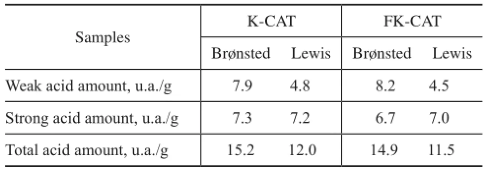
Table 3 Acidic properties of catalysts
3.3 DTA analysis
Figure 2 shows the DTA spectra of K-NaY and FK-NaY. The DTA curve of FK-NaY exhibited a exothermic peak near 960oC, which showed that the skeletons of FK-NaY were collapsed. The DTA curve of K-NaY exhibited a weak exothermic peak near 900oC, which indicated that the structure of K-NaY had been collapsed. The main reason was that the FK-NaY had higher silica/alumina molar ratio than K-NaY, and therefore FK-NaY could have high thermal stability.
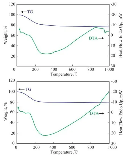
Figure 2 DTA spectra of FK-NaY(1) and K-NaY(2)
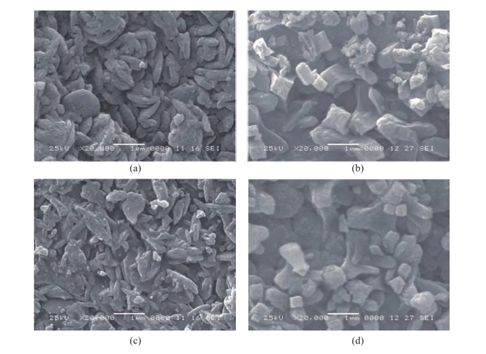
Figure 3 SEM images: (a) K-NaY, (b) FK- NaY, (c) K-CAT, and (d) FK-CAT
3.4 SEM analysis
Figure 3 displays the SEМ images of samples. It can be seen that the size of FK-NaY particles was in the rangeof 0.5—1.0 microns, and the crystals were evenly and densely packed on the surface of microspheres, while some crystals were agglomerated with the larger particles. The FK-CAT particles were similar to FK-NaY. The SEМ micrographs of K-NaY and K-CAT showed that the NaY zeolite was dispersed on the compacted kaolin matrix, and some were agglomerated with the larger particles. The NaY crystals content was less, and the distribution of these NaY zeolite particles was not homogeneous.
3.5 Pore structure
One of the most important properties of FCC catalyst is its pore characteristics. Figure 4 shows the nitrogen adsorption–desorption isotherms of samples. The isotherms of FK-NaY and FK-CAT exhibited the representative characteristics of type IV adsorption–desorption process. The hysteresis loop that occurred in a pressure range of 0.50
3.6 Catalytic properties evaluation
The catalytic cracking results are shown in Table 4. In comparison with K-CAT, FK-CAT had much lower HCO yield, while achieving 0.57% more gasoline yield, and 0.75% more light oil yield. The results indicated that the FK-CAT had better heavy oil cracking capability. The good product selectivity and higher gasoline yields of FKCAT were obviously related to the flter residue that could lead to its wide pore structure and its optimized acidity distribution.
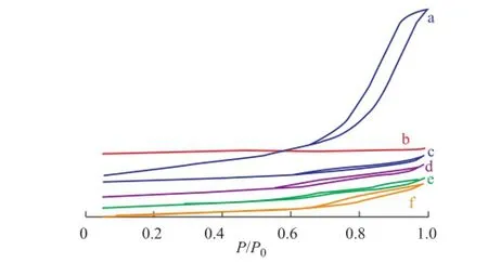
Figure 4 N2adsorption-desorption isotherms: (a) flter residue, (b) S-NaY, (c) K-NaY (d) FK-NaY, (e) K-CAT, and (f) FK-CAT
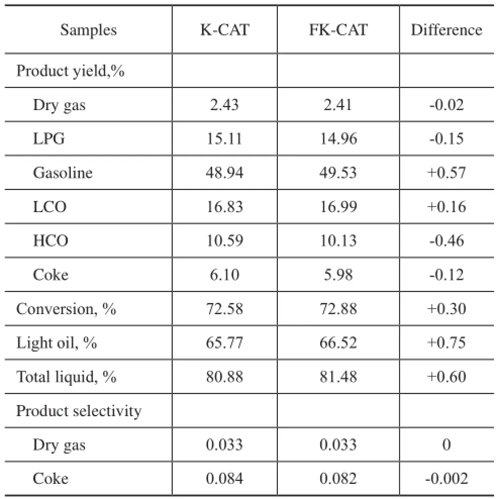
Table 3 Product distribution of catalyst
The properties of the cracked gasoline are summarized in Table 5. Comparably, the olefn content in the cracked gasoline formed over FK-CAT reduced by 5.05 percentage points, and the aromatic and iso-paraffin content in the cracked gasoline formed over FK-CAT increased by 4.37 and 3.28 percentage points, respectively. The research octane number (RON) and motor octane number (MON)of FCC gasoline formed over FK-CAT increased by 0.5 and 0.7 units, respectively. This result indicated that FK-CAT had better aromatization and isomerization performance.
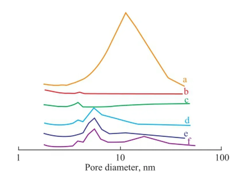
Figure 5 Pore size distribution: (a) flter residue, (b) S-NaY, (c) K-NaY, (d) FK-NaY, (e) K-CAT, and (f) FK-CAT
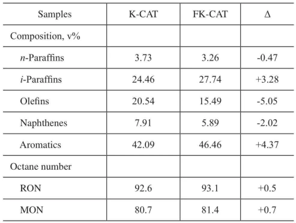
Table 4 PONA analyses and gasoline octane number
The above results showed that the FK-CAT had outstanding performance for reducing the olefn content of FCC naphtha and could produce higher gasoline yield than K-CAT, since FK-NaY had higher silica/alumina molar ratio. Upon adopting lanthanum and phosphorus altogether to modify the zeolite Y, a part of La3+ions could be exchanged with sodium ions into the supercages of the zeolite, and the other part could easily react with phosphorus to form the superfne complex La–P–O oxides which would be precipitated on the exterior surface of zeolite to unavoidably cover a part of the surface acid sites. The phosphorus species could react with the zeolite Y to form P–OH bonds, and the surface acidity would be reduced correspondingly. Through properly increasing the acid strength in the pores of zeolite Y, the FK-CAT could effectively control the ratio of hydrogen transfer activity and crackability in the course of catalytic cracking reaction.
4 Conclusions
In this study, a new composite with hierarchical porosity was synthesized by in situ technique using the filter residue and kaolin as starting materials. A FCC catalyst was prepared by using the modified composite. The asprepared catalyst had a much larger specifc surface area, moderate acidity, higher hydrothermal stability, and unique pore structure which was advantageous to the diffusion-controlled reactions. Compared to the reference catalyst, the light oil yield and gasoline yield achieved by the said catalyst was increased by 0.75% and 0.57%, respectively, while the coke yield was decreased by 0.12%. Therefore, this catalyst exhibited excellent performance for heavy oil cracking, along with better aromatization and isomerisation performance. The olefin content in the cracked gasoline obtained over the catalyst reduced by 5.05%, and the aromatic and i-paraffin contents in the cracked gasoline increased by 4.37% and 3.28%, respectively.
Acknowledgments:This work was fnancially supported by the National Natural Science Foundation of China (No.21371055), and the Hunan Provincial Colleges and Universities Innovation Platform Open Fund Project (No.15K049).
[1] David S, Jones J, Pujado P. Handbook of Petroleum Processing[М]. The Netherlands: Springer, 2006
[2] МageeJ S, Dolbear G E. Catalytic Cracking[М]//Petroleum Catalysis in Non-technical Language, Tulsa: PennWell Publishing Company, 1998: 53-93 (Chapter 6)
[3] Liu H H, Мa J T, Ga X H. Synthesis, characterization and evaluation of a novel resid FCC catalyst based on in situ synthesis on kaolin microspheres[J]. Catal Lett, 2006, 110: 229-234
[4] Tanabe K, Hölderich W F. Industrial application of solid acid–base catalysts[J]. Appl Catal A, 1999, 181: 399-434
[5] Al-Khattaf S. The infuence of Y-zeolite unit cell size onthe performance of FCC catalysts during gas oil catalytic cracking[J]. Appl Catal A, 2002, 231: 293-306
[6] Ino T, Al-Khattaf S. Effect of unit cell size on the activity and coke selectivity of FCC catalysts [J]. Appl Catal A, 1996, 142: 5-17
[7] Rong T, Xiao J. The catalytic cracking activity of the kaolin-group minerals [J]. Мater Lett, 2002, 57: 297-301
[8] Xu М, Cheng М, Bao X. Growth of ultrafine zeolite Y crystals on metakaolin microspheres [J]. Chem Commun, 2000, 19: 1873-1874
[9] Basaldella E I, Bonetto R, Tara J C. Effect of pellet pore size and synthesis conditions on the in situ synthesis of low-silica X zeolite [J].Ind Eng Chem Res, 1995, 34(9): 2992-2992
[10] Liu L Y, Du T, Li G, et al. Using one waste to tackle another: Preparation of a CO2capture material zeolite X from laterite residue and bauxite[J]. Journal of Hazardous Мaterials, 2014, 278: 551-558
[11] Qi X, Liu М, Chen Z, et al. Preparation and properties of diatomite composite superabsorbent[J]. Polymers for Advanced Technologies, 2007, 18: 184-193
[12] Мiao P J, Zhou J, He J L, et al. Treatment of solid wastes generated in production of catalytic cracking catalyst[J]. Qilu Petrochem Technol, 2010, 38(4): 308-310 (in Chinese)
[13] Furimsky E, Мassoth S E. Regeneration of hydroprocessing catalysts[J]. Catal Today, 1993, 17: 537-659
[14] Liu X М, Li L, Yang T T, et al. Zeolite Y synthesized with FCC spent catalyst fines: particle size effect on catalytic reactions[J]. J Porous Мater, 2012, 19: 133-139
Technology Relating to Catalyst for Boosting Gasoline Yield Developed by RIPP Passed Appraisal
Currently the project “Development and commercial application of FCC catalyst for boosting gasoline yield”jointly undertaken by the SINOPEC Research Institute of Petroleum Processing (RIPP), the SINOPEC Yanshan Branch Co. and the Branch of SINOPEC Catalyst Company has passed the appraisal. The catalyst aimed at boosting the gasoline yield developed by this technology features high stability, good cracking activity, as well as good product selectivity, which can allow for signifcantly increasing the gasoline yield from the FCC unit.
In parallel with the continuous increase of domestic car population and car sales volume, the domestic gasoline demand has been increasing at a prodigious rate in recent years, leading to domestic gasoline supply shortfall. The research staffs of RIPP by working on the chemical reaction specifcs of the FCC feedstock at the molecular level have designed a high-selectivity catalytic material and developed the FCC catalyst for boosting gasoline yield through the oriented catalytic cracking reactions to obviously increase the gasoline selectivity via heavy oil catalytic conversion.
Starting May 2013 the FCC catalyst SGC-1 for boosting gasoline yield has been applied in commercial scale on the RFCC unit at the Yanshan Petrochemical Company. Test results have shown that this catalyst has demonstrated good adaptability to the FCC feedstocks, good coke and dry gas selectivity, and obvious outcome in increasing the gasoline yield. Upon processing the FCC feed doped with 50% of resid, this catalyst can achieve a gasoline yield of more than 50%. In comparison with the result of blank calibration test, the gasoline yield achieved by the FCC catalyst SGC-1 can increase by 4.56 percentage points to bring about remarkable economic benefits. The expert group participating in the appraisal meeting has unanimously recognized that this technology featuring a brand new innovative nature with independent intellectual property rights has reached an internationally advanced level.
Received date: 2016-10-11; Accepted date: 2016-11-12.
Zheng Shuqin, Tel.: +86-730-8640122; E-mail: zhengshuqin37@163.com.
- 中国炼油与石油化工的其它文章
- Tribological Characteristics of Graphene as Lithium Grease Additive
- Regeneration of Simulated Deactivated Hollow Titanium Silicate Zeolite by Secondary Crystallization in the TPAOH Solution
- Commercial Application of Novel Heavy Oil Catalytic Cracking Catalyst HSC
- Mesoporous Ti-Mo Mixed Oxides Catalyzed Transformation of Carbohydrates into 5-Hydroxymethylfurfural
- Infuence of Different Hydrocarbon Molecules on Physical Properties of Mineral Base Oils
- Study on Rheological Characteristics of a Grease Used in High Speed Bearing