
浓缩风能装置扩散管流场模拟验证及其凸缘结构优化设计
2017-11-01 23:07林俊杰王伟龙
农业工程学报 2017年18期
林俊杰,田 德,陈 静,王伟龙,邓 英
浓缩风能装置扩散管流场模拟验证及其凸缘结构优化设计
林俊杰,田德※,陈静,王伟龙,邓英
(新能源电力系统国家重点实验室(华北电力大学),北京 102206)
浓缩风能装置的扩散管结构直接影响浓缩风能型风电机组的输出功率。为提高浓缩风能装置的浓缩效率,以浓缩风能装置为研究对象,采用数值模拟方法,研究扩散管凸缘的几何参数对浓缩风能装置内部流场特性的影响规律;并通过试验验证数值模拟的可靠性。结果表明:扩散管凸缘结构能够明显提高浓缩风能装置对自然风的加速作用和风能利用率;且装置内部流场的流速和风轮扫掠面积上的可利用风能随着凸缘高度的增加而增大。综合分析可得,带有为450 mm、凸缘角度为+9°的扩散管凸缘的浓缩风能装置模型流场流速和可利用风能较高;与原始模型相比,其内部流场最大流速提高了30.738%,可利用风能提高了84.26%,是所研究模型中流场性能较佳的浓缩风能装置结构。
风能;流场;数值模拟;浓缩风能装置;扩散管;凸缘
0 引 言
浓缩风能装置是浓缩风能型风电机组[1-8]的核心部件,而扩散管凸缘能够增强浓缩风能装置的抽吸作用,提高浓缩风能装置内部流场的流体流速,同时降低装置内部的风能波动性,提高机组的风力发电质量。
为提高浓缩风能型风电机组的发电效率、降低机组发电成本,许多国内外研究人员对浓缩风能装置结构及流场性能进行了研究[9-17]。Takagi等[18]通过模拟研究表明扩散管对风电机组的输出功率具有一定的提高作用,且扩散管内流体流速的大小取决于扩散管的形状。Jafari等[19]通过研究不同形状的扩散管模型得出:扩散管面积比的提高能够大幅度降低内部流场压强,提高质量流量;Kosasih等[20]则对比研究了入流湍流度对普通型和带有扩散管的小型风电机组性能的影响;Ohya等[21]对带有凸缘扩散管优化结构的小型风电机组进行了风洞试验与现场测试研究,表明其输出功率比普通型风电机组提高了4~5倍;田德等[22]应用数值模拟方法对浓缩风能装置内部流场性能进行模拟研究,得出了浓缩风能装置的收缩段、中央圆筒和扩散段的尺寸参数变化对内部流场特性的影响规律,为浓缩风能装置的结构优化提供了依据。
为了研究扩散管凸缘结构对浓缩风能装置内部流场性能的影响规律,在具有风切变的来流条件下,对扩散管凸缘几何参数不同的浓缩风能装置(不安装风轮)的内部流场进行数值模拟分析。
1 浓缩风能理论
在单位时间(1 s)内流过风轮的空气所具有的风能为
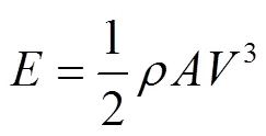
式中为单位时间内流过风轮的空气所具有的风能,J;为空气密度,kg/m3;为风轮扫掠面积,m2;为风速,m/s。
根据式(1),浓缩风能理论[23]可这样描述:在不消耗其他能源的情况下,使自然风速增大为倍,则风能将增加为3倍。
2 数值模拟计算
2.1 建立几何模型
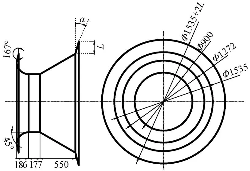
浓缩风能装置几何模型以200 W风电机组模型为原型,具体选用参数为:增压板最大截面直径为1535 mm;收缩管直径由1272 mm变化到900 mm;中央圆筒直径为900 mm;扩散管直径由900 mm变化到1272 mm;收缩角为90°,扩散角为60°。几何模型如图1所示。
2.2 确定计算域与网格划分
为减少计算流域边界对模拟结果的影响,同时考虑计算设备配置条件,建立长25 m、直径6 m的圆柱体区域作为计算域,计算域的长度和直径分别是浓缩风能装置模型长度的27.4倍、最大截面直径的3.9倍;且浓缩风能装置模型中心轴与圆柱体流域中心轴重合,入口与流体场区域入口间距为2.5 m[24]。
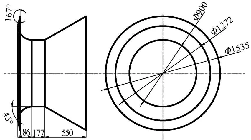
注:Φ为几何模型的截面直径,mm。
在研究过程中,采用四面体/混合非结构化网格对计算域进行分区域网格划分,浓缩风能装置内部的网格划分较密。在风速为10 m/s的平均来流条件下进行网格无关性分析,得到的流速与网格数之间的变化关系如图2所示。通过网格无关性分析,同时考虑划分网格设备配置和计算时间,确定划分网格尺寸得到计算域网格模型,计算域网格总数为7.27×106,网格模型如图3所示。
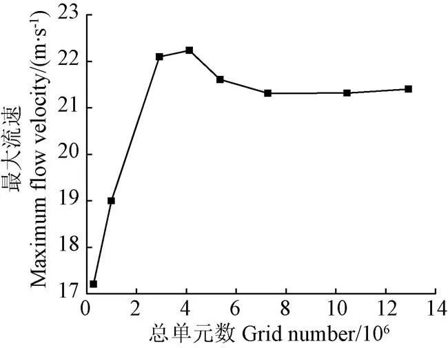
图2 不同网格数对应的流体最大流速
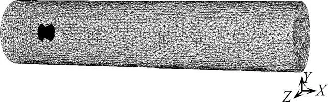
图3 浓缩风能装置网格模型
2.3 流场模拟条件设置
模拟过程中的流场流体介质为空气,密度为1.153 kg/m3[24]。
2.3.1 物理、数学模型
研究过程中忽略浓缩风能装置的壁面厚度和热量传递,将物理模型简化为非传热稳态不可压缩流体问题;数学模型则简化为连续性方程、Navier-stokes方程。
离散格式:二阶迎风格式。
压力-速度耦合:SIMPLE算法。
2.3.2 湍流模型
浓缩风能装置内部的流体流动属于壁面约束流动,存在边界层分离,而SST-湍流模型(剪切应力输运-湍流模型)在近壁面区域的计算精度与算法稳定性较高[25-27];且该湍流模型已在其他浓缩风能装置研究和风洞试验中得到充分应用,并验证了其计算结果的可靠性[28-29]。因此选用SST-湍流模型。
计算过程中使用能量方程,考虑热交换,
2.3.3 边界条件设置
由于将空气视为不可压缩流体,计算域边界条件设置为速度入口、压力出口,其他边界采用固定、无滑移的壁面条件。
2.4 浓缩风能装置扩散管凸缘模型
为提高浓缩风能装置的风能浓缩效率,优化浓缩风能装置流场性能,在原始浓缩风能装置(图1)的基础上增设扩散管凸缘,带有扩散管凸缘的浓缩风能装置几何模型(简称扩散管凸缘模型)如图4所示,运用CFD软件对扩散管凸缘高度由90 mm变化到450 mm、凸缘角度由−15°变化到+15°的各结构模型进行数值模拟计算,研究扩散管凸缘几何参数对浓缩风能装置流场性能的影响。
注:α为扩散管凸缘角度,(°);L为扩散管凸缘高度,mm。
3 模型验证
3.1 风洞试验内容与测试仪器
通过风洞试验研究分析所建浓缩风能装置模型的可靠性[24]。利用皮托管和多通道压力计分别测试浓缩风能装置内不同测试点处的总压(P)和静压(P),通过电脑控制多通道压力计进行数据采集,分析得出浓缩风能装置内部流场的流速变化规律。
测试仪器:皮托管、大气压计、温度计、多通道压力计和数据采集系统,电脑及配备的采集数据软件组成测试系统。风洞试验测试系统图如图5所示。
3.2 试验方法
首先进行风洞流场测试,选择一个合适的流场,在其内部固定浓缩风能装置模型,使模型的中心线位于风洞中心轴断面,多通道压力计和电脑等放置在控制室内并安装完毕;测试时标称风速取10 m/s,即试验过程中工作段入口附近截面中心的风速为10 m/s。风洞试验中的测试点分布如图6所示。
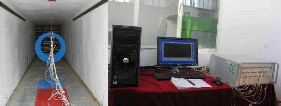
图5 风洞试验测试系统图
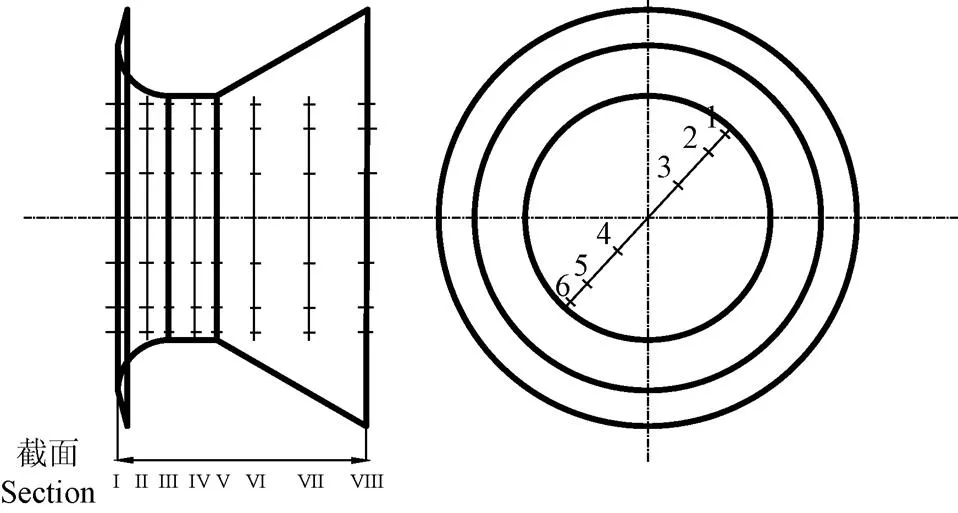
注:Ⅰ~Ⅷ为测试截面位置编号,1~6为每一测试截面上的测试点位置编号。
启动鼓风机,将其转速调试到之前流场测试时的频率,待流场稳定后,利用电脑控制多通道压力计进行数据采集。
3.3 试验结果与分析
根据风洞试验数据与在来流风速为10 m/s的模拟流场中计算得到的结果,可得8个测试截面上测试点流速沿径向分布如图7所示。
由图7可知,浓缩风能装置内8个截面上测试点流速的模拟计算结果大于试验所得数据,但流速沿径向变化的总体趋势基本相同;而测试截面I、VII和VIII上的模拟结果与试验结果差异较大,这是因为在风洞试验过程中浓缩风能装置的进口和出口处流体流动过程复杂,而模拟模型与试验模型相比,装置各部分之间均为光滑过渡连接,较为理想简化,使得流场内流体的流动情况无法在数值模拟中完整地体现出来;同时也存在现场试验数据测量、采集设备精度误差。
风洞试验过程中测得温度为−1 ℃,变化范围小于1 ℃。数据处理时取平均温度−1 ℃,平均大气压90 000 Pa,计算得统一空气密度为1.153 kg/m3。由温度变化引起的流体密度相对误差为−0.18%~0.18%,用统一空气密度进行数据处理得到的流体流速相对误差为−0.09%~0.09%[24]。
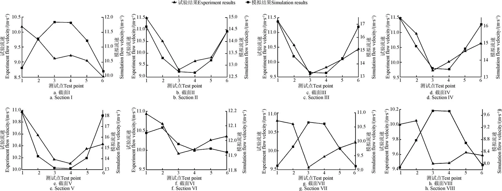
图7 模型内8个截面上测试点流速的径向分布
模拟计算过程中建立的计算域长度是浓缩风能装置模型长度的27.4倍,直径是装置模型最大截面直径的3.9倍,能够减少计算边界对计算结果的影响,并保证出口边界处流体不产生回流;在网格划分过程中对计算域进行分区域划分,并通过网格无关性分析确定了适合的网格模型,保证了计算结果精度[22,24];所采用的湍流模型SST-模型较为适用于壁面约束流动。Costin Ioan Coşoiu等[30]通过风洞试验验证了该种湍流模型用于浓缩风能装置周围的流场模拟研究准确度较高。
因此,数值模拟计算中所建立的浓缩风能装置模型能够保证模拟计算结果的可靠性,浓缩风能装置内部流场模拟结果是可靠的。
4 仿真结果与分析
4.1 扩散管凸缘对流场流速的影响
由图8可知,带有扩散管凸缘的浓缩风能装置模型内部流场的最大流速和沿轴最大流速矢量值均比原始模型有所提高;且扩散管凸缘模型内部流场的流速随凸缘高度的增加而增大,其中扩散管凸缘为450 mm、为−9°和+15°的浓缩风能装置模型内部流场流速较高:为450 mm、为−9°的模型内部流场最大流速为46.81 m/s,沿轴最大流速矢量值达到了45.62 m/s,分别比原始模型提高了33.943%和33.509%;为450 mm、为+15°的模型内部流场最大流速为46.79 m/s,沿轴流速矢量值达到了45.79 m/s,比原始模型分别提高了33.915%和34.006%。
扩散管凸缘分别为90、150、210、270、330、390和450 mm的模型内部流场流速随的变化趋势如图8所示。
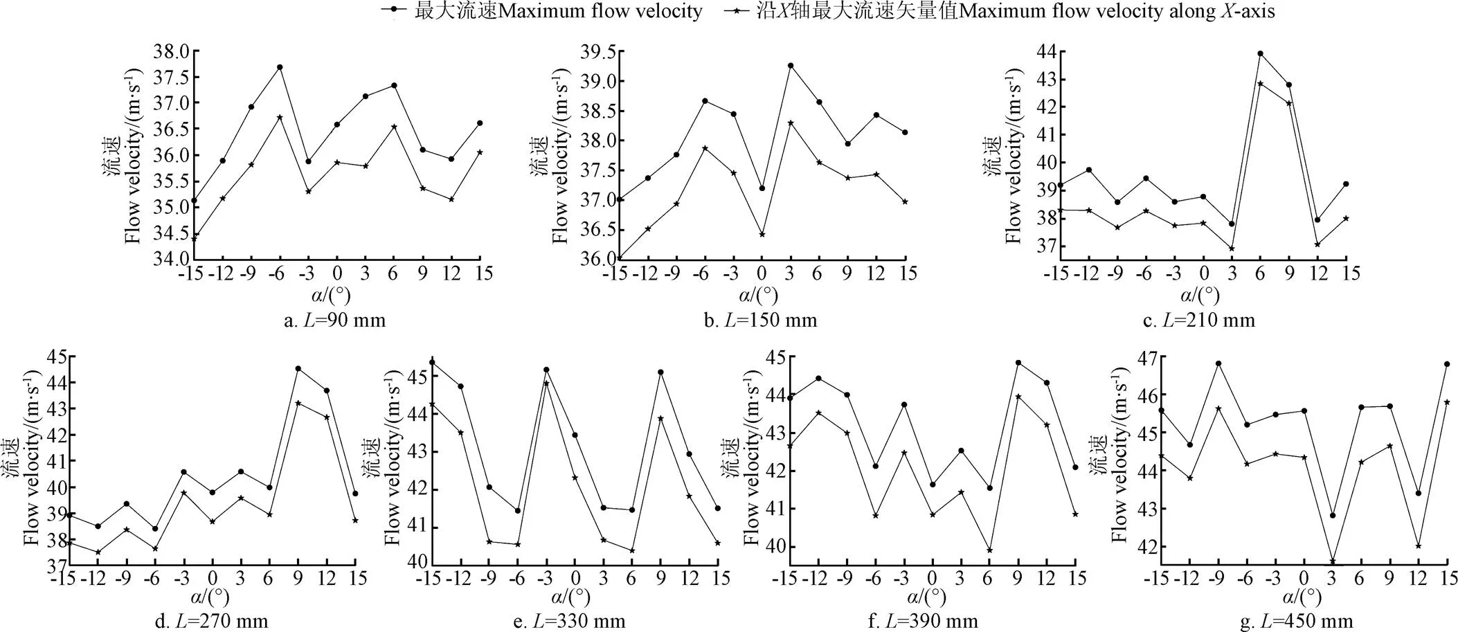
图8 扩散管凸缘模型内部流场流速随α的变化
由图8可知,扩散管凸缘为90和150 mm时,浓缩风能装置内部流场的最大流速和沿轴最大流速矢量值均在为−6°时相对较大;而当为210、270和390 mm时,为+9°的浓缩风能装置内部流体流速较大;为330 mm时,为−15°、−3°和+9°的模型内部流场的流体流速值较大,且与为450 mm相同的模型流速值相近,由图5b可知,为330 mm、为−3°的模型内部流场沿轴最大流速值(44.80 m/s)大于为450 mm、为−3°模型(44.43 m/s);当为450 mm时,流速较大值则出现在为−9°和+15°的模型结构中,其次是为−15°、−3°、+9°的模型内部流场流速较高。
通过分析带有不同几何参数的扩散管凸缘模型内部流场流体流速的模拟结果可得:扩散管凸缘模型内部流场的流速随的增加而增大;对于不同的扩散管凸缘,为+9°的浓缩风能装置内部流场流体的最大流速和沿轴最大流速矢量值较高,其中为450 mm的模型内部流场流速值较高,最大合流速和沿轴最大流速矢量值分别为45.68和44.64 m/s,比原始模型分别提高了30.738%和30.641%。
4.2 扩散管凸缘对机组可利用风能的影响
单位时间(1 s)内风电机组在风轮扫掠面积上的可利用风能可由式(1)计算得到。通过拟合浓缩风能装置风轮安装平面上流体流速在径向上的变化曲线得出流速随竖直高度变化的函数(),利用式(1)进行积分计算,由文献[3]可得原始模型能量利用效率为0.9355;不同凸缘高度的扩散管凸缘模型能量利用效率如表1所示。通过将积分结果分别乘以对应的能量利用效率,可得出不同几何参数的扩散管凸缘模型对应机组的可利用风能,结果如图9所示,风轮半径取0.4 m,且不加浓缩风能装置的机组可利用风能计算值为1.115 kJ,而加有浓缩风能装置原始模型(图1)的机组可利用风能计算值为2.789 kJ。
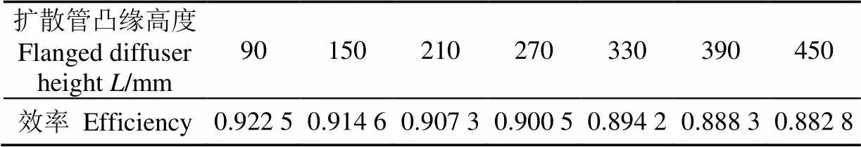
表1 扩散管凸缘模型能量利用效率
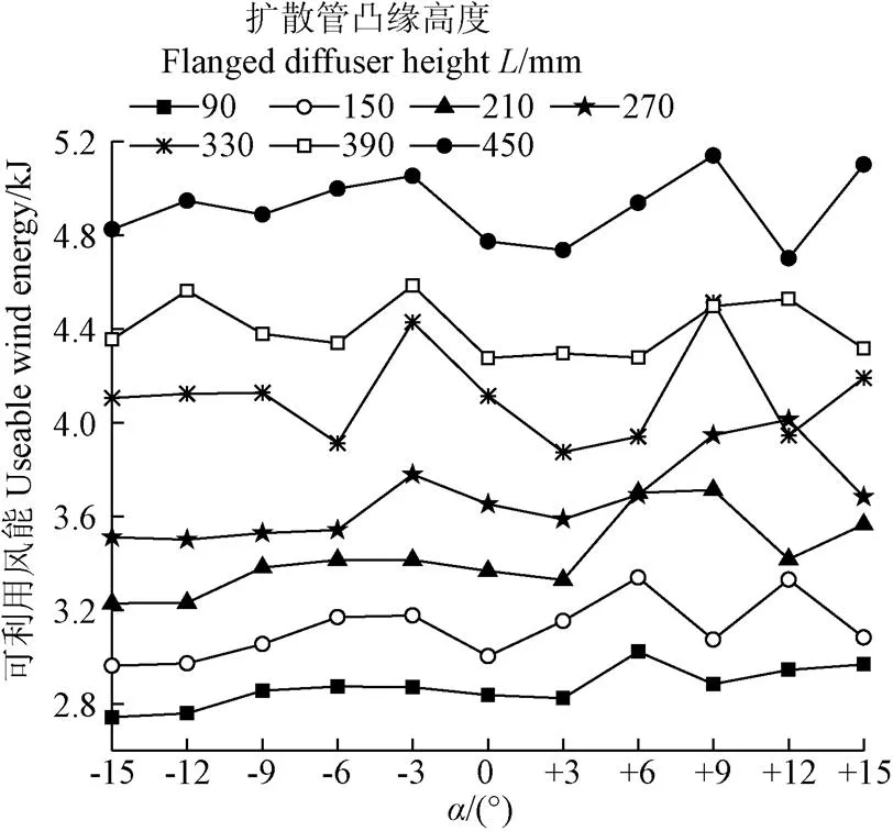
图9 不同几何参数的扩散管凸缘模型可利用风能
由图9可知,带有扩散管凸缘的浓缩风能装置对应的机组可利用风能计算值均高于原始模型(除为90 mm、为−15°和−12°的模型),说明扩散管凸缘能够提高浓缩风能装置的浓缩效率。而对于相同的浓缩风能装置模型,扩散管凸缘角度对机组可利用风能的影响较小,且的变化对机组可利用风能的影响程度随着的增大而增大。另外机组可利用风能的计算值随扩散管凸缘的增加而增大,在所研究模型中,为450 mm的浓缩风能装置对应机组的可利用风能较大,其中为450 mm、为+9°的扩散管凸缘模型对应的可利用风能最大,达到了5.139 kJ,比原始模型提高了84.26%。
通过研究分析扩散管凸缘几何参数对机组可利用风能的影响可得:可利用风能随扩散管凸缘的增加而增大,受变化的影响幅度与的大小成正比;在所研究模型中,扩散管凸缘为450 mm、为+9°的浓缩风能装置模型对风能的利用效率较高。
根据不同几何参数的扩散管凸缘对流场流速和机组可利用风能的影响研究结果,可进行如下分析:在所研究的模型中,为+9°的浓缩风能装置内部流场流体流速较高,说明凸缘为+9°的装置对自然风的加速效果较好,且其中为450 mm的模型内部流场流速较高;因此,扩散管凸缘为450 mm、为+9°的浓缩风能装置对应机组的可利用风能计算值较大,说明其浓缩风能效率较高。综上所述,从流场流速和机组可利用风能的角度分析,带有为450 mm、为+9°扩散管凸缘的浓缩风能装置模型是流场性能较佳的浓缩风能装置结构。
5 结 论
通过数值模拟与试验验证研究扩散管凸缘对浓缩风能装置流场性能的影响,得到结论如下:
1)扩散管凸缘结构能够明显提高浓缩风能装置对自然风的加速作用;装置内部流场的流速随凸缘高度的增加而增大,且为+9°的浓缩风能装置内部流场流体流速较高;其中为450 mm、为+9°的模型结构具有较好的聚风加速作用,其内部流场最大合流速和沿轴最大速度矢量值比原始模型分别提高了30.738%和30.641%。
2)扩散管凸缘结构能够明显提高浓缩风能装置对风能的全年利用率,而且工作段处风轮扫掠面积上的可利用风能随扩散管凸缘的增加而增大;在所研究模型中,为450 mm、为+9°的扩散管凸缘模型对应的机组可利用风能较大。
3)综合分析流场流速和机组可利用风能,带有为450 mm、为+9°的扩散管凸缘的浓缩风能装置模型流场性能较佳;并通过风洞试验验证了结果的可靠性。
[1] Stevens S J, Williams G J. The influence of inlet conditions on the performance of annular diffusers[J]. Journal of Fluids Engineering, 1980, 102(3): 357-363.
[2] Foreman K M, Gilbert B L. Experiments with a diffuser-augmented model wind turbine[J]. Energy Resource Techno Trans ASME, 1983, 105(3): 46-53.
[3] 田德. 大容量风力发电机组的设计[J]. 内蒙古农牧学院学报,1993,14(2):80-89.
Tian De. Design of large wind turbine[J]. Journal of Inner Mongolia Institute of Agriculture & Animal Husbandry, 1993, 14(2): 80-89. (in Chinese with English abstract)
[4] 田德,刁明光,黄顺成,等. 浓缩风能型风力发电机的整体模型风洞实验(第Ⅲ报):发电对比实验[J]. 农业工程学报,1996,12(2):92-96.
Tian De, Diao Mingguang, Huang Shuncheng, et al. A wind-tunnel test on the entirety model of concentrated wind energy turbine (Report No. 3): The generated output power comparative test[J]. Transactions of the Chinese Society of Agricultural Engineering (Transactions of the CSAE), 1996, 12(2): 92-96. (in Chinese with English abstract)
[5] Phillips D G, Richards P J, Flay R G J. CFD modelling and the development of the diffuser augmented wind turbine[J]. Wind and Structures, 2002, 5(2/3/4): 267-276.
[6] 韩巧丽,田德,王海宽,等. 浓缩风能型风力发电机相似模型流场特性实验:车载法实验与分析[J]. 农业工程学报,2007,23(1):110—115.
Han Qiaoli, Tian De, Wang Haikuan, et al. Test of flow field characteristics of the resembled model of concentrated wind energy turbine outside truck-mounted test and analysis[J]. Transactions of the Chinese Society of Agricultural Engineering (Transactions of the CSAE), 2007, 23(1): 110—115. (in Chinese with English abstract)
[7] 马广兴,田德,韩巧丽,等. 浓缩风能型风力发电机流场仿真与实验研究[J]. 内蒙古农业大学学报:自然科学版,2012,33(4):143—147.
Ma Guangxing, Tian De, Han Qiaoli, et al. Flow field simulation and experimental study on concentrated wind energy turbines[J]. Journal of Inner Mongolia Agricultural University: Nature Science Edition, 2012, 33(4): 143—147. (in Chinese with English abstract)
[8] 马广兴,田德,韩巧丽,等. 浓缩风能型风力发电机浓缩装置流场特性及试验[J]. 农业工程学报,2013,29(10):57-63.
Ma Guangxing, Tian De, Han Qiaoli, et al. Flow field characteristic and test on concentration device of concentrated wind energy turbine[J]. Transactions of the Chinese Society of Agricultural Engineering (Transactions of the CSAE), 2013, 29(10): 57-63. (in Chinese with English abstract)
[9] 汪建文,孙科,辛士宏,等. 风力机扩散放大器的数值分析与风洞实验研究[J]. 华中科技大学学报:自然与科学版,2005,33(12):37-40.
Wang Jianwen, Sun Ke, Xin Shihong, et al. The numerical simulation of inside flow field and wind tunnel experiment of diffuser augmented wind turbines[J]. Journal of Huazhong University of Science and Technology: Nature Science Edition, 2005, 33(12): 37-40. (in Chinese with English abstract)
[10] Abe K, Nishida M, Sakurai A, et al. Experimental and numerical investigations of flow fields behind a small wind turbine with a flanged diffuser[J]. Journal of Wind Engineering and Industrial Aerodynamics, 2005, 93(12): 951-970.
[11] 陈松利,田德,辛海升,等. 200 W浓缩风能型风力发电机的应用及运行效果[J]. 农业工程学报,2012,28(8):225-229.
Chen Songli, Tian De, Xin Haisheng, et al. Application and operation effect of 200W concentrated wind energy[J]. Transactions of the Chinese Society of Agricultural Engineering (Transactions of the CSAE), 2012, 28(8): 225—229. (in Chinese with English abstract)
[12] 韩巧丽,田德,王海宽,等. 浓缩风能型风力发电机改进模型流场与功率输出特性[J]. 农业工程学报,2009,25(3):93—97.
Han Qiaoli, Tian De, Wang Haikuan, et al. Flow field and power output characteristic of the reformative model concentrated wind energy turbine[J]. Transactions of the Chinese Society of Agricultural Engineering (Transactions of the CSAE), 2009, 25(3): 93-97. (in Chinese with English abstract)
[13] 宋海辉,田德. 浓缩风能型风力发电提水系统及其仿真研究[J]. 太阳能学报,2011,32(10):1556-1559.
Song Haihui, Tian De. Simulation research of the concentrated wind turbine water pumping system[J]. Acta Energiae Solaris Sinica, 2011, 32(10): 1556-1559. (in Chinese with English abstract)
[14] Chen T Y, Liao Y T, Cheng C C. Development of small wind turbines for moving vehicles: Effects of flanged diffusers on rotor performance[J]. Experimental Thermal and Fluid Science, 2012, 42: 136-142.
[15] 田德,姬忠涛. 聚碳酸酯材料的浓缩风能装置流固耦合分析[J]. 农业工程学报,2015,31(2):191-196.
Tian De, Ji Zhongtao. Fluid-solid interaction modeling analysis of wind-energy concentration devices with polycarbonate[J]. Transactions of the Chinese Society of Agricultural Engineering (Transactions of the CSAE), 2015, 31(2): 191-196. (in Chinese with English abstract)
[16] Wang W X, Matsubara T, Hu J, et al. Experimental investigation into the influence of the flanged diffuser on the dynamic behavior of CFRP blade of a shrouded wind turbine[J]. Renewable Energy, 2015, 78: 386-397.
[17] 田德,马广兴,林俊杰. 浓缩风能型风力发电机浓缩装置流场特性模拟与试验[J]. 农业工程学报,2016,32(15):83-88.
Tian De, Ma Guangxing, Lin Junjie. Simulation and experiment on flow field characteristics of concentrated device of concentrated wind energy turbines in wind shear[J]. Transactions of the Chinese Society of Agricultural Engineering (Transactions of the CSAE), 2016, 32(15): 83-88. (in Chinese with English abstract)
[18] Takagi S, Matsushima T, Muroyama S. Characteristics of a highly efficient propeller type wind turbine with a diffuser for stand-alone power supply systems[C] // INTELEC '03. Proceedings. The 25th International Telecommunications Energy-INTELEC '03, Japan, 2003: 391-395.
[19] Jafari S A H, Kosasih B. Flow analysis of shrouded small wind turbine with a simple frustum diffuser with computational fluid dynamics simulations[J]. Journal of Wind Engineering and Industrial Aerodynamics, 2014, 125: 102-110.
[20] Kosasih B, Hudin H S. Influence of inflow turbulence intensity on the performance of bare and diffuser-augmented micro wind turbine model[J]. Renewable Energy, 2016, 87: 154-167.
[21] Ohya Yuji, Karasudani Takashi. A shrouded wind turbine generating high output power with wind-lens technology[J]. Energies, 2010, 3(4): 634-649.
[22] 田德,毛晓娥,林俊杰,等. 浓缩风能装置内部流场仿真分析[J]. 农业工程学报,2016,32(1):104-111.
Tian De, Mao Xiao’e, Lin Junjie, et al. Internal flow field simulation of concentrated wind energy device[J]. Transactions of the Chinese Society of Agricultural Engineering (Transactions of the CSAE), 2016, 32(1): 104-111. (in Chinese with English abstract)
[23] 田德,王海宽,韩巧丽. 浓缩风能型风力发电机的研究与进展[J]. 农业工程学报,2003,19(增刊1):177-181.
Tian De, Wang Haikuan, Han Qiaoli. Study and development on the concentrated wind energy turbine[J]. Transactions of the Chinese Society of Agricultural Engineering (Transactions of the CSAE), 2003, 19(Supp.1): 177-181. (in Chinese with English abstract)
[24] 马广兴. 浓缩风能装置流场风切变特性实验研究[D]. 呼和浩特:内蒙古农业大学,2013.
Ma Guangxing. Experimental Study on Flow Field Characteristic of Concentrated Wind Energy Equipment in Wind Shear[D]. Hohhot: Inner Mongolia Agricultural University, 2013. (in Chinese with English abstract)
[25] Menter F R. Two-equation eddy-viscosity turbulence models for engineering applications[J]. AIAA Journal, 1994, 32(8): 1598-1605.
[26] Menter F R, Kuntz M, Langtry R. Ten Years of Industrial Experience with the SST Turbulence Model[C]//Turbulence, Heat and Mass Transfer, Antalya, Turkey, 2003.
[27] Tourlidakis A, Vafiadis K, Andrianopoulos V, et al. Aerodynamic design and analysis of a flanged diffuser augmented wind turbine[C]//ASME, San Antonio, USA, 2013.
[28] 林俊杰,田德,邓英. 浓缩风能装置流场仿真与优化设计[J]. 太阳能学报,2016,37(7):1891-1899.
Lin Junjie, Tian De, Deng Ying. Flow field simulation and optimization design of concentrated wind energy device[J]. Acta Energiae Solaris Sinica, 2016, 37(7): 1891-1899. (in Chinese with English abstract)
[29] 田德,林俊杰,邓英,等. 浓缩风能装置增压板流场性能仿真研究[J]. 太阳能学报,2017,38(1):39-46.
Tian De, Lin Junjie, Deng Ying, et al. Flow field performance simulation study on the pressurization board of concentrated wind energy device[J]. Acta Energiae Solaris Sinica, 2017, 38(1): 39-46. (in Chinese with English abstract)
[30] Costin Ioan Coşoiu, Andrei Mugur Georgescu, Mircea Degeratu, et al. Numerical predictions of the flow around a profiled casing equipped with passive flow control devices[J]. Journal of Wind Engineering and Industrial Aerodynamics, 2013, 114: 48-61.
Flow field simulation verification and flanged structure optimized design of concentrated wind energy device diffuser
Lin Junjie, Tian De※, Chen Jing, Wang Weilong, Deng Ying
(,,102206,)
Concentrated wind energy device is the core component of concentrated wind energy turbine, and the flanged diffuser can enhance the swabbing effect of the concentrated wind energy device, which can increase the flow velocity of internal flow field and improve the wind power quality consequently. To enhance the efficiency of the concentrated wind energy device, internal flow field characteristics of flanged diffuser models with different diameters (flange height ranging from 90 to 450 mm and angel from -15° to +15°) were simulated and analyzed. In the process of the numerical simulation, the fluid medium was the air with the temperature of 296.75 K and the density of 1.153 kg/m3. Besides, the velocity-inlet and pressure-outlet were adopted as the boundary condition of computational field. Other boundaries were set as stationary wall and no slip. The physical model was simplified to the steady incompressible fluid problem without heat transfer, and basic governing equations were continuity equations and Navier-Stokes equations. The turbulence model was SST (shear-stress transport)-model. Simulation results show that the flanged diffuser could strength the acceleration and concentration efficiency of concentrated wind energy device. And the flow velocity and usable wind energy of the rotor swept area were increased with the increasing of flange height. In all the models, when the flow velocity and usable wind energy were considered together, the model with flanged diffuser of height of 450 mm and angel of +9° was the optimal structure of concentrated wind energy device. Compared with the original model, the maximum flow velocity of the optimal model was increased by 30.738%, and the usable wind energy was increased by 84.26%. The feasibility of the model and simulation method were verified by wind tunnel experiment with the nominal wind speed of 10 m/s. Flow field calibration was proceeded in the wind tunnel firstly to choose a suitable flow field for the experiment. Then the concentrated wind energy device model, having the same scale with the numerical calculation model, was fixed at the selected location inside the wind tunnel and the center line was in the middle section of the tunnel. The total pressure and static pressure of different test points on radial direction inside the model were measured by the Pitot tube and multi-channel pressure gauge. The temperature recorded during the test fluctuated from -1 to -0.5 ℃ and the atmospheric pressure was from 899 to 900 hPa. Numerical calculation results were reasonably verified by wind tunnel experiments. Although numerical results were greater than the experimental data obtained with the model of the same size, the general trends were almost the same. The main reason of the difference between the results was that the numerical simulation model was too idealized to embody the complex flow conditions inside the model. All the conclusions obtained from the research can provide a basis for the structure optimization of concentrated wind energy device.
wind energy; flow field; numerical simulation; concentrated wind energy device; diffuser; flange
10.11975/j.issn.1002-6819.2017.18.008
TK83
A
1002-6819(2017)-18-0059-07
2017-04-14
2017-07-12
国家科技支撑计划资助项目(2009BAA22B02);中央高校基本科研业务费专项资金资助(2016XS56)
林俊杰,女,吉林辽源人,博士生,主要从事风力发电系统理论与技术研究。Email:linjunjie_1991@163.com
田德,男,吉林松原人,教授,博士生导师,主要从事风力发电系统理论与技术研究。Email:tdncepu@163.com
猜你喜欢
汽车实用技术(2022年19期)2022-10-19
小天使·五年级语数英综合(2021年9期)2021-09-18
辽宁师专学报(自然科学版)(2021年1期)2021-07-21
石油工程建设(2020年5期)2020-10-27
民用飞机设计与研究(2018年3期)2018-11-12
军事文摘·科学少年(2017年2期)2017-04-26
家教世界·创新阅读(2017年1期)2017-02-07
文理导航·科普童话(2016年3期)2016-04-26
汽车实用技术(2015年8期)2015-12-26
中国石油大学学报(自然科学版)(2015年2期)2015-11-10
