
Dynamic analysis of spinning solar sails at deployment process
2017-11-17 08:31XinxingZHANGChunyanZHOU
CHINESE JOURNAL OF AERONAUTICS 2017年5期
Xinxing ZHANG,Chunyan ZHOU
School of Aerospace Engineering,Beijing Institute of Technology,Beijing 100081,China
Dynamic analysis of spinning solar sails at deployment process
Xinxing ZHANG,Chunyan ZHOU*
School of Aerospace Engineering,Beijing Institute of Technology,Beijing 100081,China
The spinning deployment process of solar sails is analyzed in this study.A simplified model is established by considering the out-of-plane and in-plane motions of solar sails.The influences of structure parameters,initial conditions,and feedback control parameters are also analyzed.A method to build the geometric model of a solar sail is presented by analyzing the folding process of solar sails.Thefinite element model of solar sails is the n established,which contains continuous cables and sail membranes.The dynamics of the second-stage deployment of solar sails are simulated by using ABAQUS software.The influences of the rotational speed and out-of-plane movement of the hub are analyzed by different tip masses,initial velocities,and control parameters.Compared with the results from the oretical models,simulation results show good agreements.
1.Introduction
Solar sails have gained widespread attention for several decades because of the ir significant advantages,including small package volume,low energy consumption,and low cost.1–4The development of a solar sail spacecraft involves a wide range of technologies,and the manner in which to deploy a large area sail in space is a key design issue.5Among the proposed several deployment methods,the spinning deployment of solar sails is an ideal technique that utilizes centrifugal force to deploy sail membranes.6As a successful case,the Japan Aerospace Exploration Agency launched a spinningdeployable spacecraft named IKAROS on May 21,2010.7IKAROS succeeded in deploying a 20 m span solar sail from a wrapped status and managed to pass by Venus with the help of solar radiation pressure.8
Given the high flexibility of the membrane structure,rigorous control strategies must be used to avoid the entanglements or yo-yo-like oscillations caused by the repeated coiling and uncoiling of membranes to and from the hub.9–11Gardsback et al.12reviewed the existing control strategies for the centrifugal deployment of space webs.They concluded that stable deployment can be obtained by using the method of applying torque to the center hub,namely,the Melnikov–Koshelev law.10Gardsback and Tibert presented a simplified hubcable-mass model to qualitatively analyze the deployment dynamics in which out-of-plane motions were neglected.13Finite Element(FE)calculation using LSDYNA was proposed to simulate the dynamical response of the real deployment system.14Shirasawa et al.applied the Multi-Particle Method(MPM)to the dynamic analysis of IKAROS,and approximated the solar membrane by using the network of springs with lumped masses.15Haraguchi et al.used the model of MPM to validate the control laws for the spinning deployment of a solar sail system.16,17
A two-step deployment strategy was applied for the IKAROS.First,the four folded arms were slowly released from the tip by rotating the stopper relative to the hub.At the second stage,the four stoppers were released to deploy the entire membrane.A large disturbance at the beginning of the second-stage deployment was observed,which caused significant oscillations during the second-stage deployment.18Miyazaki et al.developed an FE model to analyze the nutation motion at firststage deployment.18,19Severe out-of-plane oscillations were also observed at the beginning of the second stage during the ground simulation tests conducted by Zhou et al.20
This study aims to analyze the deployment dynamics during the second stage under the initial perturbation of the instantaneous spreading out of the membrane.Following the work of Gardsback and Tibert13,a simplified hub-cable-mass model,including out-of-plane motion,is established to qualitatively analyze the effect of control parameters.An FE model of the solar sail is the n established.This model contains continuous cables and sail membranes.The second-stage deployment of a solar sail is simulated by using ABAQUS software.The influences of the rotational speed and out-of-plane movement of the hub are analyzed under different tip masses,initial velocities,and other factors.
2.Analytical model analysis
At the end offirst-stage deployment,the membrane arms togethe r with the center hub rotate stably with the same rotational speed.At the beginning of the second-stage deployment,the membrane is instantaneously deployed when the stopper is released.For the conservation of angular momentum,the rotational speed of the membrane becomes lower than that of the center hub,thus causing the in-plane oscillations of the system.When the membrane is spread from a zigzag folding pattern to a plane,out-of-plane motion is produced.To stabilize the deploying process,the system is controlled by applying a torque to the center hub with torque control law.This law implies that the torque increases when the hub angular velocity decreases and vice versa.To estimate the oscillations and control method,a simple analytical model is used to describe the deployment dynamics qualitatively.The development of our analytical model follows the model presented by Gardsback and Tibert.13The out-of-plane motions are included in our analytical model.The following assumptions are also made:

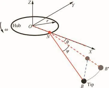
Fig.1 Analytical model for a point mass.
(1)The mass of the hub is higher than the sum of attached membrane,cable,and tip mass;hence,the hub is assumed fixed except its rational freedom in OZ axis.
(2)The motion of the membrane,cable,and tip mass is dominated by the cable and tip mass.The effect of membrane motion is equivalent to the additional mass at cable tip.
(3)Each part of the sail motion is the same(symmetric).
The analytical model is described in Fig.1.With the assumption of symmetric motion,only one part of the sail is considered for analysis.The entire sail consists offour parts.The coordinate system OXYZ is fixed with the center hub of the solar sail.In this model,the center hub is only free in its rotational motion by the OZ axis.The distancefrom the tip to the center hub edge is the length of the cable.This model can describe the relative position and motion of the center and sails by lengths,angles,and velocities.The system can be described by three degrees offreedom,the angular velocity of center hub ω,the relative in-plane rotational angle of the cable φ,and the out-of-plane rotational angle ψ.In this study,r is the hub radius and L is the cable length.
2.1.Equations of system dynamics
According to Lagrange’s law of motion,the dynamic equations of the system can be described as follows20:where g is the gravity coefficient for ground tests,which is zero on orbit;m is the equivalent mass of the membrane,cable,and tip mass system,and F is the tension force in the cable.The equivalent mass is determined by total inertial moment of the membrane,cable,and tip mass system.
During the deployment,an external moment M is applied to the center hub by the actuators that are installed on the hub edge.Accordingly,the hub dynamic equation can be described as

where J is the moment ofinertia of the center hub,M is a control torque,n is the number of cables.An appropriate M should be set to ensure successful and steady deployment.Several control strategies have been discussed.13One of the successful control laws involve increasing the torque applied to the hub as the hub angular velocity decreases;this approach was proposed by Melnikov and Koshelev for the deployment of the Znamya-2 reflector.10In our model,the external torque M applied to the hub is correlated with the error of the hub current angular velocity:

where k is the proportional gain,and ω*is the target hub rotational speed.
To analyze the effect of physical parameters on the dynamic response of the system,the non-dimensional parameters are introduced as follows:
Thus,the dynamics of this system are described as follows:

2.2.Results of numerical simulation
Numerical calculations are conducted to assess the effect of design parameters on the dynamic stability of the system,such as the torque and power requirements for the given deployment times with different masses and sizes of the hub and membrane.For the experimental system used by Zhou et al.20,the radius of the center hub is r=0.075 m,tip mass is m=0.02 kg,the moment ofinertia of the center hub is J=0.0281 kg·m2,the number offolded arms is n=4,the length of the cables is L=0.66 m,the center hub is controlled by a motor,the target rotational speed is set as ω*=20 rad/s,and the control gain is set as k=-0.06 N ·m ·s/rad.Thus,the non-dimensional parameters defined by Eq.(6)are=62.44,=8.8,and=-6.67.The dynamic response of the system can be calculated from Eqs.(7)–(10).
2.2.1.Effect of target hub rotational speed
~ω0denotes the ratio of the hub speed at the beginning of the second-stage deployment to that of the target speed at the end of deployment.Fig.2 shows the curves of the in-plane relative rotational anglewith four different initial angular velocityvalues.When=0.1,the angle parameter~φ increases unacceptably,and thus sails coil on the hub in the deployment process.Hence,target hub rotational speed lower than the initial speed should be considered for the control of the second-stage deployment.
2.2.2.Effect ofinitial relative rotational speed of membrane on that of hub
At the beginning of the second-stage deployment,as stopper is released,the membrane is instantaneously deployed.One of the aftereffects is that the rotational speed of the membrane becomes lower than that of center hub,which means a negative initial value of.Fig.3 shows the curves ofin-plane relative rotational anglewith four different initial values ofWhen the initialis as large as=-8,the membrane will become stable at=2π,thus entangling the whole system.Notably,when=-1,increases rapidly with time,and thus sails coil forward on the hub in the deployment process.Therefore,the initial in-plane relative rotational speed is important for system dynamics.Careful control parameters should be designed with a full consideration of the relative initial rotation caused by the sudden spread out of membrane.

Fig.2 Response of- under different values of=8.8,=-6.67=62.44=0,=-0.628=0.048=-0.314).
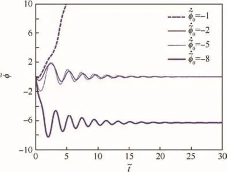
Fig.3 Response of under different values of=8.8,=-6.67,=62.44,=0.5,=0,=0.048,=-0.314).
2.2.3.Effect ofinitial out-of-plane angle
The other aftereffect of the sudden spread out of the membrane is small out-of-plane disturbance.Figs.4 and 5 show the curves of the in-plane and out-of-plane relative motions with three different initial values of.The results of stability analysis are confirmed by the calculation assumption that the out-of-plane motion has a small influence on in-plane motion and the torque control on the hub cannot damp out-of-plane motion.
3.Finite element analysis
The qualitative dynamic prediction of the deployment process can be studied by analyzing the analytical model,and an accurate prediction should be studied in the FE method.The interactions between four petals of membranes can be included by FE Analysis(FEA).
A 3D FE model including a center hub,membrane,cables,and four corner masses was implemented.The center hub was constrained to rotate around its center axis;hence,the center hub motion was one-dimensional.The geometry and connectivity of the node and element were generated in ABAQUS.The equations of motion were the n solved in ABAQUS by using the central-difference method for explicit time integration.The main differences compared with the analytical model are that the influence of the membrane motion can be studied with the FE model and that the cables are unnecessarily straight during the deployment.
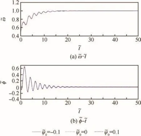
Fig.4 Response of- and- with different values of=8.8,=0.5,=62.44=0.5=0.5,=-0.628,=0.048).
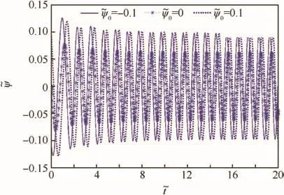
Fig.5 Response of with different values of=8.8,=0.5=62.44=0.5=0.5=-0.628=0.048).
3.1.Model setup for folded membrane
The accuracy of an FE model is strongly dependent on how well the modeled folded configuration coincides with the real one.A good geometry model must befirst obtained before the finite analysis of the deployment processes.As shown in Fig.6,a square plane OABC in plane OXY is folded to OA′B′C′.The constraints in the folding process are as follows:(A)Point A is in plane OXZ;(B)Point B is in plane X=Y;(C)Point C is in plane OYZ.
The relationship of angle θ and α can be expressed as follows:
According to the relationship of angle θ and α and the dimensions of plane OABC,the position offolded plane OA′B′can be obtained,which is shown in Fig.6.Position of the ith folding point in OXZ planeis determined by

Fig.6 Folding process of a square plane.

where Δl is the width of each folded strip.And position of the ith folding point in X=Z planeis determined by
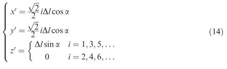
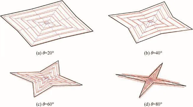
Fig.7 Folding process of solar sail model.
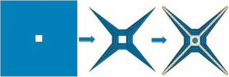
Fig.8 Establishment process of solar sail model.
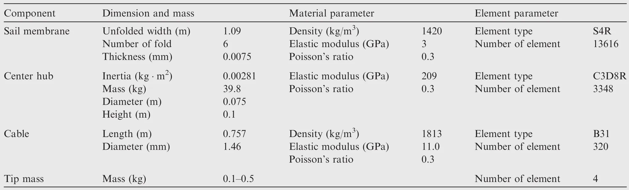
Table 1 Structural properties of solar sail model.

Fig.9 Comparison of experimental and simulation results for the second-stage deployment process.
By referring to several similar schemes of solar sail folded models8,9,a folding scheme is shown in Fig.7.

Fig.10 Curves of hub rotational speed for free deployment with different initial rotational speeds(tip mass=0.1 kg).
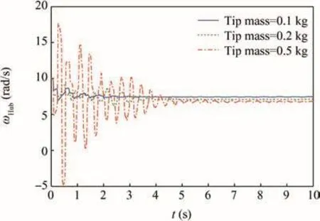
Fig.11 Curves of hub rotational speed for free deployment with different tip masses(ω0=10 rad/s).

Fig.12 Scheme of positions of tip masses.
According to the proposed fold scheme,a solar sail model is established,as shown in Fig.8.This model includes a center hub,cables,sail membranes,and tip masses.In this model,a cable is used to connect the sail membrane and center hub.Moreover,four tip masses are present and each of the m is located at the corner of the membrane.
This model is not folded completely and can be used to describe the initial status for the second-stage deployment.The center hub is modeled as a cylinder with rigid material,cables are modeled as beam element,and sail membrane is modeled as shell element.The details of the FE model are listed in Table 1.

Fig.13 Time history of φ1to φ4with various initial rotational speeds(tip mass=0.1 kg).
Simulations have been conducted by applying ABAQUS via the explicit integration method.During the analysis,the contact of each part is calculated by using the general contact method supported by ABAQUS.
An FEA model is established according to ground tests conducted by the same research group of the present study.20As shown in Fig.9,simulation results can simulate high comparability for the second-stage deployment process.
3.2.FEA results for free deployment without control
Contrary to the the oretical straight cable assumption,severe oscillations are observed because of the elastic retrieval and stretching of the cable with tip mass before the system becomes stable.For a 0.1 kg tip mass,Fig.10 shows the time history curves of the hub rotational speed with different initial rotational speeds at the end of first-stage deployment.Higher initial rotational speeds lead to higher vibrations.Fig.11 shows the time history curves of the hub rotational speed with different tip masses.The oscillations become more severe with heavier tip mass.
During the deployment process,the relative rotational angle of the membrane to the hub φ and out-of-plane motion angle ψ can be obtained by positioning the tip masses relative to the hub.Fig.12 shows the positions of four tip masses P1to P4.φ1to φ4are the relative rotational angles between the tip mass and the hub.Z1to Z4are the out-of-plane displacements of the four tip masses.
Figs.13 and 14 demonstrate the in-plane rotational angles φ1to φ4with various initial rotational speeds and various tip masses,respectively.Fig.15 shows the out-of-plane positions of the tip masses with various initial rotational speeds.Both the in-plane and out-of-plane vibrations increase with higher initial rotational angle and heavier tip masses because more elastic energy is stored in the cable.Because of gravitational acceleration,out-of-plane motion appears at the end of first stage.Small amplitude vibrations continue after the severe flexible vibrations of the cable damping off.However,for smaller initial rotational angle and lighter tip masses,the motions of the membrane lose synchronization because the motion of the system is dominated by unordered flexible waves in the membrane at low centrifugal forces.
Fig.16 demonstrates that out-of-plane vibration will not decay with time;this finding agrees with the analytical estimations in the previous section.Fig.16 shows out-of-plane vibration frequencies with various stable vibration speeds of the system ωstable.The out-of-plane vibration frequencies are near the stable vibration speed of the system ωstable;this finding also agrees with the theoretical estimation and experimental results.20
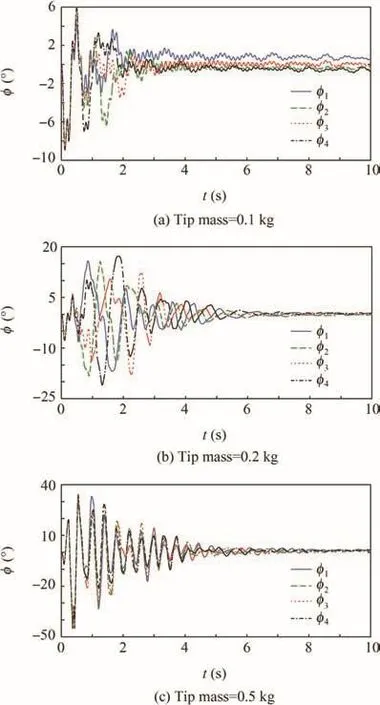
Fig.14 Time history of φ1to φ4with various tip masses(ω0=10 rad/s).
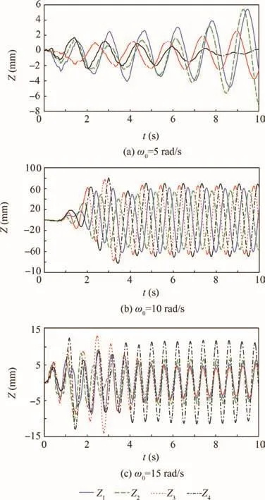
Fig.15 Time history of Z1to Z4with various initial rotational speeds(tip mass=0.2 kg).

Fig.16 Out-of-plane vibration frequencies vs stable vibration speed of system ωstable.
3.3.FEA results for deployment with control
To evaluate the effect of the control method proposed in Section 2,a torque is applied to the center hub with torque control law.This law implies that the torque increases when the hub angular velocity decreases and vice versa.This analysis is realized in ABAQUS with subprogram VUAMP.
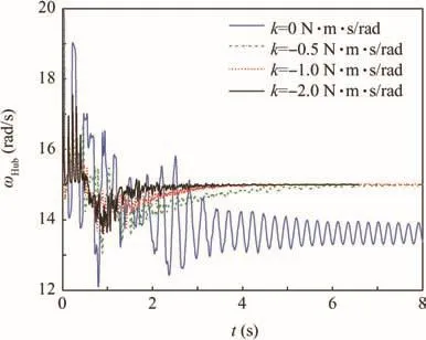
Fig.17 Time history of hub rotational speed with different control gains k(tip mass=0.2 kg,ω0=20 rad/s,ω*=15 rad/s).
A torque M=k(ω - ω*)is applied to the hub.Fig.17 shows the motion of a hub with different proportional gains k.Simulation results reveal that the in-plane vibration will continue for a long time if no control is applied.The in-plane vibration amplitude is lower with torque control.Furthermore,high proportional gains k indicate that the in-plane motion is suppressed quickly.
4.Conclusions and discussion
In this paper,a simplified model considering the out-of-plane motion of a solar sail is established to qualitatively analyze the dynamics of spinning solar sail at the second stage.The influences of structure parameters,initial conditions,and feedback control parameters are also analyzed to stabilize the deploying process.Theoretical analysis reveals that ratio of membrane size to hub size is important for ensuring successful deployment.An excessive size ratio will induce severe yo-yolike vibration in the system even with torque control.Moreover,a high ratio of membrane moment ofinertia to that of the hub may cause long in-plane vibration time even with torque control.For small initial perturbations,in-plane vibration may be ceased by the torque control applied to the hub,whereas out-of-plane vibration will succeed without a special damping strategy.Lower target rotational speed than the initial hub speed is preferred to obtain stable control.Notably,for finite initial in-plane relative rotation,the membrane may be secured to the hub with some combination of control parameters.
The second-stage deployment of the solar sail is simulated by using ABAQUS software.Thefolded configuration of the solar sail membrane model is established first,and dynamic simulations are conducted with explicit solutions.Severe vibration caused by the elastic flexibility of the cable system is observed.Non-synchronous motions of the four petals appear for small initial rotational speed and tip mass.
Interestingly,cables made of woven wire strands have small elastic flexibility,and this type is often used in the design of solar sail.The dynamic performance of the cable material may influence the dynamics of spinning solar sail deployment,which should be analyzed in future study.
Acknowledgments
This study was supported in part by the National Natural Science Foundation of China(Nos.11290151 and 51075032).
1.Catharine CF,Stoakley DM,Clair AK.Molecularly oriented films for space applications. High Perform Polym 1999;11(1):145–56.
2.Darooka DK,Jensen DW.Advanced space structure concepts and the ir development.Proceedings of the 42th AIAA/ASME/ASCE/AHS/ASC structures,structural dynamics,and materials conference and exhibit;2001 Apr.16–19;Seattle,USA.Reston:AIAA;2001.p.1257.
3.Hiroshi F,Makiko N,Satoshi M,Jodoi D,Terada Y,Takadamak K.Concept of inflatable tensegrity for large space structures.Proceedings of the 47th AIAA/ASME/ASCE/AHS/ASC structures,structural dynamics,and materials conference and exhibit;2006 May 1–4;Newport,Rhode Island.Reston:AIAA;2006.p.1700.
4.Nakasuka S,Aoki T,Ikeda I,Tsuda Y,Kawakatsu Y.‘Furoshiki satellite”—A large membrane structure as a novel space system.Acta Astronaut 2001;48(5–12):461–8.
5.Macdonald M.Advances in solar sailing.Chichester:Springer Praxis Books;2014.p.961-76.
6.Matunaga S,Yabe H,Nakaya K,Iai M,Omagari K,Mori O.Membrane deployment for spinning formation flight solar sail.Proceedings of the 14th ISAS/JAXA workshop on astrodynamics and flight mechanics;2004 July;Tokyo,Japan.Tokyo:Japan Aerospace Exploration Agency;2004.p.A-11.
7.Mori O,Sawada H,Funase R,Morimoto M,Endo T,Yamamoto T,et al.First solar power sail demonstration by IKAROS.Trans Japanese Soc Artif Intell,Aerospace Technol Japan 2011;8(27):425–31.
8.Tsuda Y,Mori O,Funase R,Sawada H,Yamamoto T,Saiki T,et al.Flight status of IKAROS deep space solar sail demonstrator.Acta Astronaut 2011;69(9):833–40.
9.Hedgepeth JM.Dynamics of a large spin-stiffened deployable paraboloidal antenna.J Spacecraft Rock 1970;7(9):1043–8.
10.Melnikov VM,Koshelev VA.Large space structures formed by centrifugal forces.1st ed.New York:CRC Press;1998.p.21–61.
11.Miyazaki Y,Iwai Y.Dynamics model of solar sail membrane.14th workshop on astrodynamics and flight mechanics;2004 Jul 26–27;Kanagawa,Japan.Tokyo:Institute of Space and Astronautical Science,Japan Aerospace Exploration Agency;2005.p.32–7.
12.Gardsback M,Tibert G,Izzo D.Design considerations and deployment simulations of spinning space webs.48th AIAA/ASME/ASCE/AHS/ASC structures,structuraldynamics,and materials conference;2007 Apr.23–26;Honolulu,Hawaii.Reston:AIAA;2007.p.1503–12.
13.Gardsback M,Tibert G.Deployment control of spinning space webs.J Guid Control Dynam 2009;32(1):40–50.
14.Gardsback M,Tibert G.Optimal deployment control of spinning space webs and membranes.J Guid Control Dynam 2009;32(5):1519–30.
15.Shirasawa Y,Mori O,Miyazaki Y,Miyazaki Y,Sakamoto H,Hasome M,et al.Analysis of membrane dynamics using multi-particle model for solar sail demonstrator ‘IKAROS”.Proceedings of the 52nd AIAA/ASME/ASCE/AHS/ASC structure,structural dynamics,and materials conference;2011 Apr.4–7;Denver,USA.Reston:AIAA;2011.p.1890.
16.Haraguchi D,Sakamoto H,Shirasawa Y,Mori O.Design criteria for spin deployment of gossamer structures considering nutation dynamics.Proceedings of AIAA guidance,navigation,and control conference;2010 Aug 2–5;Toronto,Canada.Reston:AIAA;2010.p.8072.
17.Sakamoto H,Shirasawa Y,Haraguchi D,Sawada H,Mori O.A spin up control schemefor contingency deployment of the sailcraft IKAROS.Proceedings of 52nd AIAA/ASME/ASCE/AHS/ASC structures,structural dynamics and materials conference;2011 Apr.4–7;Denver,USA.Reston:AIAA;2011.p.1892.
18.Sakamoto H,Miyazaki Y,Mori O.Transient dynamic analysis of gossamer-appendage deployment using nonlinear finite element method.J Spacecraft Rockets 2011;48(5):881–90.
19.Miyazaki Y,Shirasawa Y,Mori O,Sawada H.Finite element analysis of deployment of gossamer space structure.Proceedings of the ECCOMAS the matic conference on multibody dynamics 2011;2011 Jul 4–7;Brussels,Belgium.Melville:International Center for Numerical Methods in Engineering;2011.
20.Zhou XJ,Zhou CY,Zhang XX,Hu HY.Ground simulation tests of spinning deployment dynamics of a solar sail.J Vib Eng 2015;28(2):175–82[Chinese].
16 June 2016;revised 3 March 2017;accepted 25 May 2017
Available online 23 August 2017
Deployment;
Dynamics;
Solar sail;
Spinning;
Stability
*Corresponding author.
E-mail address:cyzhou@bit.edu.cn(C.ZHOU).
Peer review under responsibility of Editorial Committee of CJA.
Production and hosting by Elsevier
http://dx.doi.org/10.1016/j.cja.2017.08.006
1000-9361©2017 Production and hosting by Elsevier Ltd.on behalf of Chinese Society of Aeronautics and Astronautics.This is an open access article under the CC BY-NC-ND license(http://creativecommons.org/licenses/by-nc-nd/4.0/).
©2017 Production and hosting by Elsevier Ltd.on behalf of Chinese Society of Aeronautics and Astronautics.This is an open access article under the CC BY-NC-ND license(http://creativecommons.org/licenses/by-nc-nd/4.0/).
 CHINESE JOURNAL OF AERONAUTICS2017年5期
- CHINESE JOURNAL OF AERONAUTICS的其它文章
- Effect of an end plate on surface pressure distributions of two swept wings
- Determination of a suitable set of loss models for centrifugal compressor performance prediction
- Blade bowing eff ects on radial equilibrium ofinlet flow in axial compressor cascades
- A model offlow separation controlled by dielectric barrier discharge
- Research on parafoil stability using a rapid estimate model
- Transonic buff et control research with two types of shock control bump based on RAE2822 airfoil