
Drag derived altitude aided navigation method
2017-11-17 08:31HuSONGMeilingWANGJingYANGDntongSUNLongtoKONGChunlingWEI
CHINESE JOURNAL OF AERONAUTICS 2017年5期
Hu SONG,Meiling WANG,Jing YANG,*,Dntong SUN,Longto KONG,Chunling WEI
aSchool of Automation Science and Electrical Engineering,Beihang University,Beijing 100083,China
bCollaborative Innovation Center of Advanced Aero-Engine,Beihang University,Beijing 100083,China
cNational Key Laboratory of Space Intelligent Control Technology,Beijing 100094,China
Drag derived altitude aided navigation method
Hua SONGa,b,Meiling WANGa,Jing YANGa,*,Dantong SUNa,Longtao KONGa,Chunling WEIc
aSchool of Automation Science and Electrical Engineering,Beihang University,Beijing 100083,China
bCollaborative Innovation Center of Advanced Aero-Engine,Beihang University,Beijing 100083,China
cNational Key Laboratory of Space Intelligent Control Technology,Beijing 100094,China
The navigation problem of the lifting reentry vehicles has attracted much research interest in the past decade.This paper researches the navigation in the blackout zone during the reentry phase of the aircraft,when the communication signals are attenuated and even interrupted by the blackout zone.However,when calculating altitude,a pure classic inertial navigation algorithm appears imprecise and divergent.In order to obtain a more precise aircraft altitude,this paper applies an integrated navigation method based on inertial navigation algorithms,which uses drag derived altitude to aid the inertial navigation during the blackout zone.This method can overcome the shortcomings of the inertial navigation system and improve the navigation accuracy.To furthe r improve the navigation accuracy,the applicable condition and the main error factors,such as the atmospheric coefficient error and drag coefficient error are analyzed in detail.Then the damping circuit design of the navigation control system and the damping coefficients determination is introduced.The feasibility of the method is verified by the typical reentry trajectory simulation,and the influence of the iterative times on the accuracy is analyzed.Simulation results show that iterative three times achieves the best effect.
1.Introduction
Owing to the characteristics of the rocket,spacecraft,reentry vehicle and aircraft,the lifting reentry vehicle has been widely used in the field of space technology,and the navigation problem of the reentry vehicle has been getting more and more attention.1,2The reentry flight is characterized as high speed,large attack angle,large aerodynamic interference,and the existence of the phenomenon of blackout zone.3,4According to the characteristics of the reentry flight and autonomous navigation,the main reentry vehicle navigation is Inertial Navigation System(INS)/Global Positioning System(GPS)/Celestial Navigation System(CNS)integrated navigation at present.5,6
When the reentry vehicle returns to the atmosphere at a high speed,the ground communication will be interrupted in a certain altitude area,and the area is called blackout zone.7,8The blackout zone occurred between 35 km and 80 km over the Earth’s atmosphere,and when the reentry vehicle is in the blackout zone,the temperature of the vehicle hulls will reach 2000°C,hence the GPS,radio navigation and communication will be interrupted,and the n the reentry vehicle losses external contact(high temperature ionizes the air around the aircraft into plasma,and the n shields the electromagnetic wave).Thus the groundings cannot obtain the information of the shuttle’s real-time condition.9–12At this point,the navigation of reentry vehicle can only rely on inertial navigation,a kind ofindependent navigation technology that does not rely on external signals.But due to the defect of INS,relying on pure inertial navigation willlead to large navigation errors.So when the vehicle returns,the blackout phenomenon makes real time communication and measurement rathe r hard.
In view of the problem of blackout phenomenon,Ref.8introduced several methods,such as changing the shape design of reentry vehicle,adding an external magnetic field to weaken the influence of the blackout zone.But with the se methods,the aircraft structure or flight environment needs changing,the implementation is difficult and of high cost.13Some researches use only INS for the aircraft navigation during the blackout zone,14,15which employs inertial navigation system directly to calculate the altitude of the aircraft and proves to have a large error.In Refs.5,6,the GPS’s prediction information is used for the vehicle navigation during the blackout zone,but the uncertainty of the prediction information will affect the navigation accuracy.So in order to ensure the navigation accuracy when the aircraft is out of the blackout zone,it is necessary to use auxiliary method to restrain the divergence of INS.The Refs.16,17proposed a combined navigation method which uses Drag Derived Altitude(DDA)aided inertial navigation system to the reentry vehicle navigation in the blackout zone. The nongravitational acceleration of the reentry vehicle,and the aerodynamic and atmospheric models are used to estimate the altitude of the craft in DDA.And using DDA is able to get a higher accuracy than a pure classic inertial navigation algorithm.But the main error factors of DDA and the damping circuit design of the integrated navigation control system has not been introduced in detail in the two articles.
This paper mainly discusses the navigation method during the blackout zone.Firstly it introduces the principle of DDA measurement and the solution of the parameters used,the n a two order damping loop is established to combine the altitude of DDA with the inertial navigation information.Next,this paper analyses the applicable condition,the main error factors and the effect of the iterative times in detail.And at last,the integrated navigation method is applied to the navigation of the reentry vehicle during the blackout zone and the feasibility of this method is verified by simulation results.

2.Drag derived altitude
2.1.Definition of coordinate systems
(1)Earth-Centered Inertial(ECI)coordinate system
The inertial coordinate system of Earth defines a coordinate which is fixed with the rotating Earth and whose origin Oiis at Earth center.The principal direction xiis through the equatorial at RAAN(Right Ascension of the plane Ascending Node of the orbit),ziis through the Earth’s rotation axis to north and yicompletes the right-handed system.
(2)Earth-Centered Earth-Fixed(ECEF)coordinate system
A coordinate system whose origin Oeis at the center of the Earth and axis xeis through the equatorial at Greenwich,yeis through the equatorial and is perpendicular to xe,and zecompletes the right-handed system.
(3)Body coordinate system
A coordinate system whose origin Obis at the aircraft center and axes move with the aircraft.The xbis typically aligned with body spin axis and points to the head of the aircraft,and the ybis perpendicular to xband points to the top of the aircraft,and zbcompletes the right-handed system.
(4)Navigation coordinate system
Navigation coordinate system(Onxnynzn)is the same as the Earth-centered inertial coordinate system in this paper.
(5)Speed coordinate system
A coordinate system whose origin Obis at the aircraft center and whose axes move with the aircraft.The xvis along the direction of the speed,the yvis in the longitudinal symmetry plane of the aircraft and perpendicular to xvand points to the top of the aircraft,and the zvcompletes the right-handed system.
The transformation between different coordinate systems are usually defined as the form of C21,which means the transformation matrix from 1 coordinate system to 2 coordinate system.And the transformation between different coordinate systems are given as follows:
(A)Navigation coordinate system and body coordinate system
The transformation matrix can be acquired by rotating the navigation coordinate system three times to the body coordinate system z(θ)→ y(ψ)→ x(γ).The transformation matrix is where θ,ψ and γ are respectively pitch angle,heading angle and roll angle of the aircraft.
(B)Speed coordinate system and body coordinate system
According to the definition,the Obyvaxis of the speed coordinate system is in longitudinal symmetry plane of the aircraft,that is the xbObybplane of the body coordinate system.Therefore,the conversion between the two coordinate systems only exists two Euler angles,and the body coordinate system can be acquired by the body coordinate system rotating two times:y(β)→ z(α),and the transformation matrix is

where α is the angle of the attack,the angle between the velocity vector projection in the main symmetry plane of the aircraft and the longitudinal axis of the body,which selects the downward direction as positive direction.β is the sideslip angle,which is the angle between the velocity vector and the main symmetry plane of the aircraft,which chooses the right direction of the main symmetry plane as positive direction.
2.2.DDA principle
DDA is a pseudo-measurement of the altitude obtained from aerodynamic model,atmospheric model and the estimated non-gravitational acceleration.When flying without other external forces,the aircraft is subjected to the gravity and aerodynamic force.The aerodynamic force can be decomposed into drag and lift.And the force analysis of the aircraft is shown in Fig.1,where P is the push along the longitudinal axis of the aircraft and pointing to the front,G is the Earth gravity,pointing to the center of the Earth center,D is the drag along the opposite direction of the movement,L is the lift,perpendicular the motion direction and pointing upward.Mris the rolling moment,and Vris the aircraft velocity.
By the the ory of aerodynamics,the air drag is

where ρ is the local atmospheric density,Srefis the atmospheric reentry aircraft referential area,and CDis the drag coefficient.
According to Newton’s second law:


Fig.1 Force analysis of aircraft.
where m is the aircraft mass,Γ is the acceleration produced by air drag,which can be obtained by accelerometers.
According to Eqs.(3)and(4),the non-gravitational acceleration along the velocity in the opposite direction is:

Assume that the atmospheric density evolution is locally exponential,the n the atmospheric density model is given as:

where h is the altitude,H(h)is the local atmospheric coefficient,and ρ0is the sea level atmospheric density.According to Eqs.(5)and(6),the ‘pseudo-measurement” of the altitude h can be derived by

2.3.Altitude calculation method using DDA combined with INS
It is clear that the local atmospheric coefficient H(h)and the drag coefficient CDare the key to solving Eq.(7),and other parameters can be obtained from aircraft parameters and accelerometers.
(1)Atmospheric coefficient H(h)calculation
Velocity and position information provided by INS can help to calculate the local atmospheric coefficient,and provide the relative velocity.In order to obtain the local atmospheric coefficient,it is necessary to convert the position information Xp(t)of INS output to the altitude h.
Then the local atmospheric coefficient H(h)can be acquired by using the estimated altitude h to look up the atmosphere model table.
(2)Relative velocity Vrcalculation
Relative velocity,the modulus of the aircraft velocity,can be calculated according to the three axis velocity in navigation coordinate,

where Vn= [Vnx,Vny,Vnz]is the triaxial velocity component of aircraft obtained by INS in the navigation frame.
(3)Drag coefficient CDcalculation
Drag coefficient is determined by the velocity and angle of attack.This paper uses Mach number Ma=Vr/Vsoundto represent speed,where Vsound=340 m/s.
The blackout zone occurred between 35 km and 80 km over the Earth’s atmosphere,and this altitude ranges from stratosphere to mesosphere.In stratosphere,wind speed is generally tens of meters per second,18and this velocity is very small relative to reentry vehicle velocity.Therefore,wind speed can be ignored when calculating the angle of attack during the blackout zone.
When the re is no wind,the ground velocity is equal to the relative air velocity,the n the angle of attack and sideslip angle can be calculated by using the ground velocity.Converting the velocity vector Vninto the body system, we get Vb=CbnVn= [Vbx,Vby,Vbz]T.Thus α and β can be assessed by

Then,using Mach number and attack angle we get drag coefficient according to the aerodynamic model.Since it is hard to establish the aerodynamic model analytic equation,the drag coefficient is obtained by looking-up table method in this paper.
(4)Non-gravitational acceleration calculation
According to the force analysis in Fig.1,the output of aircraft accelerometer is determined by the resultant force except gravity.Since the re is only air drag along the velocity direction except gravity,the acceleration Γ produced by the air drag is the projection of resultant acceleration in the opposite direction of velocity.Converting the accelerometer output from the body system to the speed system Obxvyvzv,the component along the opposite direction of x axis is Γ.
According to the above analysis,a ‘pseudo-measureme nt”of the altitude is available,and the process is shown in Fig.2,whereis the angular velocity of the b coordinate system relative to the i coordinate system projected in the b coordinate system,is the specific force of the b coordinate system relative to the i coordinate system projected in the b coordinate system,is the specific force of the v coordinate system relative to the i coordinate system projected in the v coordinate system,Xp(t)and Vn(t)are the position and velocity information calculated by the INS respectively.

Fig.2 Calculation process of DDA.
3.Referential height aided INS navigation method
3.1.INS divergence mechanism
In the inertial coordinate system,the three channels of INS are divergent.So without auxiliary information,the altitude calculated by INS would have a great error during the blackout zone.The reasons are analyzed as follows.
3.1.1.INS solution process
In the inertial system,the inertial navigation system is mainly divided into three steps:attitude update,position update and speed update.
(1)Attitude update
The update equation of attitude matrix is

(2)Speed update
The velocity differential equation in the inertial system is

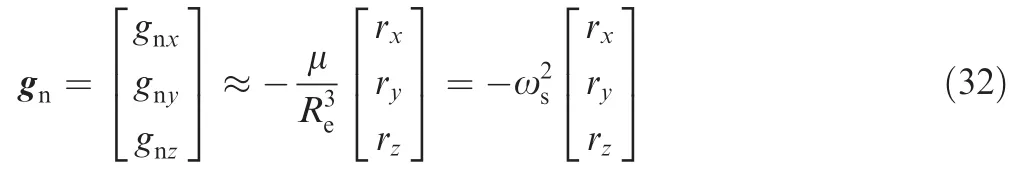
wherefbis the specific force measured by accelerometer;gnis gravitational acceleration in the inertial coordinate system,and its calculation formula is

where rx,ry,rzare the location coordinates of aircraft in inertialsystem,and ris the geocentric distance,thatisμ is the product of the Earth’s mass and gravitational constant,Reis the radius of the Earth’s equator,and J2is the perturbation term.Different referential ellipsoid models use different Earth parameters,and the constants used in this scheme are μ =3.986035 × 10¹⁴m3/s2,Re=6378140 m and J2=1.08230×10⁻³.
(3)Position update
The position differential equation in the inertial coordinate system is

where rn= [rx,ry,rz]Tis the position vector of aircraft in inertial coordinate system.
3.1.2.Error propagation equation of INS
The error propagation equation is derived based on the INS mechanics.
(1)Propagation equation of attitude misalignment angle
The error angle between the ma the matical platform^n simulated by INS and the ideal navigation coordinate system n is defined as the attitude misalignment angle, that is φ = [φx,φy,φz]T,where φ is small.Then n can be obtained by^n through the following equation:

where [φ×]is anti-symmetric matrix of φ,that is


Bring Eqs.(10)–(16),the n

According to Eq.(10),the partial differential equation of

Compare Eqs.(17)and(18),it is obvious that

According to [(AB)×]=A[B×]AT,where A is an orthogonal matrix,B is a column vector.Then

This is the propagation equation of attitude misalignment angle,whereis the error of angular velocity.It can be seen that the platform drift of inertial coordinate system is caused by the measurement error of the gyroscope totally.
(2)Propagation equation of velocity error
According to Eq.(11),the partial differential equation of

Eq.(22)is the speed error propagation equation,where δVn= [δVnx,δVny,δVnz]T, [fn×] isanti-symmetric matrix formed by the projection component of accelerometer output in navigation system,that is fn=Cnbfb.δfbis the measurement error of acceleration,δgnis the projection of gravitational acceleration error in the navigation coordinate system caused by the position error and can be obtained by the differential calculation of gn.
(3)Propagation equation of position error
The propagation characteristics of position error is relatively simple,with the expression as

where δrn= [δrx,δry,δrz]T.
According to the error propagation equation,the reason why the three channels are divergent is explained as follows.From Eq.(7)when the disturbance item J2is neglected,the calculation formula of gravitational acceleration can be simplified as follows:

So the differential equation of gravitational acceleration is changed to

where

Therefore,assume the position error and velocity error in the inertial coordinate system as the state variable,the nAccording to Eqs.(22),(23)and(25),X can be explained as

where the second item at the right side of the formula is irrelevant to position error and velocity error.The system characteristic equation is
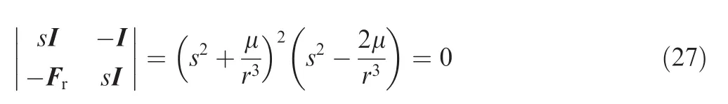
Thus, the characteristic roots are
It is clear that the system contains Schuler oscillation period components,and because the characteristic roots contain positive real part,the position errors of three channels in INS are exponentially divergent in the inertial navigation system.
3.2.Damping loop design and damping coefficient determination
The navigation error of INS is divergent during the process of reentry section without other information supporting.Therefore,it is necessary to introduce auxiliary information,such as altitude calculated from DDA.Because the damping is realized in the inertial coordinate system at three channels respectively,three dimensional position vectors used in the damping loop is calculated by using the referential height which can be obtained by DDA,and the longitude and latitude obtained by INS.
The damping loop is designed based on the control the ory.In the original inertial navigation loop,the damping loop is added to change the stability of the system to achieve the purpose of restraining error accumulation and improving navigation accuracy.In this paper,the second-order damping circuit with high accuracy and less damping parameters is designed.The structure is shown in Fig.3.
The two integral parts of the forward channel are the pure INS and the damping coefficient of the three channels respec-
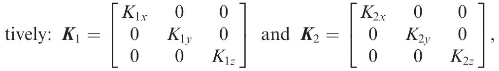
within which K1x,K2xare the damping coefficients of x axis,K1y,K2yare the damping coefficients of y axis and K1z,K2zare the damping coefficients of z axis.hrefis auxiliary referential height,and the part in the dotted borders converts the onedimensional height information(^h),longitude(^λ)and the latitude(^L)into a three-dimensional position vector rn,ref.The auxiliary height hrefin the blackout zone is provided by DDA.AccordingtoFig.3,the system differential equations of position and velocity with the second-order damping are given as follows:

According to Eqs.(22),(28)and(29),after employing the second-order damping loop,the position and velocity error propagation equations of the INS are as follows

where δrn,refis the position error vector derived by the auxiliary height information,and δrn,refis related to the INS error and the auxiliary height.The propagation equation of the attitude misalignment angle will not change when the damping is added.
According to Eq.(24),assume that the aircraft altitude h≪Re,the n r≈Re,Eq.(24)can be further simplified as
Then the differential calculation formula of gravitational acceleration is

bringing Eq.(33)to Eq.(31),the n


The system characteristic equation is

The damping coefficient is solved by pole placement method in this paper,where six identical negative poles are assigned,and can ensure the stability of the system.The poles of the damping system are assigned as:

where τ is time constant reflecting the regulation time and overshoot of the system.From Eqs.(36)and(37),the damping coefficient K1and K2can be calculated.In order to simplify the design of the parameters,assume the damping coefficients are the same,that is K1x=K1y=K1z=K1,K2x=K2y=K2z=K2.K1and K2can be calculated according to control principle,and

Fig.3 Structure diagram of INS with a second-order damping circuit.
4.Analysis of DDA simulation
4.1.Analysis and processing of original data
The atmospheric model and air drag coefficient model are given in Tables A1 and A2(see Appendix A).The corresponding parameters are obtained by looking up tables.The table of atmospheric model is given by the table of h- ρ(h),while h-H(h)is required by Eq.(7)to obtain h.According to Eq.(6),one can get H(h)=-ln(ρ/ρ0)/h,and the table h- ρ(h)can be transferred to the form of h-H(h).In simulation,according to the altitude calculated by INS,the corresponding atmospheric coefficient is obtained by checking h-H(h)table and carrying on a linear interpolation.
The drag coefficient is associated with the Mach number and the angle of attack. A two-dimensional table(Ma,α)-CDis obtained by experiments,the n CDcan be obtained by the two-dimensional table looking up and the bilinear interpolation according to the speed and attack angles.If the velocity or the angle of attack is beyond the scope of the table,the boundary value is used to replace the velocity or the angle of attack.
During the reentry process,the aircraft is only affected by the Earth gravity and the air force,so Γ is the projection of the acceleration vector in the velocity reverse direction and Vris the speed of the aircraft relative to the air,that is,the value of the vehicle speed.The other variables of DDA are the parameters of the aircraft itself.
4.2.Simulation of DDA under ideal input
Using the ideal height and acceleration as input,the altitude error of DDA during the whole reentry process is calculated.Then the altitude error is shown in Fig.4(as the altitude of the reentry vehicle decreases monotonically during the whole reentry process,the aircraft height is selected as the abscissa.In this paper,the analysis of DDA is simulated in the blackout zone,and the altitude is 35–90 km).

Fig.4 Altitude error of DDA.
It is shown that the accuracy of DDA is the best when the real height is between 20 and 90 km,because at lower altitudes the wind speed has a relatively large effect on the reentry aircraft speed,and at higher altitudes,no significant acceleration produced by residence can be established,so the accuracy of DDA is relatively low.
In addition,it is clear in Fig.4 that the altitude calculated by DDA in 35–90 km is lower than the actual height,because the re is a constant deviation when using interpolation algorithm to calculate.To furthe r improve the accuracy,the more precise atmospheric model and aerodynamic coefficient model is needed.
The change regularity of the air density is very complex,and several main factors affecting the density change are:height,the shape of the Earth,the seasons and so on.19,20The reentry environment is also very complex,the drag coefficient of reentry aircraft is affected by angle of attack,Mach number,atmospheric density and rudder angle and so on.Thus,for more accurate atmospheric density models,it is necessary to fully considerate the factors that affect the atmospheric density and aerodynamic coefficient to establish mathematical models.
4.3.Error analysis of DDA
The basic principleformula of DDA is given as Eq.(7),the accuracy of the aircraft velocity Vr,the atmospheric coefficient H,the acceleration Γ,the drag coefficient CDare the main factors that affect the DDA accuracy.Assume that ΔH,ΔVr,ΔCDand ΔΓ are the maximum errors on H,Vr,CDand Γ,and the se errors may be caused by the reasons shown in Table 1.
Among the above reasons,the error analysis of the inertial navigation errors,the INS accuracy can be unified as the error analysis ofinertial navigation.The atmospheric model and the drag coefficient model are based on the method of looking up tables which has certain uncertainty.The wind and the Earth model mainly affect the drag coefficient and the air coefficient,the y are attributed to the model error in this paper.
4.3.1.Error analysis of INS
The errors considered in simulation are as follows:
(1)Installation deviation of INS is 90′.
(2)Initial position error is 200 m,initial velocity error is 0.5 m/s,and initial pose error is 720′.
(3)The nonorthogonal installation deviation of gyro is 90′,and the constant drift is 0.1°/h.
(4)The nonorthogonal installation deviation of accelerometer is 90′,and the constant drift is 10-4g,where g is the gravity acceleration.

Table 1 Errors causes.
(5)Standard error of gyro scalefactor is 1 × 10⁻⁴(3σ),standard deviation of random noise is 1.4142°/h,where σ is the standard deviation.
(6)Standard error of accelerometer scale factor is 2 × 10⁻⁴(3σ),standard deviation of random noise is 10-4g(3σ).
In this paper,for the convenience of expression,we use INS installation error,gyro error,and accelerometer error to express the errors considered in simulation.The specific expression is shown in Table 2.
The error of DDA considering different conditions is shown in Fig.5.Fig.5(a)is the DDA error when the INS installation error and initial altitude error are considered;Fig.5(b)is the DDA error when the INS installation error,initial attitude error and gyro error are considered;Fig.5(c)is the DDA error when the INS installation error,initial attitude error and accelerometer error are considered,and Fig.5(d)is the DDA error when the INS installation error,initial attitude error,gyro error and accelerometer error are considered.
Fig.6 is the comparison chart of the DDA height errors in the following cases:no error,the INS error only,INS error and gyro error,INS error and accelerometer error,and including the se three kinds of errors.Fig.7 is the comparison chart of the DDA height errors adding different size errors to the gyro.And Fig.8 is the comparison chart of the DDA height errors adding different size errors to the accelerometers.In Figs.7 and 8,the errors added are shown in Table 3.
It can be shown from Fig.5 that the influence of the INS installation error and initial attitude error is not very large.Fig.6 shows the effect of gyros error and accelerometers error on the DDA error;Fig.7 shows that the effect of gyro error on the DDA error is about 200 m;Fig.8 shows that the effect of the accelerometer error on the DDA error is about 200 m.
4.3.2.Error analysis of atmospheric coefficient error ΔH
The atmospheric coefficient will directly affect the accuracy of DDA.The atmospheric model is influenced by altitude,Earth rotation,wind,shape of the Earth and seasons.It is difficult to establish a precise atmospheric model to determine the atmospheric density.This paper uses the method of adding devia-tion to the true value of atmospheric coefficient,and the deviation range is 2%.11–13

Table 2 Error description.

Fig.5 Errors of DDA considering different conditions.

Fig.6 Effect comparison of different type errors on DDA error.

Fig.7 Effect comparison of different size gyro errors on DDA error.

Fig.8 Effect comparison of different size accelerometer errors on DDA error.

Table 3 Errors added in Figs.7 and 8.
In this paper,the situations that consider random atmospheric coefficient error and the maximum atmospheric coefficient error are analyzed.And the DDA errors are shown in Figs.9 and 10.Fig.9 is the DDA error comparison when different atmospheric coefficient errors are considered,where the big error is 1.02H,the medium error is 1.002H,and the small error is 0.98H.In simulation,the height calculated from INS is replaced by the true height.When the random atmospheric coefficient error is considered to the simulation,the mean value of DDA error is-271.4403 m,and the standard deviation is 702.5892 m during the 35–90 km reentry process.Figs.9 and 10 show that the effect of atmospheric coefficient error on the DDA error is relatively large,and for higher accuracy,it is needed to improve the accuracy of the atmospheric parameters model.

Fig.9 Effect comparison of different atmospheric coefficient errors on DDA error.

Fig.10 Effect of random atmospheric coefficient error on DDA error.
4.3.3.Error analysis of drag coefficient error ΔCD
Drag coefficient is obtained by experiments under different parameters,it is related to the Mach number,angle of attack and the sideslip angle.The angle of attack and sideslip angle are dependent on INS,and the INS error analysis has been completed in the previous section.Mach number is related to sound velocity,so it is dependent on temperature,atmospheric density and so on.As well as atmospheric coefficient error,the drag coefficient error range in this paper is 10%.
In this paper,the situations that consider random error and the maximum error of drag coefficient are analyzed.And the DDA errors are shown in Figs.11 and 12.Fig.11 is the DDA error comparison when different drag coefficient errors are considered,where the big error,medium error and small errorare 1.1ΔCD,1.02ΔCDand0.9ΔCDrespectively.The height calculated from inertial navigation system is replaced by the true height.When the random drag coefficient error is considered,the mean value of DDA error is-407.0702 m,and the standard deviation is 445.3268 m during the 35–90 km reentry process.From Figs.11 and 12,it is clear that the effect of drag factor error on the DDA error is relatively large,and for higher accuracy,it is needed to improve the accuracy of the drag parameters model.

Fig.11 Effect comparison of different drag coefficient errors on DDA error.

Fig.12 Effect of random drag coefficient error on DDA error.
4.3.4.Error analysis of comprehensive error
(1)Consider the drag coefficient error and atmospheric coefficient error,the simulations are shown in Figs.13 and 14.
(2)Consider INS error,drag coefficient error and atmospheric coefficient error,the simulations are shown in Figs.15 and 16.
Fig.13 shows the great influence of drag coefficient error and atmospheric coefficient error on the accuracy of DDA.Fig.14 reflects the influence of random drag coefficient error and atmospheric coefficient error on the accuracy of DDA.And the DDA error range is-3000 to 2000 m.In Figs.13 and 15,the big error,medium error and small error are 1.1ΔCD,1.02ΔCDand 0.9ΔCDrespectively.Comparing Figs.13 and 15,it is clear that the INS error has little influence on the accuracy of DDA.Therefore,the main factors affecting the accuracy of DDA are drag coefficient error and atmospheric coefficient error.Fig.16 reflects the effect of INS error,random drag coefficient error and atmospheric coefficient error on the accuracy of DDA.

Fig.13 Effect comparison of different drag coefficient error and atmospheric coefficient error on DDA error.

Fig.14 Effect of random drag coefficient error and atmospheric coefficient error on DDA error.

Fig.15 Effect comparison of INS error,different drag coefficient error and atmospheric coefficient error on DDA error.

Fig.16 Effect of INS error,random drag coefficient error and atmospheric coefficient error on DDA error.
4.4.Influence ofiterative algorithm
The DDA accuracy can be improved by carrying out several DDA measurements as described in Fig.17.As is shown in Fig.17,the altitudes h0,h1,...are used to calculate the atmospheric coefficient,and during the first iteration,the altitude h0is obtained by INS,and during the rest iterations,the altitude h1,h2are obtained by the last DDA.At the last iteration,the output of DDA is the aircraft altitude.

Fig.17 Method of successive iteration.

Fig.18 Error comparison of different iterations.
When considering the maximum error,iterative twice,three times and four times respectively,the simulation is shown in Fig.18(a).When using the atmospheric coefficient table with different precision,iterative twice,three times and four times respectively,the simulation is shown in Fig.18(b)and(c).The accuracy of INS can also affect the convergence of the iteration,and the iteration result after reducing the precision of INS is shown in Fig.18(d)and(e).
Fig.18(a)shows that the accuracy of three times is better than two,but the accuracy offour times is almost the same as three times.Thus,it is not the more iterations,the higher accuracy.Considering both the computation burden and the accuracy,the optimal number is three times.Fig.18(b)and(c)are the error comparisons of different iterationswhen the data ofatmosphericcoefficienttable reduced by 1/20 and 1/3 respectively.Fig.18(b)and(c)show that if the accuracy of the atmospheric coefficient is reduced to a certain extent,the iterative algorithm will not converge.Fig.18(d)and(e)show that when the precision of INS is reduced,the convergenceofthe iteration willalso be reduced.So in order to ensure the convergence of the iterative algorithm,we must ensure the accuracy of atmospheric coefficient table we used and the accuracy of height calculated by INS.
5.Simulation analysis of whole reentry trajectory using auxiliary navigation
The whole reentry process of the aircraft is simulated,the errors of the devices and INS are the same as in Section 4.3.1.Two simulations are carried out,one uses pure INS and the other uses DDA.The time constant τ=80,and the errorcurves of the two casesare shown in Fig.19,where Δsx,Δsy,Δszare the position error of aircraft in x,y,z axis respectively,and Δvx,Δvy,Δvzare the velocity error of aircraft in x,y,z axis respectively.The black curve is the precision of the pure inertial navigation,and the blue curve is the precision of INS+DDA.It is notable that some simulations have been done to find the best τ value.When τ ranges from 70 to 90,the DDA has good navigation result.In Fig.19,the value of τ is set to 80.
Fig.19(a)and(b)show that the position error curve and velocity error curve of the two cases are very similar;it appears that the re is little influence of DDA on the position error and velocity error.As can be seen in Fig.19(c),when using pure inertial navigation,the average of the altitude error is 912.7 m.While the altitude error is-310.9 m when using DDA,which reveals that the altitude error of the DDA is smaller than that of INS in blackout zone,and it has a certain delay and the trend is more gentle,which is to say that the altitude calculated from DDA has higher accuracy than INS.
During the reentry process,the blackout zone lasts about 5 min.As can be seen in Fig.19(c),when using pure inertial navigation,the altitude error is about 1 km in 5 min.So in order to ensure the navigation accuracy when the aircraft is out of the blackout zone,it is necessary to use auxiliary method like DDA to restrain the divergence of INS.

Fig.19 Influence of DDA on navigation accuracy.
What’s more,after the blackout zone,the altitude error of non-damping is gradually divergent and close to the INS,and in this area,the GPS could be used for the aircraft navigation.
6.Conclusion
In this paper,the INS+DDA integrated navigation method has been used in the navigation of the reentry aircraft during the blackout zone.Firstly,the principle of DDA is introduced,and the detailed process is given.Then through the analysis of the wind velocity and the drag factors of air,the applicable condition of DDA is determined as 20–90 km.What’s more,based on the simulation analysis of the influence ofinertial navigation error,atmospheric coefficient and drag coefficient error on DDA,it is concluded that the atmospheric coefficient error and drag coefficient error are the main factors that affect the accuracy of DDA.Iterative times have great influence on the precision of DDA.Simulation analysis shows that the optimal number of the iterations is 3 with respect to both the computation burden and accuracy.Ultimately,the second order damping circuit of altitude is designed,and the simulation analysis is carried out on the whole reentry trajectory.The simulation results show that the altitude accuracy of the solution can be reached by-310 m,which is higher than that of the pure INS.
Acknowledgements
This study was supported by the National Natural Science Foundation of China(No.61573059).
Appendix A
See Tables A1 and A2.

Table A1 Atmospheric coefficient.

Table A2 Drag coefficient.
1.Zheng FQ.Study on reentry trajectory design and guidance approach for lifting spacecraft[dissertation].Mianyang:China Aerodynamics Research and Development Center;2013[Chinese].
2.Zhao J,Zhou R.Reentry trajectory optimization for hypersonic vehicle satisfying complex constraints.Chin J Aeronaut 2013;26(6):1544–53.
3.Bobylev AV,Dyad’kin AA,Kobzev VI,Poedinok VM,Reshetin SN,Suprunenko SN,et al.Problems of control of a re-entry vehicle with a moderate lift-to-drag ratio during its entry into the atmosphere.Cosmic Res 2008;46(1):74–89.
4.Geng J,Sheng Y,Liu X.Finite-time sliding mode attitude control for a reentry vehicle with blended aerodynamic surfaces and a reaction control system.Chin J Aeronaut 2014;27(4):964–76.
5.Yang F,Cheng C,Zhang GY,Cheng YM.Integrated navigation method for a sub-orbital vehicle.J Astronaut 2010;31(3):729–33[Chinese].
6.Li J,Yang B.Study on the application of integrated navigation technology in the reusable launch vehicle.J Shenyang Inst Aeronaut Eng 2007;24(4):9–12[Chinese].
7.Yang J,Kong LT,Zhang Z.Research on SINS in application of reentry navigation for lifting reentry vehicles.Guidance,navigation and control conference;2014 Aug 9–10;Yantai,China.Piscataway:IEEE Press;2014.
8.Li J,Yang B.The pivotal technology of re-entry navigation for a reusable launch vehicle[dissertation].Beijing:Beihang University;2007[Chinese].
9.Wang X,Xia Y.Navigation strategy with the spacecraft communications blackout for Mars entry.Adv Space Res 2015;55(4):1264–77.
10.Hu HJ,Chen Y,Chen J.The discussion on TT&C technology for spacecraft in blackout area.J Proj,Rockets,Missiles Guid 2012;32(2):197–9,206[Chinese].
11.Qu X,Fang GP.Introduction and analysis of ‘blackout zone”.Silicon Valley 2010;1(10):149–73[Chinese].
12.Hu J,Zhang Z.A study on the reentry guidance for a manned lunar return vehicle.Control Theory Appl 2014;31(12):1674–85[Chinese].
13.Li JP,Lv N,Zhang C.Study on approaches for mitigating hypersonic vehicle communications blackout.Fire Command Control 2012;37(2):155–8[Chinese].
14.Tian B,Fan W,Zong Q.Integrated guidance and control for reusable launch vehicle in reentry phase.Nonlinear Dynam 2015;80(1–2):397–412.
15.Viviani A,Pezzella G.Aerodynamic and aerothermodynamic analysis of space mission vehicles.1st ed.Berlin:Springer;2015.p.457–570.
16.Delaux P,Bouaziz L.Navigation algorithm of the atmospheric re-entry demonstrator. Guidance, navigation, and control conference;1996 Jul 29–31;San Diego,USA.Reston:AIAA;1996.
17.Pignie G,Delaux P,Bouaziz L,Kebci H,Trinquard F.Parachutes opening triggering algorithm ofthe atmospheric re-entry demonstrator.Reston:AIAA;1996.Report No.:AIAA-1996-3755.
18.Xu AL,Zhong AH,Sun JH,Yang GR.Vertical structure characteristic from troposphere to low stratosphere in Dali region over southe astern margin of Qinghai-Xizang Plateau.Plateau Meteorol 2016;35(1):77–85[Chinese].
19.Wang WS.Atmospheric density model in the high-precision autonomous orbit determination of satellites.J XingTai Univ 2008;23(2):89–91[Chinese].
20.Bai ZX,Bian JC,Chen HB,Chen L.Inertial gravity wave parameters for the lower stratosphere from radiosonde data over China.Sci China Earth Sci 2017;60(2):328–40.
1 July 2016;revised 15 January 2017;accepted 18 April 2017
Available online 24 August 2017
Aided navigation system;
Blackout zone;
Drag derived altitude;
Inertial navigation;
Integrated navigation;
Reentry vehicles
*Corresponding author.
E-mail address:jing.yang@buaa.edu.cn(J.YANG).
Peer review under responsibility of Editorial Committee of CJA.
Production and hosting by Elsevier
http://dx.doi.org/10.1016/j.cja.2017.08.003
1000-9361©2017 Production and hosting by Elsevier Ltd.on behalf of Chinese Society of Aeronautics and Astronautics.This is an open access article under the CC BY-NC-ND license(http://creativecommons.org/licenses/by-nc-nd/4.0/).
©2017 Production and hosting by Elsevier Ltd.on behalf of Chinese Society of Aeronautics and Astronautics.This is an open access article under the CC BY-NC-ND license(http://creativecommons.org/licenses/by-nc-nd/4.0/).
 CHINESE JOURNAL OF AERONAUTICS2017年5期
- CHINESE JOURNAL OF AERONAUTICS的其它文章
- Effect of an end plate on surface pressure distributions of two swept wings
- Determination of a suitable set of loss models for centrifugal compressor performance prediction
- Blade bowing eff ects on radial equilibrium ofinlet flow in axial compressor cascades
- A model offlow separation controlled by dielectric barrier discharge
- Research on parafoil stability using a rapid estimate model
- Transonic buff et control research with two types of shock control bump based on RAE2822 airfoil