
Microwave transmittance characteristics in different uniquely designed one-dimensional plasma photonic crystals
2021-06-21 02:00ZhichengWU吴志成MengfeiDONG董梦菲WeiliFAN范伟丽KuangyaGAO高匡雅YueqiangLIANG梁月强andFuchengLIU刘富成
Plasma Science and Technology 2021年6期
关键词:志成
Zhicheng WU(吴志成),Mengfei DONG(董梦菲),Weili FAN(范伟丽),Kuangya GAO(高匡雅),Yueqiang LIANG(梁月强)and Fucheng LIU(刘富成)
School of Physics,Hebei University,Baoding 071002,People’s Republic of China
Abstract Plasma photonic crystals(PPCs)are emerging as a powerful instrument for the dynamical control of the electromagnetic properties of a propagating wave.Here we demonstrate several one-dimensional(1D)PPCs with uniquely designed superlattice structures,annular structures or with incorporation of the third material into the primitive unit cell.The influences of the properties of the third material as well as the structural configurations of suplerlattices on the transmittance characteristics of PPCs have been investigated by use of the finite element method.The optimal design strategy for producing PPCs that have more and larger band gaps is provided.These new schemes can potentially be extended to 2D or 3D plasma crystals,which may find broad applications in the manipulation of microwaves and terahertz waves.
Keywords:plasma photonic crystals,superlattice,microwave transmittance,annular structure
1.Introduction
Photonic crystals(PCs)have been the object of intensive studies in recent years,and give rise to a photonic band gap(PBG)—a region of the frequency spectrum where propagating waves are forbidden.Since the requirements imposed on PC structures vary between applications,creating tunable PCs with large band gaps becomes a significant challenge faced in designing PC devices.In general,two effective methods have been adopted to realize tunable PCs.The first is to adjust the material dielectricity,which can be achieved by adsorption of vapors,via temperature modulation,by application of anisotropy materials,and by use of dispersive materials,etc[1–4].Larger band gap widths and band gap ratios can be created by increasing the permittivity ratio of the materials[5].The band gaps can also be improved by introducing multiple materials into the crystals[6].Robust PBGs have been obtained in PCs when the scattering elements are coated by metal.These coated spheres can be considered as‘photonic atoms’ that have continuously tunable properties[7].The second method is to adjust the structural configurations of PCs,such as the symmetry,the lattice constant,the filling fractions of the crystals or the geometrical shape,the size and the spatial arrangement of the scattering elements[8–10].It is shown that the widths of band gaps can be significantly enlarged in superlattice structures when introducing a different-sized rod into the lattice unit cell.The overlapping bands in a photonic band diagram constitute a degeneracy that can be lifted by symmetry breaking[11].Recently,an annular PC structure composed of dielectric rods with circular air holes has been suggested.It is a good candidate for yielding large absolute band gaps that are polarization-independent[12]and realizing integration of the unusual dispersion effects of PCs,such as negative refraction,self-collimation and zero refraction[13].All these methods provide critical routes for the fabrication of tunable PCs,which can be widely used in integrated photonic devices,waveguides,lenses,highly sensitive sensors,etc[14].
Recently,there has been great interest in plasma photonic crystals(PPCs),which incorporate gaseous plasmas into the PC devices[15–33].In comparison to conventional PCs,the introduction of gaseous plasmas brings about many superior features for PPCs,such as good tunability and time-varying band gaps.Extensive studies have been carried out to fabricate functional PPCs so far.Sakai et al produced a square lattice PPC that consists of cylinder-shaped plasma columns immersed in background air[16,17].Wang et al realized both 2D and 3D PPCs by arranging the discharge tubes into different lattices[18–21].Iwai et al designed a tunable double negative device comprised of a negative-permeability array of double split ring resonators and a negative-permittivity array of plasma discharge tubes[22].Fathollahi et al studied the effects of the shape of scatterers and the plasma frequency upon the complete band gap properties[23].Tan et al and Ouyang et al studied the 1D PPCs,which are periodic arrays of quartz discharge tubes in air[24–26].Zhang et al demonstrated that the performance of PPCs can be remarkably improved in fractal PPCs[27,28].Elsayed et al proposed a new type of PPC that consists of plasma and nanocomposite layers arranged in a Fibonacci sequence[29].Zhang et al presented a design of square ternary plasma structure which has tunable band gaps[30].Ouyang et al studied the transmission characteristics of microwaves in two different kinds of superlattice PPCs[31].Sun et al obtained a class of 3D PCs by embedding low-temperature plasma microcolumns into a polymer/metal/dielectric scaffold[32].Chaudhari et al suggested a kind of plasma metallic PCs by inserting a periodic arrangement of metal rods into the plasma background[33].Yao et al realized 1D PPCs by inserting an array of slab dielectrics into a large volume glow discharge[34].Guo et al studied tunable modulation of photonic spin Hall effect in a 1D PC with the plasma[35].All these works contribute significantly to a rich conceptual framework of PPCs and reveal important physics for understanding their intriguing transmission characteristics.However,most of the attention in these studies has been focused on the tunable responses of plasmas,such as the tunable band gaps or defect modes.Besides,the plasma structures are generally simple lattices without elaborate design of the unit cells to facilitate the experimental construction.How to optimize the structural configurations as well as the material properties to improve the band properties remains an open question.Particularly,it is interesting to study the PPCs with uniquely designed superlattice structures,annular structures or with the introduction of multiple materials.These novel structures may bring about new physical phenomena and find important applications in wireless communications,reconfigurable antennas,highly sensitive sensors,millimeter-wave spectroscopy,plasma stealth aircraft,etc[36,37].
In this paper,we propose several 1D PPCs with uniquely designed superlattice structures,annular structures or with incorporation of the third material into the primitive unit cell.The influences of the properties of the third material as well as the structural configurations of suplerlattices on the band properties of PPCs have been studied.The optimal design strategies for producing PPCs that have large band gaps are suggested.These new schemes can be potentially extended to 2D or 3D plasma crystals and also offer enlightenment for designing new functional photonic devices in other fields.
2.Simulation model
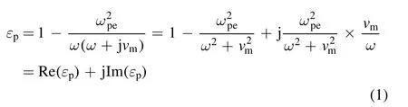
Simulations of PPCs with different configurations were completed by use of COMSOL Multiphysics software based on the finite element method.Here,a brief description of the model is provided.As shown in figure 1(a),the PPCs consist of five circular plasma rods immersed in background air whose dielectric constantεair=1.The radius of the rod R=7.5 mm and the lattice constant of the PPC L=60 mm.The dielectric constant of the plasmaεpcan be derived from the well-known Drude model[38]:νm=NδC(υ)υis the electron collision frequency between

whereωpeis the plasma frequency,neis the electron density,e is the electron charge,meis the electron mass,and ω is the frequency of the incident electromagnetic(EM)wave.electrons and neutrals,whereυis the electron speed,N is the number of neutral atoms per unit volume andδC(υ)is the collision cross-section.In this preliminary work,the influence of the electron collision frequency is not considered(νm=0)and the plasma density in the plasma column is set asne= 4 ´1011cm-3,which is invariant between different models unless specifically mentioned in figure 3.We define these plasma structures as 1D PPCs which refer to 1D periodic PCs.Such plasma structures can be realized by using an array of gas discharge tubes designed in different sizes,shapes and materials.In these gas discharge tubes,the electron density is generally in the order of 1011cm−3,which can be tuned by changing the discharge current or voltage[18–22].The collision frequency is low because of the low gas pressure,and has negligible influence on the positions of the band gaps[17,39].Note that the quartz walls of the discharge tubes are not taken into account in this model for simplicity.Only the effects of the structural configurations and the material properties upon the band properties have been concentrated on.
In the model,a transverse magnetic(TM)plane wave with the wave vectorkxand field components(Ez,Hx,Hy)passes through the PPCs along the x-axis.The upper and lower boundaries(green thick lines as shown in figure 1(a))are set as perfect magnetic conductors so that the incident and transmitted waves can be confined in the simulation area.The mesh division is selected as the free triangle mesh.The largest mesh element is set as 3.7×10⁻⁴m,the smallest mesh element is 2.5×10⁻⁵m,and the curvature factor is 0.3.We define the left port as Port 1 and the right port as Port 2,which are the emitter and receiver of the TM waves,respectively.The positions and sizes of the band gaps can be identified clearly through the transmission spectra of EM wavesS21.
3.Results and discussion
3.1.1D ternary plasma photonic crystals
The first structure under study is a kind of ternary PPC,in which the third material is introduced into the scattering element.As shown in figure 1(a),half of the circular rod is filled with the plasma,while the other half is filled with the dielectric material with the dielectric constantεn.We define this dielectric material as the third material,sinceεnis different from the dielectric constants of the plasmaεpand the air backgroundεair.Such a 1D PPC can be considered as a 1D planar PPC,which consists of alternating layers of the effective scattering medium and the air[25],as shown in figure 1(b).The effective scattering medium,whose crosssection is a square with the side lengthdeff=2R,is a composite material consisting of plasmas(εp),the third material(εn)and the air(εair).The dielectric constant of the effective scattering mediumεeffcan be described as

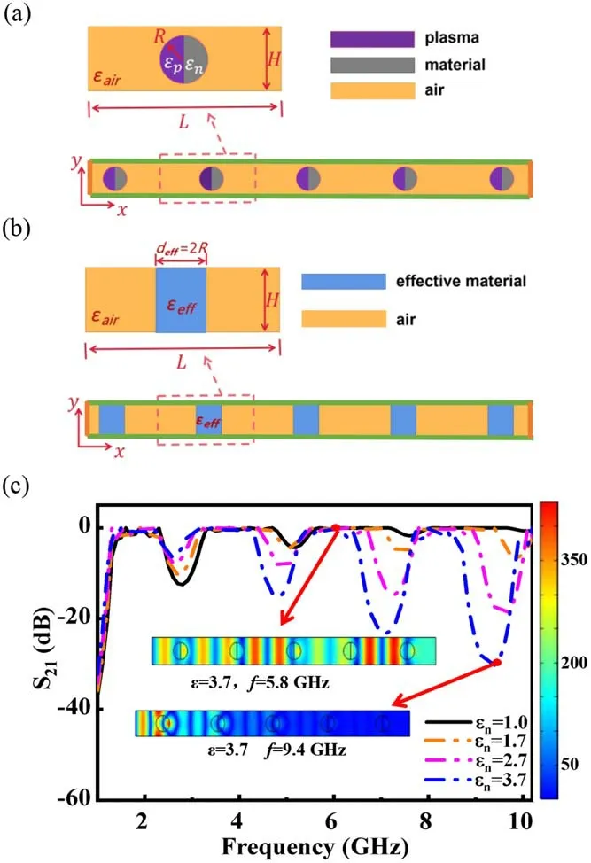
Figure 1.The physical model and the transmittance spectra of 1D PPCs with different dielectric constants of the third materialεn .(a)The schematic diagram of the 1D PPC,where different colors represent different materials;(b)1D planar PPC that consists of alternating layers of effective scattering medium and air;(c)the microwave transmission spectra for the PPCs.The simulation parameters are:R=7.5 mm,H=24 mm,ne=4×1011cm−3,L=60 mm.
f=5.8 GHz,the microwaves can propagate through the PPC structure successfully.In contrast,when the frequency of microwaves falls into the band gaps,for instance f=9.4 GHz,the field Ezis strong at the regions near the first column but attenuates rapidly with EM waves propagating forward.The formation of band gaps results from Bragg scattering due to spatial periodic arrangement of the materials,which is analogous to the electronic band gaps in semiconductors.One can see that an increase ofεnleads to more band gaps as well as larger high-order band gaps.Whenεn>1,four band gaps have been produced and the position of the center frequency for each band gap moves to the lower frequency.Nevertheless,the positions of the cutting-off frequencies are almost invariant,because the cutting frequency is strongly related to the plasma frequencyωpewhich is fixed here.Moreover,the size of the first band gap is reduced obviously asεnincreases,while the widths and depths of the second to the fourth PBGs are increased significantly.
To further characterize the influences ofεnon the properties of the band gaps,a detailed analysis of the changes of the center frequencies and the widths of different orders of the band gaps has been provided in figure 2.It can be seen that(1)the center frequencies for each order of the band gaps decrease asεnincreases(figure 2(a));(2)the widths of the first PBG decrease monotonously with increasingεn,while the widths of the third and fourth PBGs are increased significantly(figure 2(b));and(3)the second PBG can be considered as a critical band gap,whose size decreases first whenεnchanges from 1.0 to 1.7,then increases whenεnis increased furthermore(figure 2(b)).The changes of band gaps are mainly attributed to the fact that an increase ofεnresults in an increase ofεeff,as given in equation(3).As a result,the permittivity ratio between the scattering elements and the air backgroundhas been increased so that the incident EM waves will be scattered more strongly and the PGBs are more likely to appear[5].Here the introduction of a third material into the plasma lattice brings about new features for the band diagrams.An increase ofεnenlarges the high-order band gaps,while reducing the sizes of low-order band gaps.The sensitivity of the band gaps to the properties of the third materials provides guidance for the selection of optimal materials for fabricating high-performance PPCs.
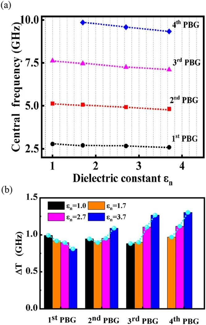
Figure 2.Dependence of the center frequencies(a)and band gap widths(b)on the dielectric constants of the third materialεn .The blue dashed lines in(b)indicate the changes of the widths of different orders of the band gaps when increasingεn from 1 to 3.7.
We next propose a new design of ternary PPCs in which gaseous plasmas with electron densityne2are used as the third material.As shown in figure 3(a),the left part of the plasma column is filled with the plasma withne1=4×1011cm−3and the right part is filled with the plasma whose electron densityne2can be changed from 9×1010cm−3to 2×1012cm−3.Such PPCs can be realized by using an array of pairs of semicircular gas-discharge tubes,which are driven by different applied voltages.It is shown that the changes ofne2have a great impact on the microwave transmittance properties of PPCs,as illustrated in figure 3(b).First,more band gaps have been produced,and the positions of band gaps move to the higher frequency with an increase ofne2.One can see that three band gaps are produced whenne2≤ne1,while four band gaps form whenne2is larger thanne1.The transmittance characteristics of PPCs can be clearly identified through the distribution of Ez,as shown in the insets of figure 3(b).If the frequency falls into the band gap,f=3.3 GHz for example,the electric field attenuates rapidly near the region of the first column and disappears with the EM waves propagating forward.By contrast,if the frequency of microwaves locates in the pass band,f=9.1 GHz for instance,the microwaves can propagate through the PPC structure successfully.Second,the cutting-off frequencies shift to the higher frequency asne2increases.It increases from 1.48 GHz to 2.31 GHz whenne2changes from 9×1010cm−3to 2×1012cm−3.This is attributed to the fact that the cutting-off frequency strongly depends on the plasma frequencyωpe,which is increased with the electron density.Third,an increase ofne2leads to dramatic enlargement of the band gaps.This is highly necessary in real applications of PPCs,and enables tunable control of microwave radiation for a wide range of applications.
Figure 3.The physical model(a)and the transmittance spectra(b)of 1D PPCs with different electron densities n e2.The simulation parameters are:R=7.5 mm,H=24 mm,ne1=4×1011cm−3,L=60 mm.
Figure 4 presents a detailed analysis of the changes of the center frequencies and the widths of different orders of the band gaps as a function ofne2.It is evident that the center frequency for each order of band gaps upshifts to a higher frequency asne2increases(figure 4(a)).Moreover,the widths of four band gaps increase monotonously with increasing ofne2(figure 4(b)).The lower the order of the band gap,the larger the increase of the band gap width.These results can be explained by use of the effective medium theory as demonstrated previously[25].Similar to figure 1(b),this 1D PPC can be considered as a 1D planar PPC,which consists of alternating layers of the effective scattering media and the air.Here the effective scattering medium is a composite material consisting of plasmas with different electron densities(εp1andεp2)and the air(εair).Due to Bragg reflection,the central frequency of the band gaps for such 1D PPCs can be given by[40],
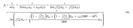
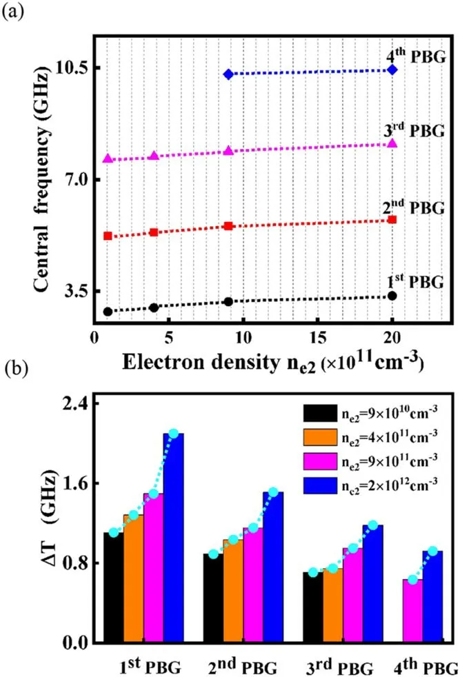
Figure 4.Dependence of band gap positions(a)and band gap widths(b)on the electron density n e2.The blue dashed lines in(b)indicate the changes of the widths of different orders of the band gaps,when increasingne2 from 9×1010cm−3 to 2×1012cm−3.
wheref0,λ0,m are the central frequency,central wavelength and an integer,respectively.are the areas of the plasmas with the electron densityne1andne2,respectively.deff=2R,dair=L–2R are the widths of the effective scattering material layer and the air layer.Consequently,an increase ofne2leads to a decrease ofεeffand thus an increase off0.Meanwhile,the permittivity ratio between the air and the effective scattering materialis increased,giving rise to wide band gaps[5].
3.2.1D superlattice plasma photonic crystals
We preface the discussion of the following simulation works with a few comments about the definition of superlattices.Briefly,plasma lattices can be divided into two categories according to their configurations:one is the simple lattice,and the other is the superlattice.A simple lattice is constituted by the uniform plasma columns with completely identified parameters.A superlattice is a composite structure that consists of two or more simple sublattices.The structural parameters between different sublattices can be different,such as the different size,shape and dielectric constant(plasma density)of the scattering elements.Recently,a new type of superlattice PCs is suggested,which introduces a smaller diameter rod into the center of each unit cell[11].The band gap widths of superlattices PCs can be significantly enhanced since the degeneracy in the bands is lifted by the symmetry breaking.Notwithstanding the superior features for such superlattice structures,few works on this issue have been carried out so far.In this part,we rationally modify the superlattice plasma structures and search for optimal configurations to achieve the improved band gaps.
Figure 5 presents a class of superlattice PPCs with the addition of different numbers of small-sized plasma rods in the primitive unit cell.The number of small-sized plasma columns in each unit cell N2is changed from 0 to 4.One can see that three noticeable band gaps have been produced with different N2(figure 5(b)).The microwaves whose frequency locates in the range of the band gaps cannot pass through the plasma crystal,as manifested by the distribution of Ezin the inset.With an increasing of N2,the positions of band gaps and the cutting-off frequencies both upshift to higher frequencies.Figure 6 presents a detailed analysis of the center frequencies and band gap widths with an increasing of N2.One can see that the center frequencies of the band gaps increase with N2,which shifts from 3.05 GHz to 3.74 GHz with Δf=0.69 GHz for the first band gap,5.41 GHz to 5.83 GHz with Δf=0.42 GHz for the second band gap,and 7.78 GHz to 8.04 GHz with Δf=0.26 GHz for the third band gap,respectively(figure 6(a)).The frequency shifting of the first PBG is the most remarkable.As shown in figure 6(b),the changes of the widths of band gaps are more complicated and an optimal value of N2can be obtained.For the first PBGs,the width of the band gaps reaches the maximum when N2=1 and then it starts to decrease as N2increases.However,for both of the second and third PBGs,the widths of the band gaps reduce monotonously with increasing of N2.Thus our result provides an optimal number of the small-sized plasma columns to create large band gaps for plasma superlattices(N2=1).We suggest that this design scheme can be potentially extended to 2D or 3D crystals to achieve increased band gaps.
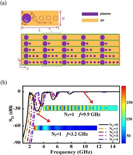
Figure 5.The physical model(a)and the transmittance spectra(b)of 1D superlattice plasma structures with different numbers of smallsized plasma columns in each unit cell.The simulation parameters are:R1=7.5 mm,R2=3.5 mm,H=20 mm,ne=4×1011cm−3,L=60 mm.The number of the small-sized plasma columns in each unit cell N2 is increased from 0 to 4.
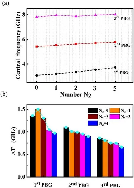
Figure 6.Dependence of the center frequencies(a)and band gap widths(b)on the number of the small-sized plasma columns in each unit cell N2.The blue lines in(b)indicate the changes of the widths of different orders of the band gaps when increasing N2 from 0 to 4.
Finally,we would like to suggest a novel annular superlattice plasma structure as displayed in figure 7.The lattice is composed of large and small plasma columns,in which the small-sized plasma columns possess a circular air hole in the center.Based on the results described in figures 5 and 6,the number of small-sized plasma columns in the primitive unit cell is selected as N2=1.Here,the influences of the radius of the air hole r on the microwave transmission characteristics of superlattice PPCs have been investigated.It is shown that an increase of r gives rise to a deeper and wider first band gap,while it has a negligible effect on high-order band gaps.One can see from figure 7(b)that when r=0,two noticeable forbidden band gaps have been produced,which locate at 3.37 GHz and 5.56 GHz,respectively.Moreover,the second band gap is obviously deeper and wider than the first one.With an increase of r,the first PBG becomes remarkably wider and deeper;meanwhile,the position of the band gap moves to the lower frequency.By contrast,the positions of the second band gaps are nearly invariant and the sizes of the band gaps change little when r has been varied.
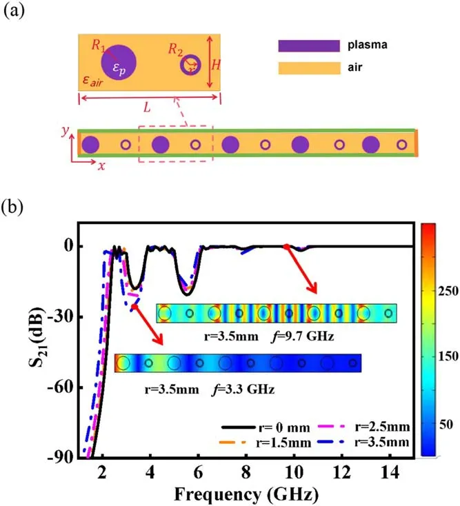
Figure 7.The physical model(a)and the transmittance spectra(b)of 1D annular superlattice PPCs with different radii of the air hole r.The simulation parameters are:R1=7.5 mm,R2=3.5 mm,H=20 mm,ne=4×1011cm−3,L=60 mm.
The changes of the center frequencies and the band gap widths with an increasing of r have been studied in figure 8.One can see that the center frequencies downshift from 3.37 GHz to 3.20 GHz with Δf=0.17 GHz for the first band gap,5.56 GHz to 5.46 GHz with Δf=0.1 GHz for the second band gap,and 7.86 GHz to 7.81 GHz with Δf=0.05 GHz for the third band gap.The higher the order of the band gap,the smaller the downshifting of the center frequencies will be.Moreover,as shown in figure 8(b),the width of the first band gap increases monotonously from 0.9 GHz to 1.18 GHz when r changes from 0 to 3.5 mm.However,small changes take place for the widths of the second and third band gaps.Consequently,the variation of r has a great impact on the widths and positions of the first band gap,while it has negligible influence on the high-order band gaps.Larger band gaps can be achieved by utilizing thinner annular plasma columns.

Figure 8.Dependence of the center frequencies(a)and band gap widths(b)on the radii of the air hole r.The blue lines in(b)indicate the changes of the widths of different orders of the band gaps when increasing r from 0 to 3.5 mm.
The changes of the band diagrams herein are attributed to a combined effect of the filling fraction of the plasma and the structural configuration of the PPC.One can see that the filling fraction of the plasma increases with an increase of N2in superlattice PPCs(figure 5(a))or with a reduction of r in annular superlattice PPCs(figure 7(a)).However,changes of the band diagrams for these two structures are much different,as shown in figures 5(a)and(b),which indicates that the structural configuration plays a significant role in the formation of the band gaps.In PCs,the absolute band gaps that are polarization-insensitive can be remarkably increased in annular structures[12].The annular structure is also an effective route to integrate the unusual dispersion effects of PCs,including the negative refraction,self-collimation and zero refraction effects to realize multifunctional beam steering devices[13].By increasing the inner radius of annular air rings,the band properties can be sufficiently improved[41].This provides additional tunability on the crystal structures,which presents more possibilities in dispersion engineering.On the other hand,the superlattice structure is a promising candidate for the fabrication of high-performance PCs.By decreasing the symmetry through the introduction of different sizes of scatters into the lattice,large band gaps can be produced,since the degeneracy of photonic bands at high symmetry points in the Brillouin zone can be lifted[11].In this work,the proposed concept of annular superlattice PPCs integrates the designs of superlattice PCs,annular PCs and plasmas,which will bring about more promising features and provide stirring potential in applications such as imaging,sensing,beam steering and photonic integrated circuits.In addition,it offers enlightenment for the design of new functional meta-materials in other fields.
4.Conclusions
In summary,we propose differ ent types of 1D PPCs,which have uniquely designed superlattice structures or incorporate the third material into the primitive unit cell.The influences of the properties of the third material,as well as the structural configurations of suplerlattices on the band diagrams of PPCs,have been studied.It is found that,for the ternary PPCs with incorporation of a third dielectric material,an increase ofεnenlarges the high-order band gaps while reducing the loworder band gaps.Moreover,the center frequency of each band gap downshifts to the lower frequency.For the ternary PPCs with incorporation of gaseous plasmas as the third material,an increase ofne2gives rise to more band gaps and a dramatic increase in the widths of the band gaps.Furthermore,a class of superlattice PPCs fabricated by introducing small-sized plasma columns into the primitive unit cell has been suggested.The optimal number of the small-sized plasma columnsN2=1is provided.A novel annular superlattice PPC is proposed,and larger band gaps can be achieved by use of thinner annular columns.Our results provide guidance for choosing optimal materials and structural configurations to fabricate high-performance PPCs.Such PPC-based metamaterials can potentially be extended to 2D or even 3D crystals,and find promising applications in the manipulation of microwaves or terahertz waves.A further study of the underlying mechanism of the interaction between microwaves and plasmas in these novel PPCs will be carried out in future.
Acknowledgments
This work was supported by National Natural Science Foundation of China(No.11875014),and the Natural Science Foundation of Hebei Province(A2017201099).W L Fan wishes to thank Dr Li Guan for helpful discussions.
猜你喜欢
汽车实用技术(2022年12期)2022-07-05
老年博览·上半月(2022年6期)2022-06-30
高教学刊(2022年13期)2022-05-24
教学与管理(小学版)(2022年5期)2022-05-17
大观·东京文学(2020年3期)2020-05-25
新天地(2020年4期)2020-05-13
新天地(2020年4期)2020-05-13
文化交流(2020年3期)2020-03-18
美与时代·城市版(2019年6期)2019-09-17
蓝盾(2017年11期)2017-12-25
 Plasma Science and Technology2021年6期
- Plasma Science and Technology的其它文章
- Diagnostics of a microhollow cathode discharge at atmospheric pressure
- The investigation of OH radicals produced in a DC glow discharge by laser-induced fluorescence spectrometry
- Multiple current peaks and spatial characteristics of atmospheric helium dielectric barrier discharges with repetitive unipolar narrow pulse excitation
- Study of the influence of discharge loop parameters on anode side on generation characteristics of metal plasma jet in a pulsed vacuum discharge
- Nonlinearity of initiating and extinguishing boundaries of DBDs with airflows
- Study of double-chamber air arc plasma torch and the application in solid-waste disposal