
A Peridynamic Approach for the Evaluation of Metal Ablation under High Temperature
2023-01-21 08:05HuiLiLipingZhangYixiongZhangXiaolongFuXuejiaoShaoandJuanDu
Hui Li,Liping Zhang,Yixiong Zhang,Xiaolong Fu,Xuejiao Shao and Juan Du
Science and Technology on Reactor System Design Technology Laboratory,Nuclear Power Institute of China,Chengdu,610200,China
ABSTRACT In this paper,the evaluations of metal ablation processes under high temperature,i.e.,the Al plate ablated by a laser and a heat carrier and the reactor pressure vessel ablated by a core melt,are studied by a novel peridynamic method.Above all,the peridynamic formulation for the heat conduction problem is obtained by Taylor’s expansion technique.Then,a simple and efficient moving boundary model in the peridynamic framework is proposed to handle the variable geometries,in which the ablated states of material points are described by an additional scalar field.Next,due to the automatic non-interpenetration properties of peridynamic method,a contact algorithm is established to determine the contact relationship between the ablated system and the additional heat carrier.In addition,the corresponding computational procedure is listed in detail.Finally,several numerical examples are carried out and the results verify the validity and accuracy of the present method.
KEYWORDS Peridynamics;metal ablation;moving boundary model;contact algorithm;reactor pressure vessel
1 Introduction
The metal ablation under high temperature is ubiquitous in many engineering problems,such as the welding of the steels,the laser strengthening of the aluminum alloys,and the ablation of the reactor pressure vessels (RPVs) caused by a core melt in serious accidents,etc.Importantly,the properties of these metal materials and structures may change dramatically after the thermal ablation,which could eventually improve or reduce the levels of strength,stability,workability,safety of the materials and structures,and so on.Therefore,it is very essential to study metal ablation problems.During the past several decades,studies of metal ablation problems have been conducted by many researchers from the aspects of theories,experiments and simulations.For instance,the characteristics of the thermal ablation,such as the microtopologies,the thermal boundaries and the thermal damages,were investigated by the experimental and numerical methods[1–4].The welding methods were studied for different metal materials,such as laser welding and friction stir welding methods[5–7].Further,the surface and toughness hardenings of metal materials through laser ablation were researched by the theoretical,experimental and numerical methods[8–11].In addition,Anderson et al.[12]investigated the heat transfer experimentally within the AP600 containment under postulated accident conditions.Theofanous et al.[13]and Guan et al.[14]studied the heat distributions and convective boundaries of the RPV based on a two-layer structure of core melt.Zhan et al.[15]analyzed the ablation and thermal stresses of the RPV under heating by core melt on the basis of a moving boundary scheme in the finite element framework.Although these works mentioned above have provided reliable approaches or routes for the evaluations of the metal ablation problems,novel and efficient computational methods are still of great importance for the more complex metal ablation problems,such as the coupling heat conduction,ablation and contact problems.
In the last twenty years,nonlocal peridynamics proposed by Silling [16] has attracted a lot of researchers’interests due to its natural advantages in dealing with discontinuous and contact problems.The peridynamic method is expressed by an integral motion equation and mainly contains two kinds of forms,i.e.,the bond-based peridynamics and the state-based peridynamics.Since the proposal of the peridynamic method,its basic theories have been deeply developed from several perspectives[17–26].Meanwhile,the peridynamic method has been widely extended to many fields.For example,an improved peridynamic fracture model for the analyses of brittle fracture problems was developed by Huang et al.[27]and Hu et al.[28].A peridynamic contact algorithm was proposed by Ye et al.[29]for the propeller-ice contact problems and Xue et al.[30]for the thermal contact problems.A peridynamic formulation for transient heat conduction was presented by Oerkus et al.[31–33] to simulate the heat conduction problems in bodies with evolving discontinuities.Wang et al.[34] developed a dual horizon peridynamic method for the thermal diffusion analysis.Further,Ouchi et al.[35–37]proposed a coupling peridynamic approach for the consolidation and dynamic analyses of saturated porous media.Silling et al.[38]and Li et al.[39]developed a peridynamic model for the nonlinear analyses of bimodular truss structures,tensegrity structures and membranes.In addition,the peridynamic theory was also used to simulate the chemical corrosion,damage and fracture problems[40–44].As demonstrated by these successful applications of the peridynamic method to commendably deal with the heat conduction problems,contact problems and discontinuous problems,the method shows great promise for the simulation of the thermal ablation problems in metals.
This paper aims to develop a nonlocal peridynamic method for the evaluation of the metal ablation under high temperature.In the method,the peridynamic formulation for the heat conduction problem is obtained by Taylor’s expansion technique.To describe the moving boundary of the system caused by the thermal ablation,a simple and efficient moving boundary model in the peridynamic framework is proposed,in which the ablated states of the material points are represented by an additional scalar field.It is worth mentioning that due to the introduction of the scalar field,there is no need to update the computational domain and the horizon of material points during the whole computational process,which can reduce computational costs.Furthermore,a peridynamic contact algorithm is presented to determine the contact relationship between the ablated system and the heat carrier,which can be simply and conveniently achieved because of the automatic non-interpenetration properties of the peridynamic method.It is noted that during the calculation,all the material points,that is,the boundary material points (BMP),internal material points (IMP) and ablated material points (AMP),will change types due to the occurrence of the thermal ablation.In addition,the computational procedure of the present method is given out in detail and the effectiveness of the method is demonstrated by several representative numerical examples.
The remaining sections of this paper are organized as follows.Section 2 shows the peridynamic formulation for the transient heat conduction problem and the derivation of the micro-conductivity on the basis of the Taylor’s expansion technique.The moving boundary model in the peridynamics is established in Section 3 and the peridynamic contact algorithm is presented in Section 4.In Section 5,the computational implementation of the present method is described in detail.Moreover,several representative numerical examples are illustrated in Section 6 and the results verify the validity and accuracy of the present method.Finally,some concluding remarks are presented in Section 7.
2 Peridynamic Formulation for the Transient Heat Conduction Problem
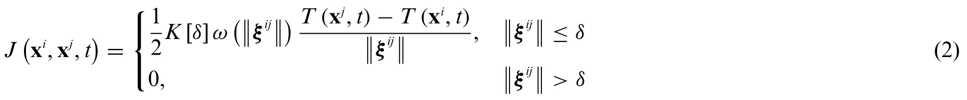
On the basis of the non-local peridynamic model and the corresponding spatial uniform discretization as shown in Fig.1,the peridynamic formulation for the transient heat conduction problem can be expressed as[33]:

whereρandcare the mass density and the specific thermal capacity of the material,respectively.ξij=xj-xi,in which xiand xjindicate the coordinates of thei-th andj-th material points.Vxiis the volume andHxiis the neighborhood of the material point xiwith a certain horizonδ.T(xi,t)presents the temperature of the material point xiat timet.J(xi,xj,t)is the heat flow density that the material point xjoperates on the material point xiand it can be expressed as
whereK[δ] is the micro-conductivity for the isotropic and homogeneous materials,and it can be obtained according to the local thermal conductivitykin the classical heat transfer model.It is noted that the micro-conductivityK[δ]is a variable value determined by the non-local effects of the material.is the weight function that indicates the range and degree of the long-range effects of the heat diffusion between the material points xiand xj.Moreover,on the basis of the expression ofJ(xj,xi,t),it yields thatJ(xi,xj,t)=-J(xj,xi,t).Next,in order to obtain the micro-conductivityK[δ],substituting the expressions ofJ(xi,xj,t)andJ(xj,xi,t)into Eq.(1)yields that

Figure 1:Schematic diagram of(a)a non-local peridynamic model and(b)a spatial discretization for evaluation
In addition,based on Taylor’s expansion technique,the temperatureT(xi,t)can be approximately expressed as a function expanded at the material point xj,that is

Substituting Eq.(4)into Eq.(3)yields
Due to the symmetric property of the integral domain,e.g.,Hxiis circular for two-dimensional problems and spherical for three-dimensional problems,the odd-ordered terms in Eq.(5) can be omitted.Then we can obtain that
in which the second order tensorindicates the nonlocal thermal conductivity in the peridynamics and it is given by

whereandare the components of the vectorξij.It can be seen from Eq.(7)thatis a diagonal matrix and it can be expressed as=diagfor the two-dimensional problems.Then,Eq.(6)can be rewritten as
It is noted that Eq.(8) is similar to the governing equation of the classical heat transfer model.Therefore,it is expected from Eq.(8) that the nonlocal thermal conductivities ˜K11and ˜K22in the peridynamic model converge towards the local thermal conductivitykin the classical heat transfer model.Therefore,we can obtain that

Next,two kinds of weight functions are considered,i.e.,=1 for the constant weight function andfor the triangular weight function.For one-dimensional problems,
Consequently,the peridynamic formulation of the one and two-dimensional transient heat conduction problems with the triangular weight function,for example,can be expressed as

and

In addition,both the Dirichlet (temperature) and Neumann (heat-flux) boundary conditions are considered in this paper.To impose these above boundary conditions,the fictitious material points are added outside the corresponding boundaries.For the Dirichlet boundary condition,the given temperature values are directly applied to the additional fictitious material points and remain constant all the time.For the Neumann boundary conditions,the given heat-flux values are indirectly imposed on the additional fictitious material points through the linear distributed temperatures as shown in Fig.2.That is,after obtaining the temperatures of actual material points at every time step,the temperatures of fictitious material points are updated from the corresponding temperatures of boundary material points adding a temperature gradient related to the boundary heat-flux.In other words,for the Neumann boundary condition,the values of the temperatures of fictitious material points can be obtained by a temperature extrapolated method at every time step.The material point xiis imposed a given heat fluxq,for example,the expression of the linear distributed temperatures on the fictitious material points outside the material point xias shown in Fig.2 can be written as

whereT(xi,j,t)represents the temperature on thej-th fictitious material point outside the material point xi,Δxis the size of the uniform material points andm=is related to the number of material points inside the neighborhoods.
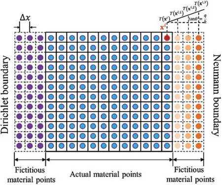
Figure 2:Schematic diagram of the fictitious material points and imposing the Dirichlet and Neumann boundary conditions
3 Moving Boundary Model
The thermal ablation is a common and direct way that may arise the serious failure for the metal structure under high temperature.The material is ablated while the temperature of the material reaches to its critical melting temperature of the material.Obviously,the geometry of the metal structure is changing along with the thermal ablation process.Therefore,to evaluate the thermal ablation process of the metal structure heated by a heat carrier with very high temperature,it is necessary to consider the moving boundaries besides the heat diffusion in the structure.For the finite element method,it is complex and uneconomical to deal with the problems with moving boundaries because the corresponding heat transfer matrix of the system needs to be reassembled when its geometry is changed during the numerical simulation.Fortunately,the peridynamics is a nonlocal method that expressed by an integral equation and the structure is discretized into many material points while a meshless method is adopted [17],which makes it convenient and prone to handle the moving boundaries.In the peridynamic moving boundary model,the whole material points are divided into three categories during the thermal ablation process of the metal structure as shown in Fig.3.They are the internal material point (IMP),the boundary material point (BMP) and the ablated material point (AMP),respectively.During the calculation,we need to estimate whether the temperatureT(xi,t)of the material point xireaches the critical melting temperatureof the material.Meanwhile,during the calculation,the three kinds of material points will change types due to the occurrence of the thermal ablation.In addition,a scalarφ(xi,t)is introduced to describe the ablated state of the material point xi,that is

in which,max{T(xi,t)}presents the maximum temperature of the material point xiduring the time history.It is noted that Eq.(15)can embody the irreversible features of the thermal ablation process.In addition,it can be seen from Eq.(15)thatφ(xi,t)=1 presents the un-ablated state of the material point xiwhileφ(xi,t)=0 denotes the ablated state of the material point xi.

Figure 3:Moving boundary model:(a)initial boundary,(b)interim boundary and(c)final boundary,in which IMP is the internal material point,BMP is the boundary material point and AMP is the ablated material point
Taking the moving boundaries into account and substituting Eq.(15) into Eq.(3),the peridynamic formulation for the thermal ablation problem under high temperature can be expressed as

in which,

It is emphasized that the seeking of the neighborhood for each material point only needs to be operated once at the initial time step due to the introducing of the scalarφ(xi,t)for the moving boundary problems,which is a novel and economical technique to evaluate the thermal ablation process in metal under high temperature.
4 Contact Algorithm
In this paper,the thermal ablation process of the metal structure caused by a heat carrier with high temperature is evaluated.Except for the heat diffusion problem,the contact problem should also be considered in this simulation.Fortunately,the automatic non-interpenetration properties of the peridynamic method can naturally deal with the contact problem [45].On the basis of the moving boundary model mentioned in Section 3,the contact algorithm for the peridynamic method is presented in this section.Fig.4 depicts the non-contact and the contact states between the ablated metal structure and the heat carrier.For this thermal ablation problem,we consider that the contact state of the metal structure and the heat carrier should be maintained all the time.Therefore,the minimum distancedbetween these two bodies along the moving direction n should be calculated at every time step.In addition,the distancedi,j H,Mbetween the boundary material points of these two bodies along the moving direction n can be expressed as

where yiand yjpresent the current coordinates of the material points xiand xj,respectively.BMPMand BMPHdenotes the collections of the boundary material points of the metal structure and the heat carrier,respectively.

Consequently,the displacement increment Δuof the heat carrier at the current time step can be expressed as in which,is the distance between the material points xiand xjwhen the representative spaces of these two material points are contact critically.In addition,it is noted that the stresses and deformations of the metal structure and the heat carrier are not considered in the present thermal ablation problem.In other words,their contact states are maintained and their contact forces are zero all the time.In our future work,the mechanical deformations of the metal structure and the heat carrier will be taken into account for the analyses of the thermal ablation problem.
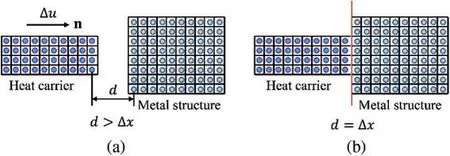
Figure 4:Illustrations of contact model:(a)non-contact state and(b)contact state
5 Computational Implementations
On the basis of the discretization in spatial and temporal,the discretized peridynamic formulation for the thermal ablation problem in metal under high temperature can be expressed as

wherenis then-th time step andNxiis the number of the material points in the horizon of material point xi.
In addition,the computational procedure of the proposed peridynamic method for the thermal ablation problem of the metal structures is listed in the following:
(1) Set the control parameters (size of material points Δx,horizon of material pointsδ,time step Δt,total timetf,etc.),the material parameters(mass densityρ,thermal conductivityk,thermal capacityc,critical melting temperature,etc.) and the geometrical and boundary information.
(2) Set the initial variables,such as the initial temperatureT0(xi,t),the initial state scalarφ0(xi,t)=1,the initial coordinates x,etc.
(3) Loop for the time step(initializen=0).
(3.1)Setn=n+1.
(3.2)Calculate the displacement increment Δuon the basis of Eq.(19),if Δu>0,update the coordinates of the heat carrier and the new neighborhood of the material points;otherwise,go to Step(3.3).
(3.3)Calculate the current temperature field on the basis of Eq.(20).
(3.4)Update the ablated state scalarφ(xi,t)for each material point xi.if max{T(xi,t)}≥,φn(xi,t)=0;otherwise,φn(xi,t)=1.
(3.5)Update the classification of the material points,i.e.,IMP,BMP and AMP.
(4) Ift≥tf,go to Step(5);else,go to Step(3.1).
(5) Finish the computations and output the results.
In addition,the thermal conductivity between the metal structure and the heat carrier can be given by

in which,dHanddMare the distances from the material points xiand xjto the contact surface,respectively.Moreover,Fig.5 shows the definitions of the distances,the contact surface and the interaction between the material points of the metal structure and heat carrier.
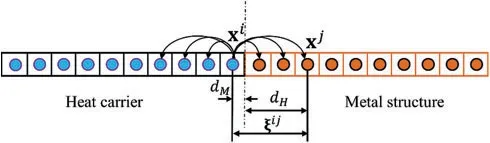
Figure 5:Illustrations of the interaction between the material points of the metal structure and heat carrier
6 Numerical Examples
In this section,several representative numerical examples are considered to evaluate the validity and accuracy of the proposed method.In addition,the relative errors of the temperature fields are defined as

whereTPDis the results obtained by the present method,TRstands for the reference solutions andNis the total number of the material points of the metal structure.
6.1 Heat Conduction in a Plate
Firstly,a simple transient heat conduction in a 2D plate is considered to investigate the validity and accuracy of the present method.As shown in Fig.6,the length and width of the plate areL=H=1.0 m.For simplicity,the material properties are chosen to be unit values,i.e.,k=1.0 W/(m·°C)andρc=1.0 J/(m3·°C).
The initial and boundary conditions are as follows:
whereT0=0°C andT1=100°C.In addition,the corresponding analytical solutions for this problem can be expressed as[46]
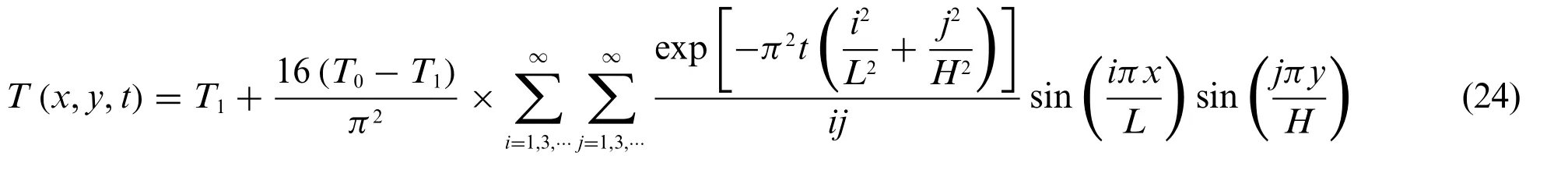
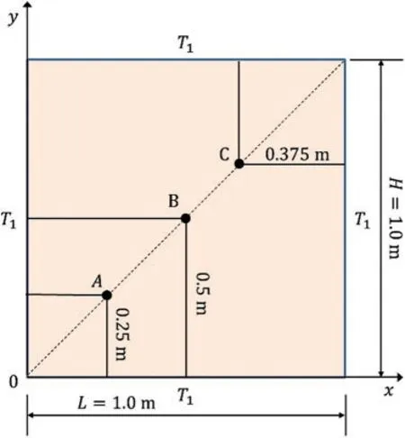
Figure 6:Sketch and boundary conditions of the 2D transient heat conduction problem
For the numerical simulation,three kinds of horizons of material points are taken into account,i.e.,δ=Then,four kinds of discretization in spatial are considered,i.e.,L=H=100Δx,160Δx,200Δxand 250Δx,in which the corresponding numbers of the material points along the radius of the neighborhood arem=≈2.71,4.33,5.42 and 6.77 withδ=,respectively.The time step is chosen as 1.0×10⁻⁶s.
Fig.7 depicts the relative errors changing with the horizons and sizes of the material points.It can be seen from these curves that the horizonδof the material points is smaller,and the relative errors are smaller whenmis fixed,which reveals that it is consistent with theδ-convergence.Moreover,the relative errors are also consistent with them-convergence,i.e.,the relative errors should be smaller when the value ofmis smaller.It is also noted that the minimum relative error is 0.24%withδ=andm=4.33 among these results obtained by different computational parameters,which is a result of the numerical error and the difference between the nonlocal theory and the local theory.Based on the convergence behavior of the results for the present method,L=H=160 Δxandδ=are selected in the following discussions.Fig.8 shows the temperature history curves of points A,B and C obtained by the present method and from the analytical solution.The temperature distributions along the line ofy=0.5 m at timet=0.03 s,0.06 s and 0.09 s are plotted in Fig.9,which demonstrates that the results obtained by the present method fit well with the analytical solutions.In addition,Fig.10 shows the temperature contours at timet=0.03 s,which further verifies the validity and accuracy of the present method for the heat conduction problems.
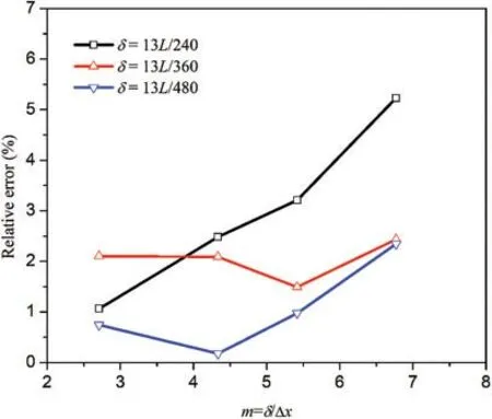
Figure 7:The relative errors changing with the horizon and size of the material point
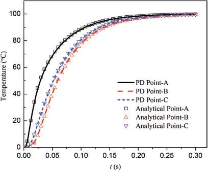
Figure 8:Temperature history curves at different points
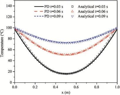
Figure 9:Temperature distributions along the line of y=0.5 m at time t=0.03 s,0.06 s and 0.09 s,respectively
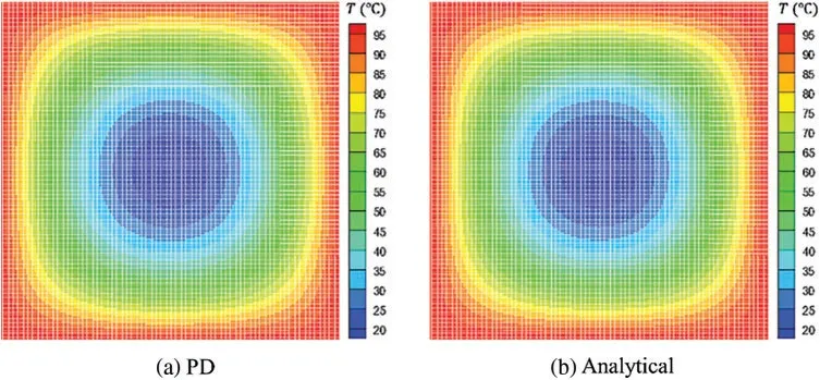
Figure 10:Temperature contours obtained by different methods at time t=0.03 s
6.2 An Al Plate Heated by a Laser
To investigate the validity and effectiveness of the present method for the evaluation of metal ablation under high temperature,an Al plate heated with a laser is considered.As shown in Fig.11,the dimension of the Al plate is 0.1×0.1 m2.The heat source of the laser is simplified and the corresponding laser intensity follows the exponential distribution [4],i.e.,S=αI(x,y)S0,whereS0=2.376×10⁷KW/m2,α is a coefficient with initial value of 1.0.For the material properties of the aluminum,k=237.0 W/(m·°C),c=880 J/(kg·°C)andρ=2700.0 kg/m3.The critical melting temperatureof the Al plate is 660°C.For the initial and boundary conditions,the initial temperature isT0=0 for the whole Al plate and all of the edges are insulated.Then,the Al plate is discretized into 160×160 uniform material points and the horizon of the material point isThe step for the time integration is 1.0×10⁻⁴s and the total time is 40.0 s.Fig.12 shows the temperature history curves of points A,B and C obtained by the present method.Fig.13 presents the temperature distributions along the line ofx=0.5 m at timet=4.0 s,16.0 s,24.0 s and 40.0 s,in which the horizontal segments stand for the ablated maximum depths in the Al plate.In addition,three kinds of laser intensities are considered to investigate the effect of laser intensity on the speed of ablation.Fig.14 plots the history curves of ablated depth when α=0.8,1.0 and 1.2,respectively.It can be seen from these curves that the laser intensities are much stronger,the speeds of ablation are faster.While the speed of ablation decreases with the increase of time since the laser intensity decreases exponentially.It also reveals that the history curves of the ablated depths are smooth when the laser intensity is very strong,nevertheless,those of the ablated depths are ladder-shaped when the laser intensity is weak.Moreover,Fig.15 shows the temperature contours and ablated shapes withα=1.0 at timet=2.0 s,4.0 s,8.0 s,12.0 s,20.0 s and 40.0 s,respectively,which is consistent with those in reference [4] and presents qualitatively the ablated shapes of the Al plate heated with a laser.
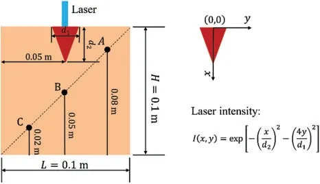
Figure 11:Sketch of the square plate heated with a laser source
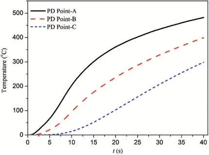
Figure 12:Temperature history curves at different points obtained by the present method

Figure 13:Temperature distributions along the line of x=0.5 m when α=1.0 at time t=4.0 s,16.0 s,24.0 s and 40.0 s,respectively
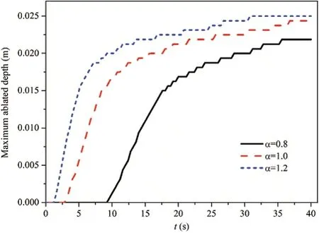
Figure 14:History curves of ablated depth for different laser intensities obtained by the present method

Figure 15:Temperature contours and ablated shapes when α=1.0 at time t=2.0 s,4.0 s,8.0 s,12.0 s,20.0 s and 40.0 s,respectively
6.3 A Rectangle Al Plate Ablated by a Heat Carrier
Next,a rectangle Al plate ablated by a heat carrier is considered to examine the present contact algorithm.As shown in Fig.16,the length and width of the Al plate are 0.1 m and 0.05 m.Besides,those of the heat carrier are 0.02 m and 0.01 m,respectively.The material parameters of the Al plate are:kAl=237.0 W/(m·°C),cAl=880 J/(kg·°C)andρAl=2700.0 kg/m3.The material parameters of the heat carrier are:kc=300.0 W/(m·°C),cc=1300 J/(kg·°C)andρc=8000.0 kg/m3.Further,the critical melting temperature of the Al plate is=660°C.For the initial and boundary conditions,the initial temperature isTAl0=0 for the whole Al plate.The temperature of the lower edge is fixed asTAl1=0 and the heat flux of the other edges is kept open to flow.Three kinds of temperatures of the heat carrier are taken into account,i.e.,Tc0=1400°C,Tc0=1600°C andTc0=1800°C.During the simulation,the variation of the temperature of the heat carrier is changed hypothetically to be uniform.In addition,the energy exchange between the Al plate and the heat carrier is achieved by heat conduction and the effects of the thermal radiation of the heat carrier on the Al plate are neglected.To perform numerical simulating,the Al plate is discretized into 160×80 uniform material points and the horizon of the material point isThe step for the time integration is chosen as 1.0×10⁻⁴s and the total time is 1.0 s.Fig.17 depicts the temperature history curves at point A whenTc0=1400°C,Tc0=1600°C andTc0=1800°C,respectively.Fig.18 plots the temperature distributions along the line ofy=0.5 m whenTc0=1800°C at timet=0.1 s,0.5 s and 1.0 s,respectively.The history curves of ablated depth forTc0=1400°C,Tc0=1600°C andTc0=1800°C are presented in Fig.19,from which it can be seen that the speed of ablation is faster and the value of the final maximum ablated depth(Mad)is much larger when the initial temperatureTc0of the heat carrier is higher.Fig.20 demonstrates the corresponding configurations when the ablated depth achieves the maximum values forTc0=1400°C,Tc0=1600°C andTc0=1800°C,respectively.The maximum ablated depths for these three cases areMad=0.0081 m whent=0.5 s,0.0125 m whent=0.5 s and 0.0175 m whent=0.6 s,respectively.In addition,Fig.21 shows the temperature contours and ablated shapes whenTc0=1800°C at timet=0.02 s,0.1 s,0.2 s and 0.4 s,respectively.
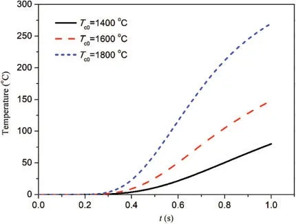
Figure 17:Temperature history curves at point A when Tc0=1400°C,1600°C and 1800°C,respectively

Figure 18:Temperature distributions along the line of y=0.025 m when Tc0=1800°C
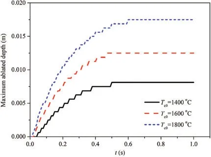
Figure 19:History curves of ablated depth for Tc0=1400°C,1600°C and 1800°C,respectively
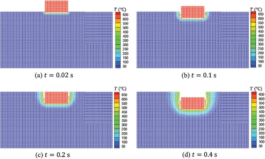
Figure 20:Temperature contours and ablated shapes when Tc0=1800°C at time t=0.02 s,0.1 s,0.2 s and 0.4 s,respectively
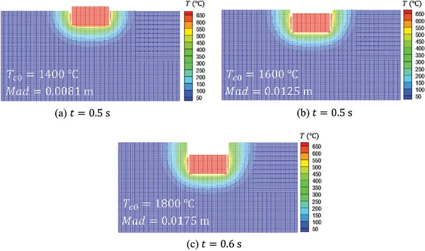
Figure 21:Temperature contours and ablated shapes with the maximum ablated depth(Mad)for Tc0=1400°C,1600°C and 1800°C,respectively
6.4 Lower Head of RPV Ablated by a Core Melt
Finally,the ablation process of the lower head of the RPV heated by core melt,which is simplified from the nuclear engineering problems,is investigated[15].Fig.22a shows the two-layer structure of melt core in the lower head of the RPV,in which the radius of the inwall isR=2 m and the thickness of the wall isδV=0.2 m.The thicknesses of the molten UO2and molten metal areHU=1.325 m andHM=0.270 m,respectively.The material parameters of the RPV are:k=25.5 W/(m ·K),c=740 J/(kg ·K),ρ=6890.0 kg/m3and the critical melting temperature is=1600 K.For the initial and boundary conditions,the initial temperature isT0=373 K and the temperature of the outer wall is fixed byT1=373 K.Moreover,a non-uniform heat fluxq(θ)is imposed on the moving inwall of the RPV,in which the distribution ofq(θ)is plotted in Fig.22b.For the sake of the computational cost,only half of the symmetric RPV is utilized for the numerical simulation.Then,the RPV is discretized into many uniform material points,whose size is Δx=Δy=0.0025 m.The horizon of the material point isδ=3.0Δx.The step for the time integration is chosen as 1.0×10⁻²s and the total time is 2000.0 s.Fig.23 shows the profile of the moving inwall of the RPV caused by the thermal ablation,from which it can be seen that the ablation occurs at the region imposed a larger heat source and the minimum thickness of the RPV becomes smaller and smaller along with the thermal ablation process.Moreover,Fig.24 presents the temperature contours and ablated shapes of the RPV at timet=200 s,600 s,1000 s,1200 s,1600 s and 2000 s,respectively.The ablated shapes obtained by the present method are similar with those obtained by the finite element method[15].Consequently,the present peridynamic method is valid and effective for the evaluation of the ablation of the RPV heating by a core melt.

Figure 22:Illustration of the RPV model:(a)Two-layer structure of melt core and(b)heat flux imposed on the inwall
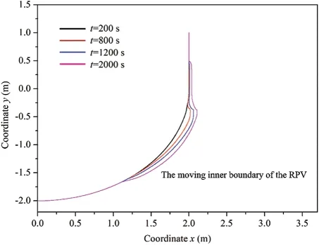
Figure 23:Profile of the moving inwall of the RPV caused by the thermal ablation
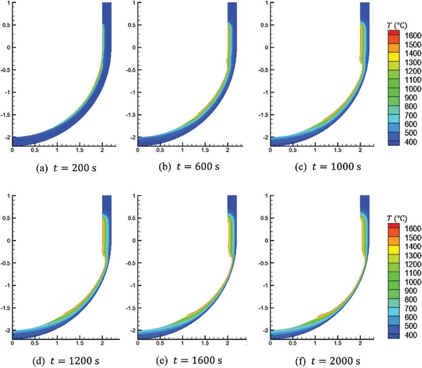
Figure 24:Temperature contours and ablated shapes of the RPV at time t=200 s,600 s,1000 s,1200 s,1600 s and 2000 s,respectively
7 Conclusions
This paper presents a nonlocal peridynamic method for the evaluation of the thermal ablation in metal under high temperature.Firstly,the peridynamic formulation for the transient heat conduction problem is derived based on Taylor’s expansion technique.To simulate the thermal ablation problem,whose geometry is changed,a simple and efficient moving boundary model in the peridynamic framework is proposed by introducing a scalar field to describe the ablated states of material points.In addition,on the basis of the automatic non-interpenetration properties of the peridynamic method,an effective contact algorithm is suggested to determine the contact relationship between the ablated system and the additional heat carrier.Furthermore,the corresponding computational procedure is given out in detail.Finally,several representative numerical examples are taken into account.These results obtained by the present method fit well with the reference solutions,which demonstrates the validity and accuracy of the present method.Moreover,the present peridynamic method can be extended to analyze the coupling thermo-,deformation-,ablation-and fracture problems in the future.
Funding Statement:This work was supported by the National Natural Science Foundation of China(No.12102416).
Conflicts of Interest:The authors declare that they have no conflicts of interest to report regarding the present study.
 Computer Modeling In Engineering&Sciences2023年3期
- Computer Modeling In Engineering&Sciences的其它文章
- A Consistent Time Level Implementation Preserving Second-Order Time Accuracy via a Framework of Unified Time Integrators in the Discrete Element Approach
- A Thorough Investigation on Image Forgery Detection
- Application of Automated Guided Vehicles in Smart Automated Warehouse Systems:A Survey
- Intelligent Identification over Power Big Data:Opportunities,Solutions,and Challenges
- Broad Learning System for Tackling Emerging Challenges in Face Recognition
- Overview of 3D Human Pose Estimation