
Vibration and Sound Radiation of Cylindrical Shell Covered with a Skin Made of Micro Floating RaftArrays Excited by Turbulence
2023-01-21 08:05DanZhaoQiongWuMinyaoGanKeLiWenhongMaQunWuLiqiangDongandShaogangLiu
Dan Zhao,Qiong Wu,Minyao Gan,Ke Li,Wenhong Ma,Qun Wu,Liqiang Dong and Shaogang Liu
1College of Mechanical and Electrical Engineering,Harbin Engineering University,Harbin,150001,China
2Shanghai Marine Equipment Research Institute,Shanghai,200031,China
ABSTRACT To reduce the vibration and sound radiation of underwater cylindrical shells,a skin composed of micro floating raftarrays and a compliant wall is proposed in this paper.A vibroacoustic coupling model of a finite cylindrical shell covered with this skin for the case of turbulence excitation is established based on the shell theories of Donnell.The model is solved with the modal superposition method to investigate the effects of the structural parameters of micro floating raftelements on the performance of reducing vibration and sound radiation of the cylindrical shell of this skin.The results indicate that increasing the stiffness ratio,damping ratio,mass ratio,or decreasing the interval between micro floating raftelements can improve the vibration and sound radiation reduction performance of this skin over the frequency range 0~2000 Hz.Moreover,the mean quadratic velocity level and sound radiation power level of the finite cylindrical shell with this skin can be reduced by 12.00 dB and 9.65 dB respectively compared to the finite cylindrical shell with homogeneous viscoelastic coating in the frequency range from 0~2000 Hz,implying a favorable performance of this skin for reducing the vibration and sound radiation of cylindrical shells.
KEYWORDS Finite cylindrical shell;vibration and sound radiation;noise reduction;turbulent pulsating pressure;micro floating raft
1 Introduction
The vibration and sound radiation of underwater cylindrical shells are always the main research contents in mechanics and acoustics because the cylindrical shell is the main structure of the great majority of underwater vehicles [1].In order to reduce the vibration and sound radiation of the cylindrical shell,active vibration control[2,3],dynamic absorbers[4],circumferential ribs[5],lateral reinforced plates [6] and compliant layer [7,8] have been employed in the past.Among them,a compliant layer is widely used due to the stronger plasticity in structural design and lower cost in manufacturing.Laulagnet et al.[9]presented a mathematical model in order to investigate the sound radiation from a finite cylindrical shell covered with a compliant layer,indicating that a compliant layer with reasonable stiffness can reduce the radiated power in a large frequency domain.Liu et al.[10]focused on the vibration and acoustic radiation of a finite cylindrical shell,which is partially covered with circumferentially laid compliant layers and immersed in an infinite heavy fluid medium.It is found that the axisymmetry of the coatings has an effect on the radiated power of the partially covered shell.Huang et al.[11]presented an optimal design of acoustic coating with complex-shaped cavities based on a combining use of the analytical vibroacoustic model and a differential evolution algorithm to explore the better performance of sound radiation reduction.As can be seen,the compliant layer is an effective method to control the vibration and sound radiation of cylindrical shells and the optimal design of the compliant layer is one of the major research directions.
A floating raft isolation system has been widely applied to reduce the multi-point vibration of power units inside the ship[12–14].Li et al.[15]analyzed the power flow of a floating raft isolation system by using the Green function,demonstrating a satisfactory vibration-reduction effect of the floating raft system.Liu et al.[16] studied the influence of the floating raft isolation system on the vibration characteristics of the marine pump,indicating the maximum vibration intensity of the pump is reduced by 88% after installing the floating raft damping system.Li et al.[17] focused on the effects of the geometric parameters of a floating raft on isolation performance.The results show that the structural parameters of middle mass have an impact on isolation performance.Fang et al.[18]investigated the vibration reduction characteristic of the floating raft with a periodic structure,demonstrating the same quality of the periodic floating raft has a better isolation effect than that of the single floating raft.
Considering the limitations of the current vibration and sound radiation reduction technology and the similarity between the multi-point excitation on the floating raft system and the turbulence excitation,a skin made of micro floating raft arrays and compliant layer(will be abbreviated as floating raft skin in following) is proposed.The structure is shown in Fig.1,where the upper layer is the compliant wall and the lower layer is micro floating raft arrays.

Figure 1:The structure of a skin made of micro floating raft arrays
Consisting of a compliant wall and micro floating raft arrays,the floating raft skin has several adjustable parameters such as stiffness ratio and damping ratio.It is expected to have a better performance in controlling turbulent coherent structures,so as to reduce vibration and sound radiation of underwater cylindrical.The micro floating raft element not only can absorb and attenuate elastic wave directly,but also can form different periodic structure due to its adjustable interval and size,so that changing the noise suppression bands and bandwidths of the floating raft skin and realizing the function of reducing vibration and sound radiation.The proposal of this novel skin not only is helpful to improve the vibration and sound radiation performance of underwater cylindrical,but also makes a beneficial exploration in related theory and application.
The remainding part of this paper is organized as follows.In Section 2,the mathematical model of a finite cylindrical shell covered with floating raft skin is established based on the shell theories of Donnell and it is solved with modal superposition method.In Section 3,the relationship between the performance of the floating raft skin to reduce the vibration and sound radiation of cylindrical shells and the structural parameters of micro floating raft elements is investigated.The difference in the performance for reducing vibration and sound radiation of cylindrical shells between the floating raft skin and homogeneous viscoelastic coating is also discussed in Section 3.Finally,the conclusion of this paper is drawn in Section 4.
2 Modelling and Solving
2.1 Mathematical Modelling
In order to investigate the vibration and the sound radiation performance of the floating raft skin,a mathematical model of the cylindrical shell covered with the floating raft skin should be established.Here,the cylindrical shell covered with the floating raft skin is shown in Fig.2,whose thickness divided by radius is less than 5%,is thin with radiusr2and lengthL;lis the distance between any two micro floating raft elements.Between the compliant and the cylindrical shell,there is an internal fluid.Among them,the micro floating raft element consists of upper and lower spring-damping elements and a middle mass.This shell is submerged in finite external fluid domain in which the sound velocity isc0and the fluid density isρ0,wherehis the thickness of the compliant wall,r1is the radius of the compliant wall.
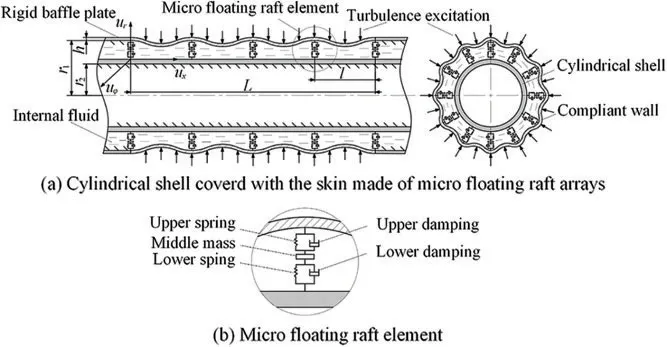
Figure 2:Cylindrical shell covered with the floating raft skin
Based on the shell theories of Donnell[19],the vibration equation of the compliant wall can be set up
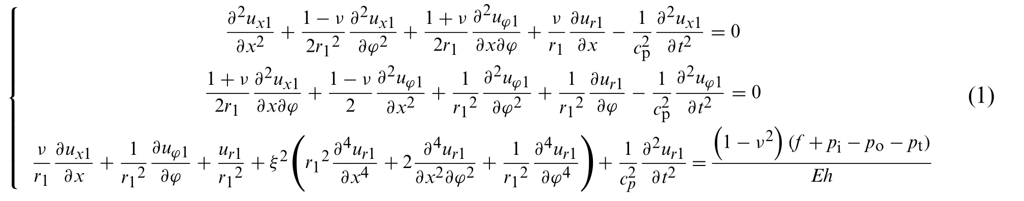
whereux1,uφ1andur1are the axial,circumferential and radial displacements of the compliant wall respectively withx,φandrare the axial,circumferential and radial directions,respectively;νis the Poisson’s ratio of the compliant wall,ρis the mass density of the compliant wall,Eis the Young’s modulus of the compliant wall;tis the time;f,pi,po,ptare the support force of micro floating raft array,the radial pressure of the internal fluid,the radial pressure of the external fluid and the excitation of turbulence,respectively;ξ2=is the thickness factor of the compliant wall;cp=is the longitudinal wave velocity of the plate expanded by the compliant wall.
The displacements of the compliant wall are expanded with the modal expansion method,as follows:

wheremandnare the axial and circumferential mode number,respectively;km=;e-iωtis harmonic time factor with the imaginary unitiand the circular frequencyω.
Similarly,the support force of micro floating raft array,the radial pressure of the internal fluid,the radial pressure of the external fluid and the excitation of turbulence are expanded,as follows:
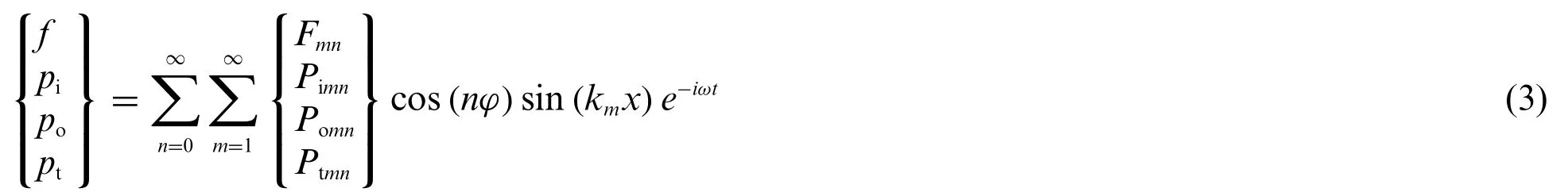
whereFmn,Pimn,PomnandPtmnare undetermined coefficients.
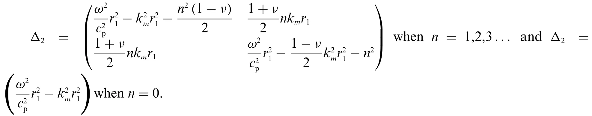
Substituting Eqs.(2) and (3) into Eq.(1),the modal vibro-acoustic coupling equation of the compliant wall is formulated as follows:

where the matrix Δ1is shown as follows:
Solving the Eq.(4)by separating variable methods leads to the radial modal vibration equation of the compliant wall

To attain the numerical solution of Eq.(5),the coefficientsFmn,Pimn,PomnandPtmnwhich can be expressed as follows need to be solved firstly
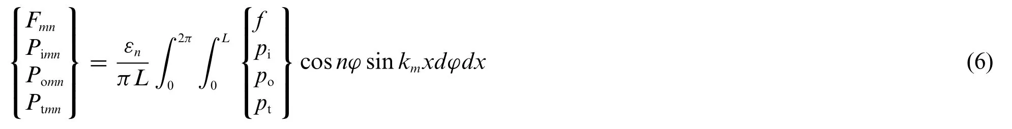
whereεnis the Neumann factor,whenn=0,εn=1;whenn≥1,εn=2.
The bearing condition of thej-thcompliant wall element is shown in Fig.3,wheref j,pji,andmean the support force of micro floating raft array,the radial pressure of internal fluid,the radial pressure of the external fluid and the excitation of turbulence acting on thej-thcompliant wall element,respectively;k1,c1,m2,k2andc2are the stiffness of upper spring,the coefficient of upper damping,the middle mass,the stiffness of lower spring and the coefficient of lower damping,respectively;m1=2πr1hlρis the mass ofj-thcompliant wall element.
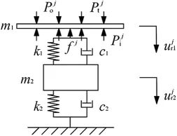
Figure 3:The j-th compliant wall corresponding to micro floating raft element
The dynamic equation of thej-thcompliant wall element is
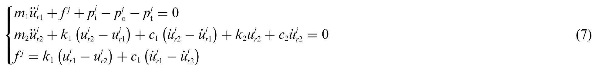
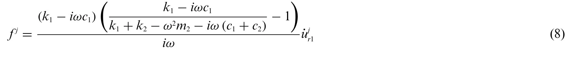
The support force of micro floating raft element can be solved according to Eq.(7)
The support force of the micro floating raft array equals the sum of the support forces of micro floating raft elements,as shown as follows:

whereTlis the number of micro floating raft elements.
Combining Eq.(9) with Eq.(6),the coefficient of the support force of the micro floating raft array is

whereZfis the additional impedance caused by micro floating raft array,as shown as follows:

The compliant wall vibrates due to the excitation of turbulence,leading to the vibration of the internal fluid.The radial pressure of internal fluid satisfies the Helmholtz equation[20].

It can be seen from Eq.(3)

Substituting Eq.(13) into Eq.(12),the formal solution ofPimncan be obtained by using the separated variable method.

wherekr=JnandYnare the first kind and the second kind of Bessel function;InandKnthe first kind and the second kind of modified Bessel function;AnmandBnmare undetermined coefficients.
The boundary condition of the internal fluid radial pressure is shown as followes:
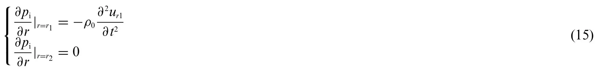
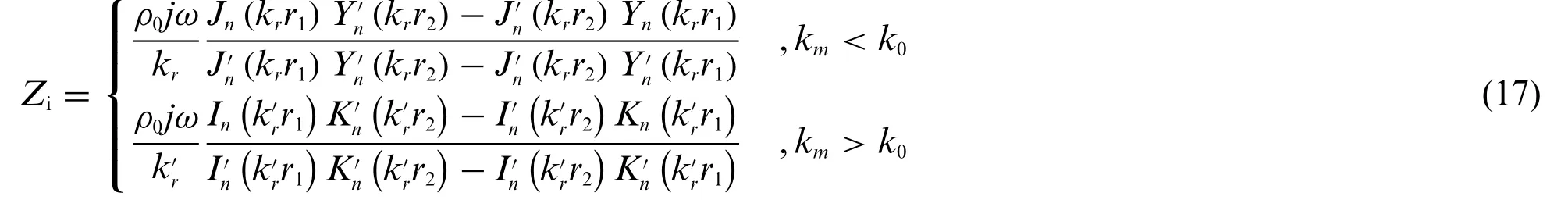
Substituting Eq.(14) into Eq.(15) can we solve the coefficientsAnmandBnm,leading to the coefficientPimn

whereZiis the radiation impedance of internal fluid.
The radial pressure of the external fluid at(r,φ,x)also satisfies the Helmholtz equation

By the method of separation of variables and the x-dimensional Fourier transform,the equation of(r,φ,k)can be obtained


The radiation pressure of external fluid satisfies the boundary condition

Substituting Eq.(20) into Eq.(21),and carries on the Fourier transform treatment,soPomnis solved

whereZqmnis the mutual radiation impedance between (q,n) and (m,n) order modes,as shown as follows:

The turbulent excitation is expressed by Corcos model

where the specific parameter can be found in Ko[21].
Inverse Fourier transform is used fordefined by(24),and then coefficientPtmnis solved

Substituting Eqs.(11),(17),(23)and(25)into Eq.(5),the modal velocity solution of the compliant wall is obtained.Furthermore,the mean quadratic velocity and the sound radiation power of the compliant wall can be represented as
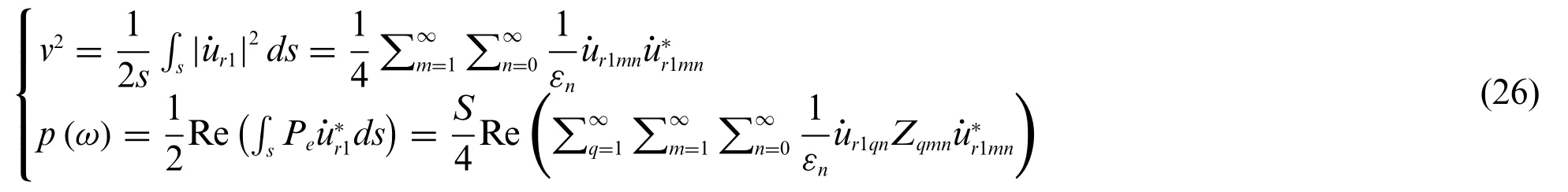
whereSis the surface area of the compliant wall;“||”means modulus of complex number;is the conjugate of ˙ur1mn;“Re()”means taking the real part of complex numbers.
The mean of quadratic velocity level and sound radiation power level is defined as
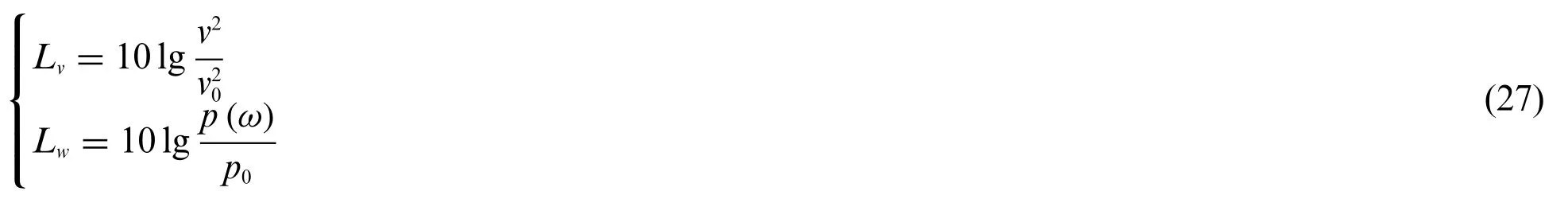
wherev0=5×10⁻⁸m/s;p0=1×10-12w.
2.2 Convergence Study of the Axial and Circumferential Mode Number
Figs.4a and 4b show the curves of the mean quadratic velocity level and the sound radiation power level with the frequency under different truncation values of the axial mode number,respectively.It can be seen thatm=15 is enough to guarantee the accuracy in the frequency range from 0 to 2000 Hz.
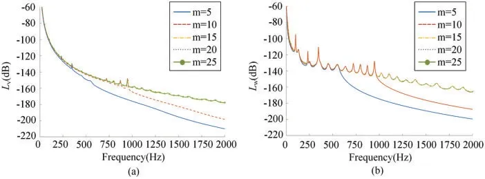
Figure 4:Result of the mean quadratic velocity level and the sound radiation power level under different truncation values of the axial mode number
Figs.5a and 5b show the curves of the mean quadratic velocity level and the sound radiation power level with the frequency under different truncation values of the circumferential mode number,respectively.It could be noted thatn=20 is enough to guarantee the accuracy in the 0–2000 Hz scope.
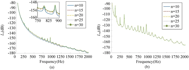
Figure 5:Result of the mean quadratic velocity level and the sound radiation power level under different truncation values of the axial mode number
2.3 Validation of the Algorithm
In order to verify the accuracy of the algorithm,the sound radiation power level in Guo et al.[22]is calculated by using our method.The parameters used are shown in Table 1.
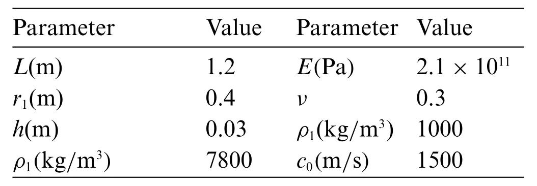
Table 1:Parameters used to verify the accuracy of the algorithm
The excitation force concentrates at the locations ofφ=0 andx=L/2 with 1N amplitude.Mutual coupling is ignored,and onlyq=mitems are considered.The calculated frequency band is 0–2000 Hz.The result is shown in Fig.6.
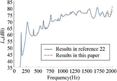
Figure 6:Result comparison with[22]
I n Fig.6,we can find the curve trend of this paper is in good agreement with Guo.The error in the high frequency band is caused by the different shell motion theories used in the two papers.The shell theories used in Guo are proposed by Flugge,but Donnell shell theories are used in this paper.
3 Results and Discussion
The curves of mean quadratic velocity and sound radiation power with the coefficients of the interval micro floating raft elementsα=l/h,stiffness ratioβ=k1/k2,damping ratioγ=c1/c2and the mass ratioδ=m2/m1is obtained in this part.The current velocity of water is 5m/s.Other basic parameters used are shown in Table 2.
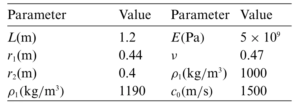
Table 2:Parameters of the cylindrical covered with floating raft skin
3.1 The Effect of Micro Floating Raft Element Interval on the Vibration and Sound Radiation Reduction Performance of the Floating Raft Skin
Increase inαfrom 2 to 6 and other coefficients areβ=0.1,γ=0.5 andδ=1 in Fig.7.
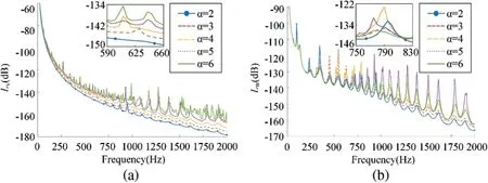
Figure 7:The influence of different micro floating raft element interval on(a)mean quadratic velocity level and(b)sound radiation power level
From Fig.7a,the value of the mean quadratic velocity levelLvincreases with the growth of the interval of micro floating raft elementsα.This is because the modal velocity ˙ur1mnwhich decides the value of the mean quadratic velocity level increases when the interval of micro floating raft elements increases.From Fig.7b,the value of the sound radiation power levelLwincreases first and then decreases when the interval of micro floating raft elements increases.The result happens because the sound radiation power level depends on both the modal velocity ˙ur1mnand the mutual radiation impedanceZqmn.While with the increase of the interval of micro floating raft elements,the number of circumferential modesncorresponding to a formant decreases,which can be seen in Fig.8,leading to the decrease of the mutual radiation impedanceZqmn.It can be concluded that the floating raft skin will perform better in the case of lowering the interval of micro floating raft elements.

Figure 8:The modes of one formant corresponding to different micro floating raft element interval
3.2 The Effect of Stiffness Ratio on the Vibration and Sound Radiation Reduction Performance of the Floating Raft Skin
The stiffness ratioβis increased within the range of 0.2~1.0,the other coefficients areα=2,γ=0.5 andδ=1.The result is shown in Fig.9.

Figure 9:The influence of different stiffness ratio on(a)mean quadratic velocity level and(b)sound radiation power level
It could be noted in Fig.9 that there is no obvious difference in the trend of the curves of the mean quadratic velocity level and the sound radiation power level with various stiffness ratio,indicating that the vibration and sound radiation reduction performance of the floating raft skin is hardly changed by changing stiffness ratio.The reason behind these results is that the modal velocity is decided by the sum of the impedances,but only the imaginary part of the additional impedance of micro floating raft arrayZf,which is far less than the imaginary part of other impedances,is affected by stiffness ratio.However,there are differences in the position and height of the peaks of the curves of the mean quadratic velocity level and the sound radiation power level with various stiffness ratio because the skin resonance characteristics changes when the impedance changes.
3.3 The Effect of Damping Ratio on the Vibration and Sound Radiation Reduction Performance of the Floating Raft Skin
Selectingα=2,β=0.6 andδ=1,increasing damping ratioγover the range of 0.1~0.9,the mean quadratic velocity level and sound radiation power level are calculated in Fig.10.
As shown in Fig.10a,the mean quadratic velocity level decreases with the increase of the damping ratioγ.This is because,with the increase of damping ratio,the modal velocity decreases due to the growth of the additional impedance of the micro floating raft array.It can be seen in Fig.10b that the sound radiation power level increases first and then decreases in low frequency band with the increase of damping ratio.The reason is that when damping ratio increases,the number of circumferential mode(m,n)corresponding to the same formant increase,which can be seen in Fig.11,leading to the decrease of the mutual radiation impedance.However,the sound radiation power level decreases continuously with the increase of the damping ratio in the high-frequency band.The reason can be described as that the influence of the mutual radiation impedance in high-frequency analysis can be ignored.Because in the high-frequency band,the influence of the damping ratio on the mutual radiation impedance becomes weaker.To summarize,selecting a higher damping ratio contributes to making the floating raft skin perform better in reducing the vibration and sound radiation of the cylindrical shell.
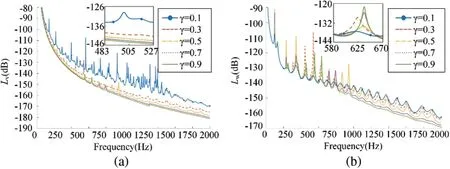
Figure 10:The influence of different damping ratio on(a)mean quadratic velocity level and(b)sound radiation power level
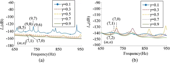
Figure 11:The modes of one formant corresponding to different damping ratio
3.4 The Effect of Mass Ratio on the Vibration and Sound Radiation Reduction Performance of the Floating Raft Skin
Whenα=2,β=0.6 andγ=0.7,increasing mass ratioδfrom 2 to 10.Fig.12 gives the mean quadratic velocity level and sound radiation power level.
It can be seen from Fig.12,the mean quadratic velocity level and the sound radiation power level decrease with the increase of mass ratioδ,and the peaks of the curves shift right.This performance indicates that increasing mass ratio is helpful to enhance the vibration and sound radiation reduction performance of the floating raft skin and increase the resonance frequency.The reason is that the additional impedance of micro floating raft array increases when mass ratio increases,so that the modal velocity decreases.Hence,both the mean quadratic velocity level and the sound radiation power level decrease.
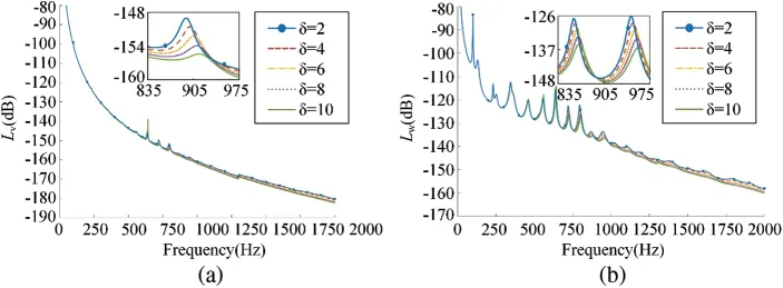
Figure 12:The influence of different mass ratio on (a) mean quadratic velocity level and (b) sound radiation power level
3.5 Comparison in Vibration and Sound Radiation Reduction Performance with Homogeneous Viscoelastic Coating
In order to further analyze the vibration and sound radiation reduction performance of the floating raft skin,selecting parameters:α=2,β=0.6,γ=0.7 andδ=6,the mean quadratic velocity level and sound radiation power level of the floating raft skin are calculated and compared with homogeneous viscoelastic coating[23],shown in Fig.13.
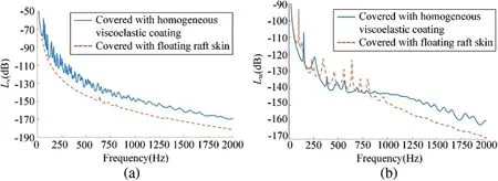
Figure 13:The vibration and sound radiation performance of two kinds of coating
As shown in Fig.13,in the frequency range with 0–2000 Hz,the average mean quadratic velocity level of the floating raft skin is reduced by 12.00 dB and the average mean quadratic velocity level of the floating raft skin is reduced by 9.65 dB compared with homogeneous viscoelastic coating.This shows that the floating raft skin perform better in vibration and sound radiation reduction than the homogeneous viscoelastic coating in the frequency range from 0 to 2000 Hz.
4 Conclusions
In this paper,a skin made of micro floating raft arrays is proposed,which is consisted of a floating raft system and a compliant wall.A mathematical model of the cylindrical shell covered with the floating raft skin is established,and the influence of various structural parameters on the compliant wall in the vibration and sound radiation of the shell is illustrated.The results show that increasing the stiffness ratio,damping ratio,mass ratio or decreasing the micro floating raft element interval can improve the vibration and noise reduction performance of the micro floating skin.Moreover,the floating raft skin can reduce the mean quadratic velocity level and sound radiation power level by 12.00 dB and 9.65 dB more respectively compared to the counterpart with homogeneous viscoelastic coating,leading to a favorable performance for reducing the hydrodynamic noise.
Funding Statement: The work is supported by the National Natural Science Foundation of China(Grant Nos.51775123,52075111)and the Fundamental Research Funds for the Central Universities(Grant No.3072021CF0702).
Conflicts of Interest:The authors declare that they have no conflicts of interest to report regarding the present study.
 Computer Modeling In Engineering&Sciences2023年3期
- Computer Modeling In Engineering&Sciences的其它文章
- A Consistent Time Level Implementation Preserving Second-Order Time Accuracy via a Framework of Unified Time Integrators in the Discrete Element Approach
- A Thorough Investigation on Image Forgery Detection
- Application of Automated Guided Vehicles in Smart Automated Warehouse Systems:A Survey
- Intelligent Identification over Power Big Data:Opportunities,Solutions,and Challenges
- Broad Learning System for Tackling Emerging Challenges in Face Recognition
- Overview of 3D Human Pose Estimation