
Towards high-efficiency of hydrogen purification in metal hydride
2023-03-30 08:35KouaAlainJesusKouaJiahePengArramelArramelNengLi
Koua Alain Jesus Koua, Jiahe Peng, Arramel Arramel, Neng Li,d,*
a State Key Laboratory of Silicate Materials for Architectures, School of Materials Science and Engineering, Wuhan University of Technology, Hubei, 430070, China
b Shenzhen Research Institute of Wuhan University of Technology, Shenzhen, 518000, Guangdong, China
c Nano Center Indonesia, Jalen Raya PUSPIPTEK, South Tangerang, Banten, 15314, Indonesia
d School of Chemistry and Environmental Engineering, School of Environmental Ecology and Biological Engineering, Novel Catalytic Materials of Hubei Engineering Research Center, Wuhan Institute of Technology, Wuhan, 430205, China
Keywords:Hydrogen purification Metal hydride Discharge coefficient Lumped model simulation Carbon dioxide
A B S T R A C T Recent advancement on hydrogen (H2) retrieval in a mixture gas of H2/CO2 based on the metal hydride (MH)technique has attracted numerous interests.In this work,we implement the lumped element model simulation to conduct a theoretical approach on the hydrogen purification process.The influence of orifice geometry and temperature of the tank, and inflow gas rate (fin) is investigated.The results show that the discharge coefficient(DC)is affected by the tank's orifice geometry.The orifice shape is increasing the value of DC,as a result,the CO2(impurity) outflow rate heightens during the venting process and thereby promoting to obtain a high hydrogen purity.By overcoming the exothermic/endothermic effect in the absorption/desorption step and a proper fin selection, we find an improvement in the hydrogen storage capacity (wt%) into MH and consequently the hydrogen recovery rate increases.A sharp improvement in orifice geometry and thermal conditions of the tank,and fin enhances the main targeted results (hydrogen purity and recovery rate)and ensures the proper operation of the MH technique.
1.Introduction
The search for highly efficient energy production sources is envisaged as a solution to the global energy deficit with critical criteria such as energetically feasible and non-polluting solutions.Renewable energies are perceived to be the perfect candidates for energetic and environmental challenges [1-3].The hydrogen vector, satisfying the aforementioned criteria and being able to be coupled with electricity via fuel cell applications appears as the best candidate for this direction[4-11].The advent of MHs that can densely store and remarkably purify hydrogen has strengthened the motivation to consider hydrogen as a promising energy vector [12-16].The chemical reaction which describes the formation of MHs iswhere M is a metal or alloy and MHxis the MH.The heat source represented by ΔH needs to be controlled for high-performance hydriding and dehydriding processes [17-23].In this regard,methods consisting of cooling/heating the MH bed are used for enhancing heat transfer and promoting rapid absorption/desorption[24-29].In the case where the heating is carried out by a fluid, the increase in the convection heat transfer coefficient h improves the desorption performance [30].Cooling fins [28,31], helical coil heat exchangers[32,33]and metal foams can also be used as cooling/heating systems and many articles reported that aluminum foam gives better results among the metal foams [34-38].
Thermal conductivity is a key parameter in MH study and it can be used as a physical parameter to significantly improves heat transfer[39,40].A large volume of the gas space obstructs the reaction rates as it increases the heat convection in the expansion volume and the thermal resistance[27,41].Busquˊe et al.reported that a low absorption rate coefficient Cahelps to decrease the tank's temperature and promotes the absorption[42]while the desorption process is more effective when the desorption rate coefficient Cdincreases, and the desorption reaction enthalpy ΔH and the activation energy for desorption Eddecrease [43].The mathematical model simulation developed by Minko et al.is in agreement with the experimental data of the hydrogen purification process in a mixture of gases[44,45].Since then,simulation studies were used beforehand practical phases to verify the feasibility of the purification research plans.Talaganis et al.demonstrated that the lumped element model can be used as a simulation tool to conduct the purification process[46] and the parameters such as the supply pressure, the mass of the material, the ambient temperature and the overall heat transfer coefficient were identified as influencing the purification system[47].Pure hydrogen can be obtained from fossil fuels, biomass, and organic wastes with the metal hydride technique [48-52].In this case,other methods (membrane module, adsorbent method …) may be used beforehand to remove some poisonous substances(CO,H2O…) to MH.
MH technique for hydrogen purification necessitates three governing steps such as commons hydriding, dehydriding and the venting phase[14,46,47].The venting phase corresponds to the process to vent the impurity out of the tank to avoid hydrogen contamination during desorption.The purge of impurities appears as the key challenge that must be handled with great attention to obtain a high hydrogen purity.Additionally, a high hydrogen recovery rate is expected when the purification process is carried out successfully.In this study, a special MH system is used to achieve a selective purification of hydrogen from CO2.In this regard, lumped element model simulation used in Matlab/Simulink software was developed to evaluate the performance of the MH system for the hydrogen purification process.Once the model is confirmed with experimental data, we investigate the tank's orifice geometry that might influence the purge of impurity because the orifice shape assigns a discharge coefficient (DC) to the mass outflow equation of the gases.Thus, MH tanks with different orifice shapes (different values of DC)are simulated to understand how they affect the hydrogen purification process.In order to recover a high amount of hydrogen gas as required during the current purification process, the improvement of hydrogen sorption is explored via the effect of finand thermal conditions on hydrogen storage capacity(wt%)and recovery rate.
2.Governing equations for the lumped model simulation
2.1.Mass conservation
LaNi5metal hydride is used to perform this simulation study.The mass of the metal hydride mMH(g),the solid material mass ms(g)which is the mass of all the LaNi5with no hydrogen, and the metal hydride reaction rate per mass r (gMH/gs/s) are used to express the mass conservation equation for the metal hydride as:
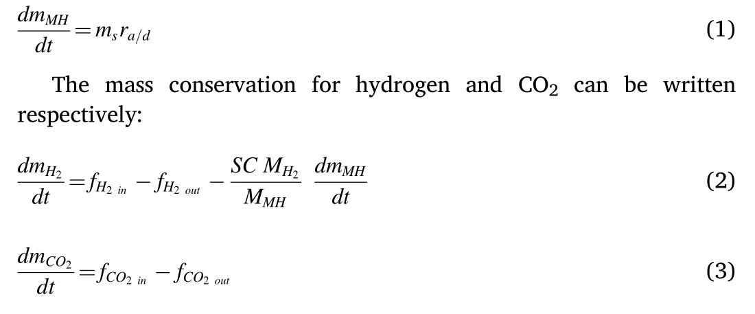
where mH2is the hydrogen mass and mCO2is the mass of CO2.f is the net mass flow, SC is the stoichiometric coefficient, and MH2, MMHare the molecular weights for hydrogen and the metal hydride respectively.
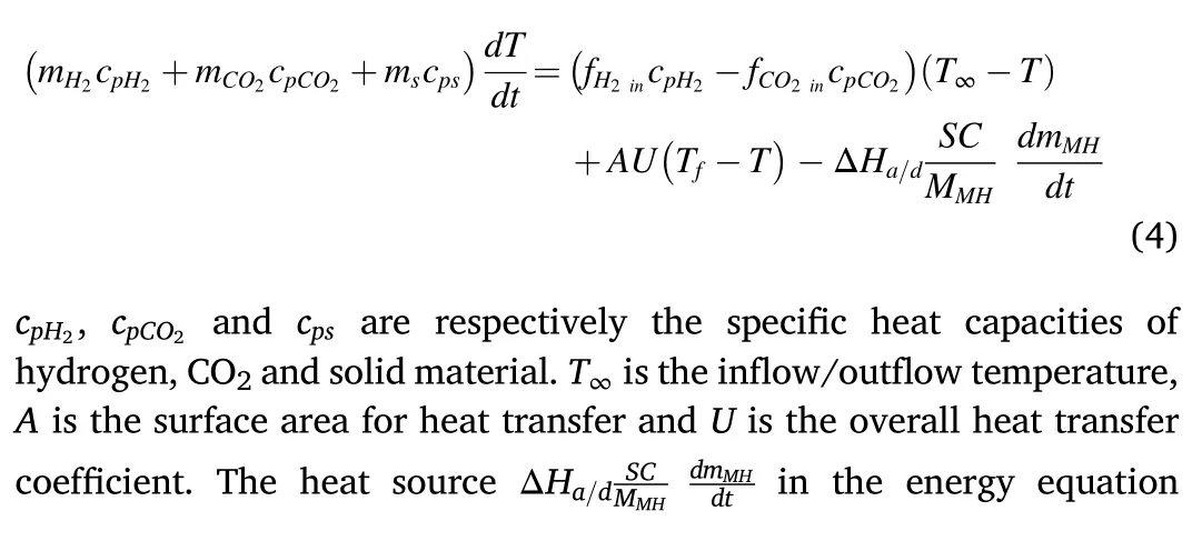
2.2.Energy conservation
The energy equation is:
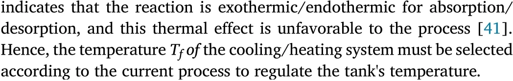
2.3.Reaction kinetics rate and equilibrium pressure
The reaction kinetics for absorption (ra) and desorption (rd) are expressed as follows
where ΔS is the reaction entropy,sl is the plateau slope coefficient which is equal to 0.13 for LaNi5material[53],and P0is the reference pressure(1 bar).
2.4.Auxiliary equations
CO2and Hydrogen are considered ideal gases and obey the following ideal gas law.
where PCO2,and PH2are the partial pressures of CO2and H2respectively.Vgis the volume of the gas space.The CO2mass concentration in the mixture gas was fixed at 2.15%.The relationship between the mass flow rates of CO2and hydrogen is described by the following equation:
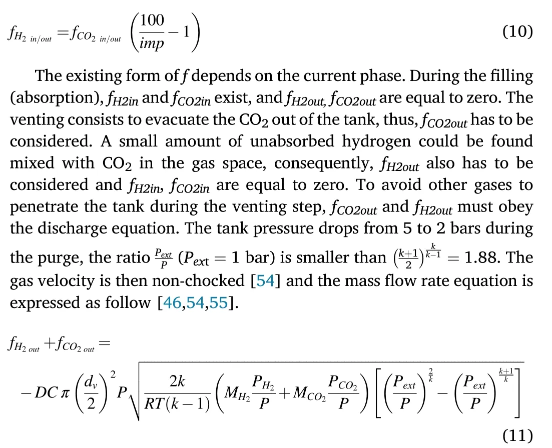
Once CO2is completely evacuated at the end of the venting step,pure hydrogen can be desorbed and fH2outhas to be considered while fH2in,fCO2inand fCO2outare equal to zero.The mass flow f in each stage of theprocess forms a matrix summarized in Table 1.

Table 1 Matrix for the purification flow rate.
3.Results and discussions
3.1.Lumped model simulation for hydrogen purification
Our lumped model simulation result is in agreement compared to the work of Talaganis and co-workers[46], as evidenced in Fig.1 based on the findings,the tank's temperature rises from 302.5K to 315K in 1986s due to the exothermic effect of the absorption process.The venting step follows the absorption by an opening of the evacuation valve to remove the impurity.The temperature suddenly dropped to 303.1K as the venting step reduces the inside pressure of the tank.The endothermic effect of the desorption process maintains the dropping of the temperature to the value of 301.1K before rising under the effect of the ambient temperature.The uprising temperature during absorption increases as well as the equilibrium pressure to 4 bars.The sudden drop in the temperature during venting lowers the equilibrium pressure from 4 to 2.2 bars.The equilibrium pressure reaches its lowest value at 2.1 bars during the early desorption process because of the endothermic effect,before it gradually increases due to the influence of the ambient temperature.Fig.1a and b shows the evolution of the temperature and the equilibrium pressure respectively.
Fig.1c illustrates that the hydrogen diffusion into the MH increases the CO2concentration in the gas space.The venting process evacuated the CO2from the tank,therefore the impurity drops from its highest value at the end of absorption(80%)to ~0 (at approximately 5.80 × 10⁻⁷%and below,the impurity is enough small and does not affect the hydrogen purity).The entire CO2is successfully evacuated from the tank at the end of the venting, consequently, no impurity exists in the tank during the desorption phase.Fig.1d shows an increase in the MH mass when the hydrogen gas diffuses into it and a reduction is occurred during hydrogen desorption.The respective mass of CO2and hydrogen are presented in Fig.1 e-f, they appeared to increase during filling and inversely drop during the venting phase.At the end of the venting step,the CO2mass is equal to 0 as no CO2exists in the tank while the hydrogen mass inside the tank is equal to 0.003 g.The partial pressures of hydrogen and CO2during the filling procedure are increased to 4.2 bars and 0.8 bars respectively.At the end of venting,PH2is equal to 2 bars and PCO2is equal to 0 as evidenced in Fig.1g and h.The total pressure(Fig.1i)is the sum of PH2and PCO2.The values of the parameters used in this simulation are listed in Table 2.
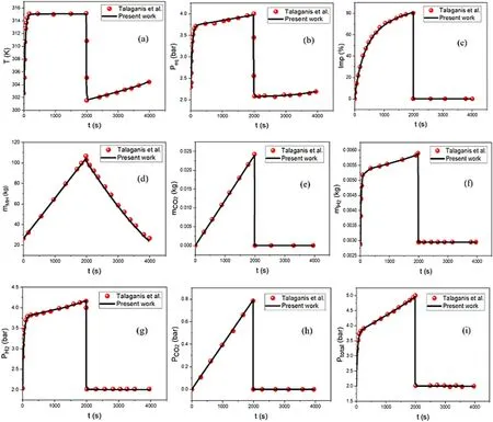
Fig.1.Model confirmation with experimental data.
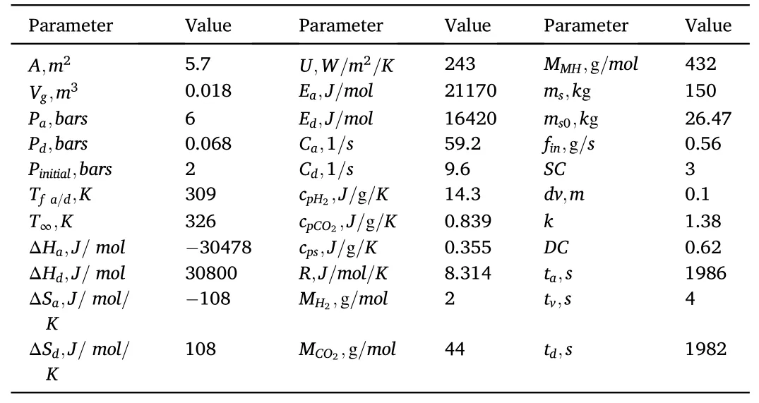
Table 2 Values of parameters used in the purification process [46].
3.2.Influence of the tank's orifice geometry on hydrogen purity
Many activity sectors such as optical fiber, rocket propulsion, fuel cells and so on require high-quality hydrogen for their performances.Hydrogen purity is therefore a key feature in the resolution as a new energy vector in high performance of hydrogen production.During the hydrogen purification process by the MH technique, the tank's orifice geometry assigns a discharge coefficient (DC) to the gas outflow rate equation and could influence the hydrogen purity.Actually, DC is a coefficient that depends on the tank's orifice shape,and it is introduced into equation (11) to correct the deviations between prediction and experimental measurement of flow conditions.Based on the lumped element model, we investigate the impact of the tank's orifice geometry on hydrogen purity through a numerical simulation involving different values of DC.Fig.2 below shows the orifice shapes used in this simulation and their corresponding values of DC[56-59].
This part of the simulation concerns the venting process(1986s-1990s)which is a decisive step for hydrogen purity.Indeed,the venting step consists to open the tank via its orifice to vent all impurities from the gas space to avoid hydrogen contamination when it is desorbed.The impact of the tank's orifice shape on hydrogen purity is shown in Fig.3.The simulation results highlight that the tank's orifice shape contributes to achieve a rapid and total evacuation of CO2by increasing the CO2flow rate from the tank outwards.Fig.3a and b shows that the outflow rates of the mixture gas(fgasesout=fH2out+fCO2out)and CO2gas(fCO2out)increase when DC increases.This could be explained by the fact that the tank's orifice shape assists to increase the velocity of the outgoing gas, as a result, the amount of the outgoing gas per unit area increases.This increase in fCO2outallows a fast evacuation of the CO2(reduces the venting time tv) and influences the hydrogen purity.In this regard, we perform the venting process for 1s,2s,3s and 4s durations with different values of DC,and the graph of the impurity is shown in Fig.3c.It can be seen that the incremental change in DC significantly reduces the impurity level within the tank.The venting time (tv) could be set at 3s for high values of DC (DC = 0.95, 0.96, 1) while the 4s purge used for this simulation is not enough to evacuate all the CO2from the tank for DC=0.5(at approximately 5.80×10⁻⁷%and below,the impurity is enough small and does not affect the hydrogen purity).This finding is useful for a rapid and complete impurity removal procedure.Therefore, the tank's orifice geometry plays a fundamental role in increasing the hydrogen purity and this parameter must be considered when performing the hydrogen purification process.
3.3.Parametric study for hydrogen storage system
The ability of MH to afford the hydrogen sorption process is considered a pointer factor of the effectiveness of the MH system.The hydrogen sorption is a linear function of hydrogen content in MH translated by hydrogen storage capacity (wt%) which increases/decreases during absorption/desorption.The improvement plan of wt% led to the investigation through a simulation of the effect of Tfand finon wt%.At this time,the absorption process is carried out until the MH is saturated.Our computation results are evidenced in Fig.4 and wt%is expressed by the following equation:
3.3.1.Effect of Tf
Fig.4a shows that during absorption, the tank's temperature T rises from its initial value 302.5K and it is slowed down under the influence of Tf.After 3250s(saturation time),the impurity removal process drops the temperature before gradually increasing during the desorption process due to the influence of Tf.The temperature variation depends on Tfand it is shown that the lower value of Tfcorresponds to the lower value of T.Fig.4b shows the related equilibrium pressure whose variation is impacted similarly as T with the change in Tf.The general consequence of the tank temperature effect is shown in Fig.4c.The results show that the temperature does not influence much wt%during absorption.This small increase of wt% with the change in T will be elucidated later.Once the MH is saturated,we proceed to the desorption of the absorbed hydrogen.We observe that the increase in the tank's temperature(with the increase of Tf)considerably decreases wt%which confirms that the increase in the temperature promotes hydrogen desorption.
3.3.2.Effect of fin
Through the outcome of this simulation in Fig.4d, finappears as an important parameter that strongly influences the sorption process.The increase in finincreases the ability of MH to absorb hydrogen and consequently the saturated time is faster.We can see for example that the saturation time for fin=0.85 g/s is about 3,2,1.5 times finequal to 0.3 g/s,0.45 g/s,0.56 g/s respectively,and also shorter than finequal to 0.65 g/s, 0.75 g/s.This fast saturation of MH rapidly initiates the desorption process and the absorbed hydrogen is promptly desorbed for practical applications.With regard to Fig.4c and d results,we notice that the tank's temperature,although stands as one of the main factors in the MH study,is not pointedly influencing the hydrogen absorption process with the values of Tfused in this simulation.finappears as the governing factor enhancing wt% during absorption, which explains the small increase of wt%with the change in T.The hydrogen sorption is summarized as wt%is improved by the increase in finwhile wt% is better when Tfincreases during desorption.
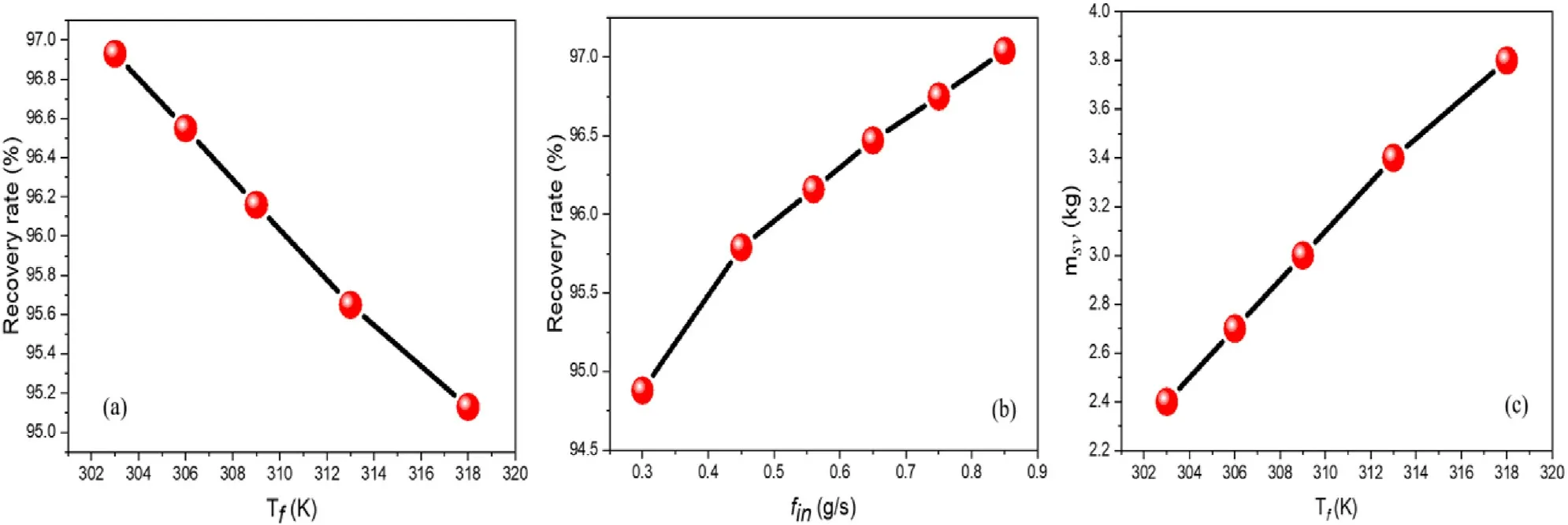
Fig.5.Influence of Tf and fin on the hydrogen recovery rate, and influence of Tf on msv.
3.4.Influence of inflow gas rate and thermal conditions on hydrogen recovery rate
The gas purification process must be performed without the significant loss of the targeted gas to be purified.Although we aspire for high hydrogen purity,a high recovery rate is also expected to be materialized during the overall purification stage.A high hydrogen purity and low recovery rate could make the MH technique not competitive with other purification methods.It was demonstrated in Fig.4 that finand the thermal effect inside the MH tank influence wt%,therefore,they could be decisive factors governing their impacts on the recovery rate.A parametric study for hydrogen recovery rate is carried out with a variation of Tfand fin,and the results are evinced in Fig.5.The measurement of the recovery rate is directed by the following equation.
Fig.5a and b shows that the hydrogen recovery gets a better rate when Tfdecreases while the increase in finincreases the recovery rate.Tfand finare parameters to be considered to recover a significant amount of hydrogen during the purification process.From equation(13)we notice that the measurement of the recovery rate is only based on the absorption and venting terms.A concern would remain in Fig.5a to understand the change in the recovery rate since Tfhas a small impact on wt% during absorption.This is because for favorable temperatures, after the saturation of MH, some amount of absorbed hydrogen is desorbed during the purge.Fig.5c shows the mass of the solid msv(msv= mMHaf- mMHvf)when Tfvaries during the venting.It can be seen that msvincreases with the increase in Tfwhich confirms that some amount of hydrogen is desorbed from MH during the purge.This desorption is higher when Tfincreases.Therefore, the main conclusion remains that with the decrease/increase in Tf/fin, the hydrogen recovery is proficient.Furthermore, for practical use of hydrogen, the trapped H2in the MH structure must be desorbed.At this time, the control of the desorption temperature is mandatory since it is demonstrated in Fig.4c that the low temperature prevents desorption.
4.Conclusion
The lumped element model simulation is demonstrated able to describe theoretically that a metal hydride system can be used for hydrogen purification in a mixture gas of H2/CO2.The optimization parameter of the purification system highlighted the impact of the MH tank's orifice geometry on the hydrogen purity, the inflow gas rate and the thermal effect on the hydrogen recovery rate.In the venting impurity simulation,we find that DC is increased with the tank's orifice shape.This reflects the condition in which a high amount of impurity is successfully extracted from the tank and leads to a high purity of hydrogen production.In addition,with an appropriate selection of Tfand fin,the hydrogen sorption process is improved and the hydrogen recovery has a better rate.The MH tank's orifice geometry,Tfand fingreatly contribute to the high performance of hydrogen production.
Declaration of competing interest
All authors declare no competing financial interest.
Acknowledgements
The work was supported by the Natural Science Fund for Distinguished Young Scholars of Hubei Province (Grant No.2020CFA087);Guangdong Basic and Applied Basic Research Foundation (Grant No.2022A1515011303); the Basic Research Program of Shenzhen (Grant No.JCYJ20190809120015163); the Central Government Guides Local Science and Technology Development Funds to Freely Explore Basic Research Projects (Grant No.2021Szvup106), and the Open Fund of State Key Laboratory of Silicate Materials for Architectures (Wuhan University of Technology) (Grant Nos.SYSJJ2016-05,SYSJJ2020-03).
Nomenclature
ΔH Reaction enthalpy, J/mol
ΔS Reaction entropy,J/mol/K
A Area of heat transfer,m2
cpSpecific heat capacity,J/g/K
E Activation energy,J/mol
f Net mass flow rate,g/s
Imp Impurity
m Mass,g
M Molecular weight,kg/mol
PeqEquilibrium pressure,Pa
r Reaction rate,gMH/gs/s
R Universal gas constant,J/mol K
sl Plateau slope coefficient
TfAmbient temperature,K
T∞Inflow/outflow temperature, K
U Overall heat transfer coefficient,w/m2K
VgVolume for gas phase in the reactor,m3
Subscripts
a Absorption
d Desorption
CO2Carbon dioxide
H2Hydrogen gas
in Inlet
MH Metal hydride
out Outlet
s Solid
v Venting
i Initial
f Final
 Progress in Natural Science:Materials International2023年3期
- Progress in Natural Science:Materials International的其它文章
- Research progress of composite cathode materials for Solid oxide fuel cells
- A review on solidification of alloys under hypergravity
- Improving mechanical properties of Mg-Sn alloys by co-addition of Li and Al
- Multi-stimuli bilayer hydrogel actuator for remotely controllable transportation of droplets
- The formation and temperature stability of microemulsion emulsified by polyoxyethylene ether surfactant
- Research advances on electrode materials for solid oxide electrolysis cells