
Effect of nitrile butadiene rubber hardness on the sealing characteristics of hydraulic O-ring rod seals
2024-01-24 06:01XiaoxuanLIBingqingWANGXudongPENGYuntangLIXiaoluLIYuanCHENJieJIN
Xiaoxuan LI, Bingqing WANG,, Xudong PENG, Yuntang LI, Xiaolu LI, Yuan CHEN, Jie JIN
Research Article
Effect of nitrile butadiene rubber hardness on the sealing characteristics of hydraulic O-ring rod seals

1College of Quality and Safety Engineering, China Jiliang University, Hangzhou 310018, China2College of Mechanical and Electrical Engineering, China Jiliang University, Hangzhou 310018, China3College of Mechanical Engineering, Zhejiang University of Technology, Hangzhou 310023, China
The nitrile butadiene rubber (NBR) hardness effect on the sealing characteristics of hydraulic O-ring rod seals is analyzed based on a mixed lubrication elastohydrodynamic model. Parameterized studies are conducted to reveal the mechanism of the influence of rubber hardness on the static and dynamic behavior of seals. The optimized selections of rubber hardness are then investigated under different conditions. Results show that the low hardness seal is prone to stress concentration due to the extrusion effect under high pressure conditions; it is also more prone to leaking. A high hardness seal can better prevent leakage by reducing film thickness but it will cause large frictional power loss and increase the probability of wear failure. The choice of low hardness is recommended to reduce friction with the premise that leakage requirements are met.
Nitrile butadiene rubber (NBR) hardness; Sealing characteristics; Optimized selection; O-ring seal
1 Introduction
As one of the most popular elastomeric seals, nitrile butadiene rubber (NBR) O-ring seals have been widely used in the fields of aerospace, railway transportation, and so on, due to their excellent performance such as easy processing, low cost, simple but reliable structure, and good oil-resistance, anti-wear, and heat-resistance (Lee et al., 2016; Zhang and Xie, 2018). In materials science, rubber hardness is an important mechanical property index for characterizing the ability of the material to resist permanent deformation (Feyzullahoğlu, 2015). At the same time, the seal is a self-tightening one that relies on its own deformation under the influence of interference fit and fluid pressure to establish the key contact zone with sealing functions. The rubber hardness directly determines the level of the contact force in these zones, ultimately affecting its function of preventing fluid leakage (Liang et al., 2019; Windslow and Busfield, 2019; Cheng et al., 2022). In addition, rubber hardness is also one of the important material parameters in the selection of elastomer seals in engineering practice. However, the influence of rubber hardness on sealing performance is currently unknown, resulting in a lack of effective basis for selection.
The work of Ucar and Basdogan (2018) on the uniaxial tensile test of natural rubber, showed that the elastic and shear moduli increase with an increase in the Shore A hardness. Nikas (2003, 2018) found that in the case of a rectangular elastomeric seal, the lower the elastic modulus of the seal, the easier it is for it to be squeezed into the clearance and the larger the deflection of the extruded part, as well as the larger the leakage rate and the coefficient of friction. Peng et al. (2021a) also showed that a seal with reduced elastic modulus due to the increase in ambient temperature would result in larger net leakage and friction force. However, there is still a lack of direct evaluation studies on the effect of hardness on seal behaviors or performances. Elhard et al. (2017) noted that the NBR O-ring seal with 90 Shore A hardness has better deformation resistance than that with 70 Shore A hardness and can adapt to situations with larger clearance and higher pressure but with smaller extrusion distance. Han et al. (2015) and Sukumar et al. (2019) showed by simulation that the von Mises stress and contact pressure of the seal increase with the increase of rubber hardness. Scheller and Baur (2021) showed, by static pressure leakage tests under vacuum conditions, that an O-ring seal with higher hardness will give lower gas leakage.
However, from the available literature, little work has been done on the study of the rubber hardness effect on sealing characteristics for hydraulic rod seals, which is an important index for engineering selection. In this paper, taking the NBR O-ring seal as an example, the hardness effect on the sealing characteristics under a series of static and dynamic operating conditions is studied, by using the proposed mixed lubrication model that is coupled with the constitutive model of rubber hardness. Furthermore, based on low friction and low leakage, the optimum ranges of rubber hardness under a wide range of operating conditions are also given and recommended.
2 Theoretical models
2.1 Geometrical model
The geometry of a hydraulic O-ring rod seal installed in housing is shown in Fig. 1, and the dimensions are determined in strict accordance with the standard GB/T 3452.3–2005 (GAQSIQ, 2005). According to the geometry of the seal without and with sealed pressure, as shown in Figs. 1a and 1b, the deformed behaviors of the seal under the assembly state and the pressurized state are schematically characterized. Generally, the contact zone where the seal makes contact with the moving rod is called the primary sealing zone, and the contact zone where the seal makes contact with the stationary housing (including housing bottom and housing wall) is called the secondary sealing zone. There are therefore two leakage paths for the oil that leaks to the air side through the above contact zones, named leakage path I and leakage path II as shown here. It is considered that, because of the hydrodynamic effect causing by the moving rod and the formation of a micron oil film in the primary sealing zone, the oil leaks mainly through leakage path I. In the following analysis, we mainly focus on the fluid flow behavior in this area to reveal the leakage mechanism of the seal. In addition, there are two strokes for a seal applied in dynamic conditions, namely outstroke and instroke.
2.2 Mathematical model
2.2.1Constitutive model of rubber
The NBR is a nonlinear viscoelasticity material, which is usually characterized by the hyperelastic constitutive model by neglecting creep, stress relaxation, and hysteresis for simplicity. It is considered that the following Mooney-Rivlin two-parameter model shows good consistency with the stress–strain relationship of NBR (Mooney, 1940):

Fig. 1 Geometry of a hydraulic O-ring rod seal without (a) and with (b) sealed pressure (psealed) (unit: mm)
whereis the strain energy density,10and01are the Mooney-Rivlin parameters, and1and2are the two invariants of the Green strain tensor.
The Mooney-Rivlin parameters can be obtained from tensile and compression tests of the dumbbell-shaped or bean-shaped standard samples. That is very time-consuming and requires parameter fitting and derivation of the experimentally obtained stress–strain function. However, the rubber hardness can be measured quickly, accurately, and directly through a hardness tester alone. According to Gent (1958, 2012), the relationship between the elastic modulusand Shore A hardnessof NBR materials can be expressed as:
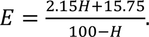
Therefore, the above two Mooney-Rivlin parameters can be calculated by the following equations according to the empirical formulas in the literature (Charlton et al., 1994; Huang and Hsu, 2018; Liu et al., 2022):
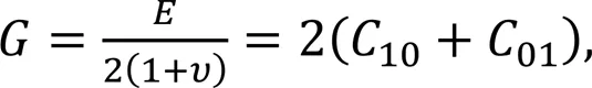

whereis the shear modulus, andis Poisson's ratio, which is assumed equal to 0.499 for such an incompressible rubber material.
Some typical Mooney-Rivlin parameters under different rubber hardnesses are presented in Table 1, so as to quantify the influence of rubber hardness on sealing characteristics in subsequent sections.
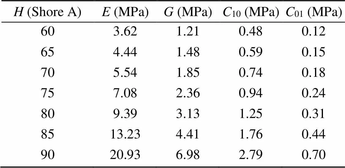
Table 1 Mooney-Rivlin parameters of NBR under different Shore A hardnesses
2.2.2Mixed lubrication model
As the only dynamic friction pair, the primary sealing zone, where the complex thermal-fluid-structure coupling problem occurs, is a key object of lubrication analysis. To accurately determine this region in static contact mechanical analysis, the constitutive model of rubber in Section 2.2.1 is coupled in finite element analysis software ANSYS, and the stretching effect of the rubber material is considered in the establishment of the finite element model (Peng et al., 2021b). Specifically, the PLANE183 element (a higher-order 2D, 8-node element) is employed, and the mesh in the primary sealing zone is locally refined to improve the mesh quality. To ensure numerical accuracy and computational efficiency, 11844 elements are used in the simulation, as the deviation in static contact pressure is less than 0.4% when the element number ranges from 11844 to 76386. The contact pairs between the rubber O-ring and the rod, and the rubber O-ring and the housing are set, with the contact type set to "Surface-to-Surface" and the contact element types set to "CONTACT172" and "TARGE169". To solve the contact problem, the enhanced Lagrange contact algorithm is used.
Thus, the macro profile of the deformed seal, the sealing zone lengthof the primary sealing zone, and the static contact pressurescof the contact zones can be obtained by solving the model within the mechanical boundary conditions shown in Fig. 2. It is confirmed that the seal operates in a mixed lubricating condition as the rod moves, that is, the load in the primary sealing zone is supported partly by the fluid film and partly by surface asperities. To accurately simulate the seal behavior, a mixed lubrication model that focusses on revealing the flow phenomenon of lubricant in the primary sealing zone and includes fluid mechanics analysis, contact mechanics analysis, deformation analysis, and thermal analysis, is developed (Wang et al., 2018b).
In fluid mechanics analysis, it is assumed that the behavior of the lubricant in the sealing gap between deformed seal and moving rod is as a Newtonian laminar fluid. Considering the effects of fluid cavitation and surface roughness, the fluid film pressurefcan be calculated by the following averaged Reynolds equation:
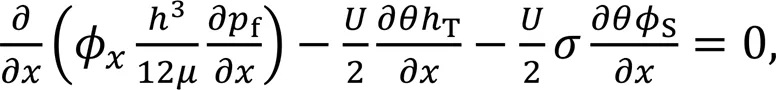
whereis the axial coordinate,is the fluid film thickness,is the rod speed along-direction,Tis the truncated film thickness,is the fluid dynamic viscosity,is the fluid density ratio,is the root mean square (RMS) surface roughness, andϕandSare the flow factors.
Fig. 2 Mechanical boundary conditions of a hydraulic O-ring rod seal. pa is the ambient pressure
The fluid dynamic viscosity of hydraulic oil is affected by fluid pressure and temperature, which can be calculated by the following formula:

where0is the reference viscosity,is the viscosity-pressure coefficient,is the viscosity-temperature coefficient,is the fluid film temperature, and0is the reference temperature.
In contact mechanics analysis, the asperity contact pressureccan be calculated by the following formula derived from the Green-Williamson contact model:
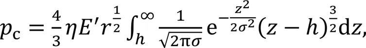
whereis the density of asperities,is the radius of asperities, and΄ is the equivalent elastic modulus.
In deformation analysis, the fluid film thicknessattached to the primary sealing zone can be updated by an influence coefficient method that is based on small deformation theory, as follows:
wherehis the film thickness at theth node,sis the static film thickness,nis the influence coefficient matrix, subscriptsandare theth row andth column of the matrix, andis the total number of nodes.
In thermal analysis, the fluid film temperatureresulting from frictional heat can be calculated by an approximate solution of the classic heat conduction equation, as follows:
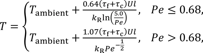
whereambientis the ambient temperature.=RR/Ris the Peclet number.R,R, andRare the density, specific heat, and thermal conductivity of the rod, respectively.is half of the contact width of the primary sealing zone.fandcare the fluid viscous friction stress and the contact shear stress, respectively.
2.3 Boundary conditions and numerical algorithm
The mechanical boundary conditions of a hydraulic O-ring rod seal are illustrated in Fig. 2. The loads caused by fluid pressure and interference fit are applied to the seal surface correspondingly according to the contact principle. That is the application of the sealed pressuresealedon the partial of the surface profile where it is exposed to the hydraulic oil environment and applying the displacement constraint on the partial of the surface profile where it is in contact with the static housing and moving rod. The sealed pressure is imposed by using the fluid pressure penetration command stream. In the primary sealing zone, to solve Eq. (5), the force boundary conditions (f=sealed,f=a) are applied with an assumption of fully flooded lubrication.
Since this analysis is a complicated muti-field coupling problem and the solution of fluid film pressure in Eq. (5) is implicit, the iterative approach shown in Fig. 3 is adopted. In order to ensure rapid convergence and good numerical stability for such a complex nonlinear problem, the finite element method coupled relaxation iterative algorithm with convergence criterion 10-7is employed (Wang et al., 2019). When the whole computation is converged, the auxiliary results such as flow rate, friction forceR, net leakage, and frictional power lossare determined to evaluate the sealing performance by the following formulations:
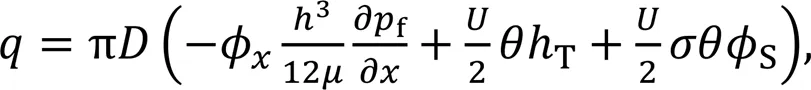
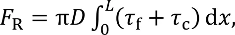
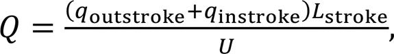

whereis the rod diameter.
Fig. 3 Flowchart of the computational procedure
3 Analysis and discussion of results
The structural parameters of seal and rod, the physical parameters of lubricant, and the operating conditions that are used in the following numerical simulation are listed in Table 2.
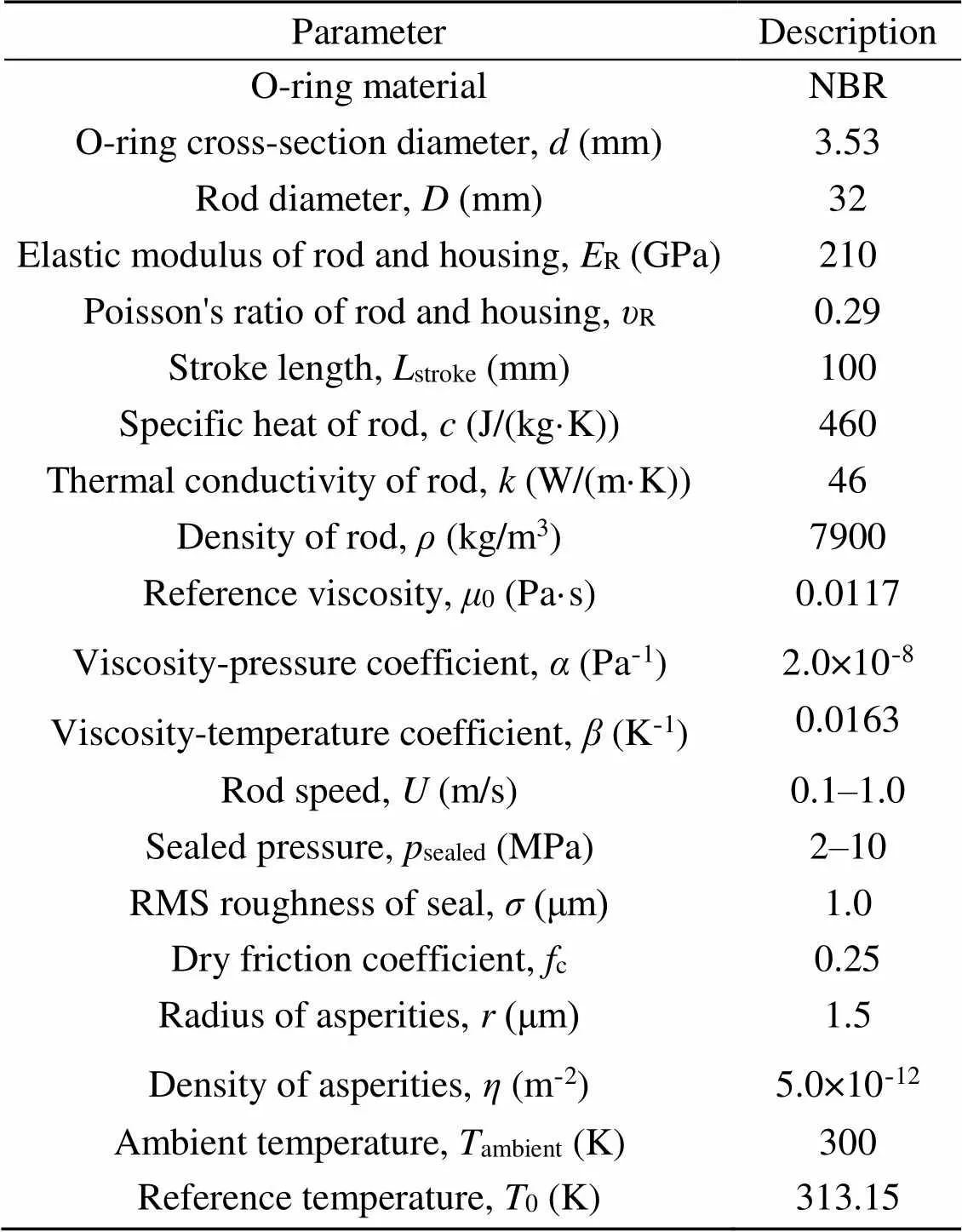
Table 2 Computational parameters
3.1 Effect of rubber hardness on static mechanical properties
To investigate the effect of rubber hardness on the static mechanical properties of the hydraulic O-ring rod seal, the von Mises stress distribution, the static contact pressure, and the contact width are presented. According to the von Mises stress distribution, the stress concentrated position, which normally is also the potential failure position of the seal, can be predicted, so as to help us to avoid seal failure, if possible, by the product design in advance. The maximum static contact pressure is widely used in engineering applications for initially judging whether the seal meets with the requirements of static sealing characteristics; it is considered that it should be not less than the sealed pressure. In addition, the contact width characterizes the leaking distance of fluid for the seal, with a consensus that a greater value is favorable for preventing leakage but is unfavorable for reducing friction (Lin et al., 2022).
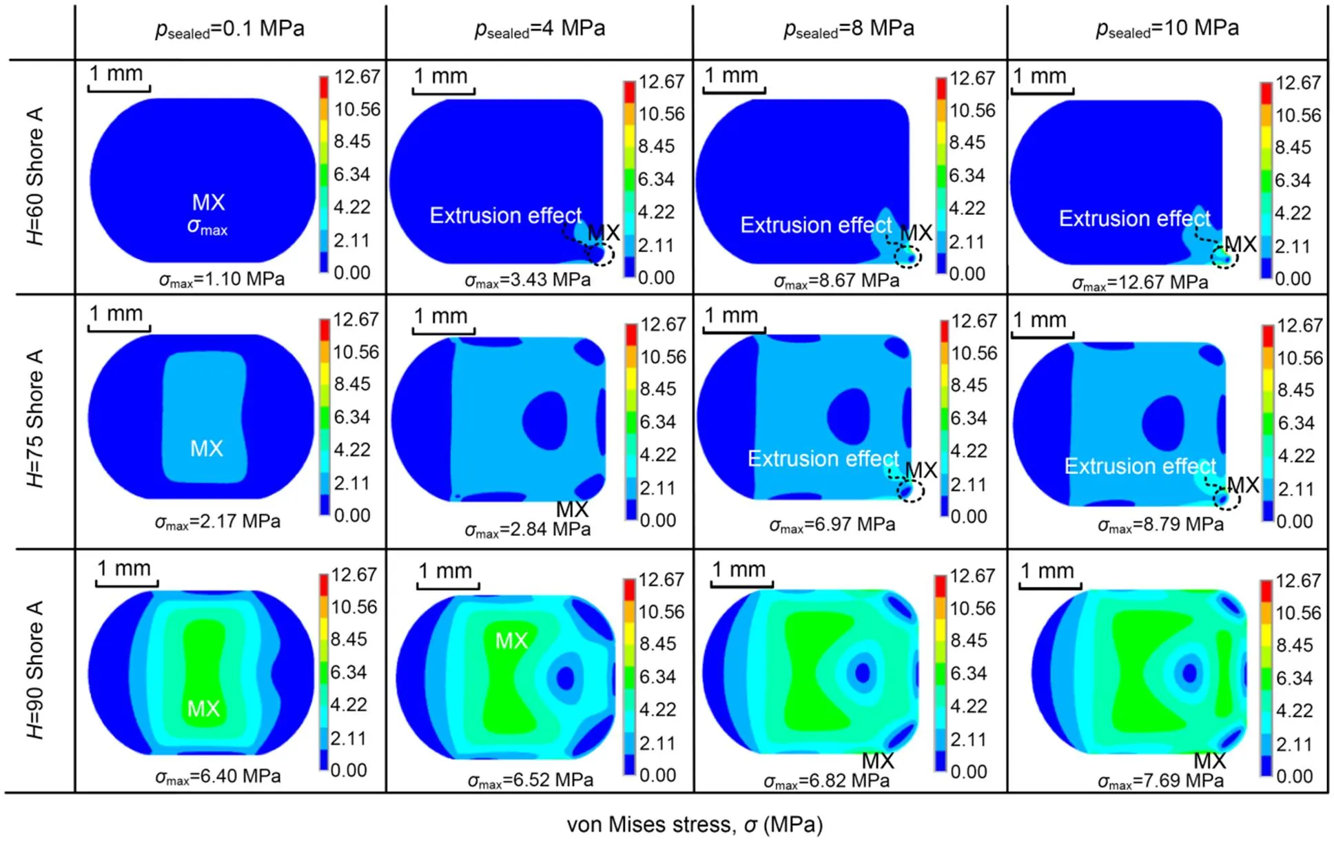
Fig. 4 von Mises stress distributions under different rubber hardnesses. MX indicates the location of the maximum value
The von Mises stress distributions of several typical rubber hardnesses under different sealed pressures are shown in Fig. 4. When the seal is operated at 4 MPa with a 60 Shore A hardness, the partial of the seal near the air side is extruded into the narrow gap between rod and housing, and so induces the extrusion effect. With the increase in sealed pressure, the extrusion effect becomes more obvious, and results in larger values of extrusion volume, extrusion distance, and von Mises stress. According to Nikas (2003) and Zhang et al. (2020), the obvious extrusion effect will lead to a greater local concentrated stress or even gap-bite in dynamic conditions, and finally to seal failure. With the increase in rubber hardness, the extrusion effect becomes weakened or even disappears when the rubber hardness is increased to 90 Shore A. This is because a high hardness rubber usually has a higher acrylonitrile content and a stronger dipolar interaction between polymer chains, which limits the mobility of the polymer chains and strengthens the anti-extrusion characteristics (Lee and Ha, 2021). As shown in Fig. 4, the position where the stress concentration phenomenon happens, is changed from the inner region to the surface contacting with the rod and then to the extruded region of the seal ring, with the increase of sealed pressure or the decrease of rubber hardness. It can be also found that the seal with a higher rubber hardness has a stronger anti-deformation especially under high sealed pressures but it is followed by a more non-uniform stress distribution.
Usually, the region where the stress concentration occurs is determined by the maximum von Mises stress. Fig. 5 presents the maximum von Mises stress under different rubber hardnesses and sealed pressures. As shown in Fig. 5a, the value of the maximum von Mises stress is a minimum in the range of simulated parameters when the seal has a hardness of 60 Shore A and under a pressure of 0.1 MPa. Its maximum value (about 13 MPa) occurs in the conditions of 60 Shore A and 10 MPa, and is much larger than that in the conditions of 90 Shore A and 10 MPa due to the significant extrusion effect as shown in Fig. 4. It means that the extrusion effect exacerbates the stress concentration behavior, or even induces rubber tear damage, when the allowable stress is greatly exceeded, and thus a failed seal is created especially in dynamic conditions (Zhang et al., 2020). Normally, the stress should be increased with the increase of rubber hardness without consideration of the extrusion effect. To quantitatively evaluate the extrusion effect on stress, Fig. 5b presents the relationships between the maximum von Mises stress and the rubber hardness under different sealed pressures. It can be found that the maximum von Mises stress is increased with the increase of rubber hardness when the sealed pressure is not larger than 2 MPa, while it decreases firstly followed by an increase when the sealed pressure is further increased. This is because the extrusion effect of the seal, which promotes high stress, occurs much more easily when the rubber hardness is low, but as the rubber hardness increases, it is weakened until it disappears. For high pressure cases, when the extrusion effect exactly disappears, the maximum von Mises stress in that rubber hardness is the minimum and occurs on the surface of the seal ring that contacts with the rod near the air side. In addition, with the increase of sealed pressure, the minimum hardness corresponding to the key points (1)–(5) where the extrusion effect disappears becomes larger.
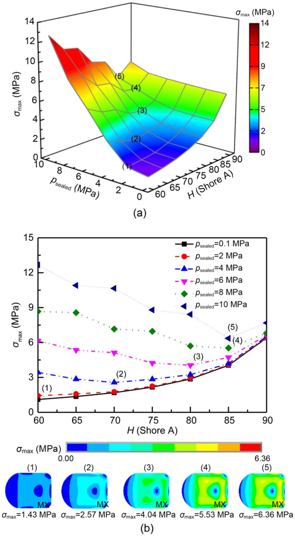
Fig. 5 Effect of rubber hardness on the maximum von Mises stress: (a) maximum von Mises stress distributions under different rubber hardnesses and sealed pressures; (b) maximum von Mises stress versus rubber hardness under different sealed pressures
The static contact pressure distributions of several typical rubber hardnesses under different sealed pressures are shown in Fig. 6. It can be seen that the contact widths of the primary and secondary sealing zones increase with the increase of sealed pressure, but they decrease with the increase of rubber hardness due to its strong deformation-resistant capacity especially under high-sealed-pressure conditions. The static contact pressures also increase significantly as the sealing pressure and rubber hardness increase, especially in the region where the seal is in contact with the rod and the housing bottom. It means that the sealing function of such a radial seal is enhanced, since the fluid is prevented, mainly by the radial force, from reducing the leakage gap. In addition, both the maximum static contact pressures of the primary and secondary sealing zones are larger than that of the sealed pressure, which indicates that the static sealing characteristic is satisfied. However, there is little extrusion effect on static contact pressure and contact width.
To further evaluate the rubber hardness on the static sealing characteristic, the maximum static contact pressure and the sealing zone length of the primary sealing zone are shown in Figs. 7 and 8, respectively. It can be found that the maximum static contact pressure increases linearly with the increase of sealed pressure and increases slowly first and then sharply with the increase in rubber hardness. The sealing zone length decreases with the increase of rubber hardness, especially in high-sealed-pressure cases. However, the radial force between rod and seal is increased with the increase in rubber hardness, which can be calculated by integrating the static contact pressure in the sealing zone. All these results indicate that the seal with a high rubber hardness has a better performance in the analysis of the static mechanical properties. However, it should be noted that the harder rubber has some potential disadvantages, especially under thermal oxidation/oil aging conditions. According to Jiang et al. (2019) and Li et al. (2021), the NBR becomes hard and brittle, loses elasticity, decreases tensile and tear strength, and even shows cracks with increases in aging temperature and time.
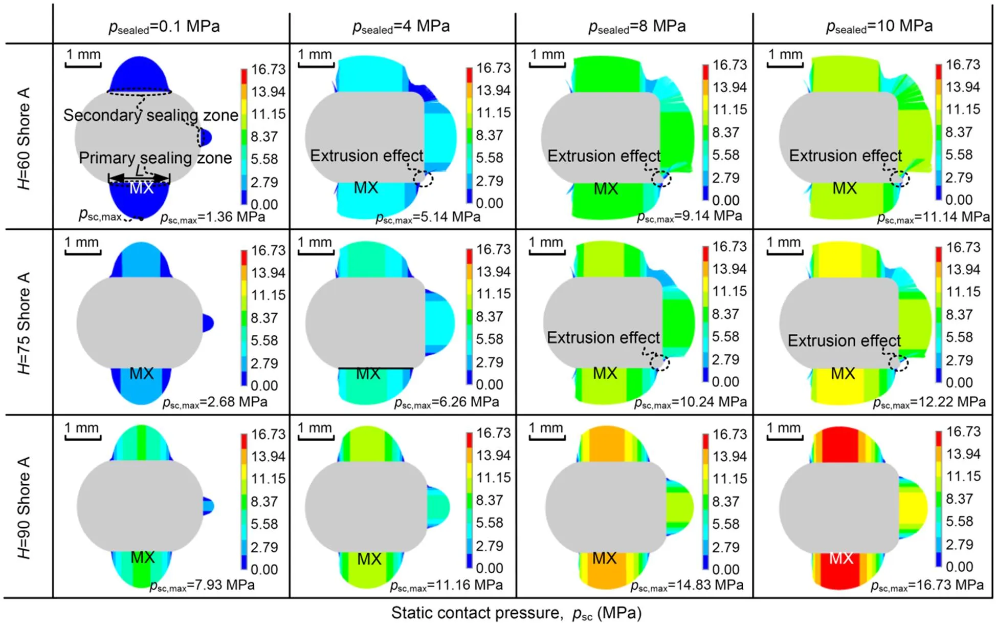
Fig. 6 Static contact pressure distributions under different rubber hardnesses
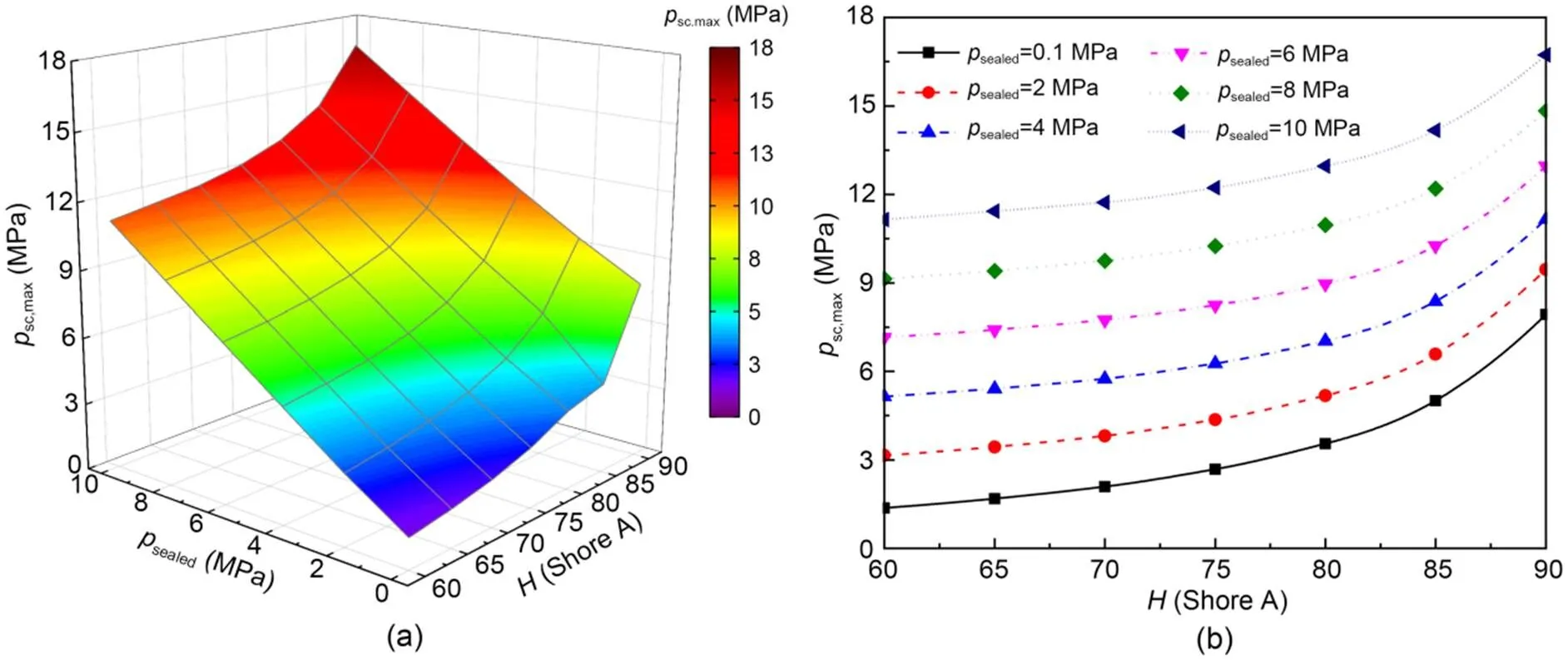
Fig. 7 Effect of rubber hardness on the maximum static contact pressure: (a) maximum static contact pressure under different rubber hardnesses and sealed pressures; (b) maximum static contact pressure versus rubber hardness under different sealed pressures
3.2 Effect of rubber hardness on dynamic sealing performances
To further investigate the effect of rubber hardness on the dynamic behavior of the seal and its performance, the minimum film thickness, the flow rate, and the friction force, which can characterize the lubrication conditions and evaluate the sealing performance, are calculated and analyzed in this section.
Fig. 9 presents the rubber hardness effect on the minimum film thickness during outstroke and instroke. During outstroke, as shown in Figs. 9a and 9b, the minimum film thickness decreases with the increase in rubber hardness under all rod speed conditions, although a larger rod speed can increase the film thickness. Since the hydrodynamic pressure caused by the rod speed is far less than the contact pressure, the rod speed effect on film thickness is almost negligible compared to the rubber hardness effect, which, as mentioned before, makes a great contribution to the static contact pressure. During instroke, with the increasing of sealed pressure and the reversing rod speed as shown in Figs. 9c and 9d, the minimum film thickness gradually decreases as the hardness increases and is less than that during outstroke under the same rod speed conditions. Compared to the outstroke, the effect of rod speed on minimum film thickness is further weakened because the hydrodynamic pressure generated is the result of resisting the reverse hydrostatic pressure. Although there is still a little interaction effect of rubber hardness and rod speed on film thickness, the rubber hardness shows a large interaction effect on it with the sealed pressure. In addition, the effect of sealed pressure on minimum film thickness, to decrease it by improving the seal deformation, is also gradually weakened with increase in rubber hardness. It can also be demonstrated that the seal is under mixed lubrication since the ratio of film thickness to roughness is less than 3 under the simulation conditions.
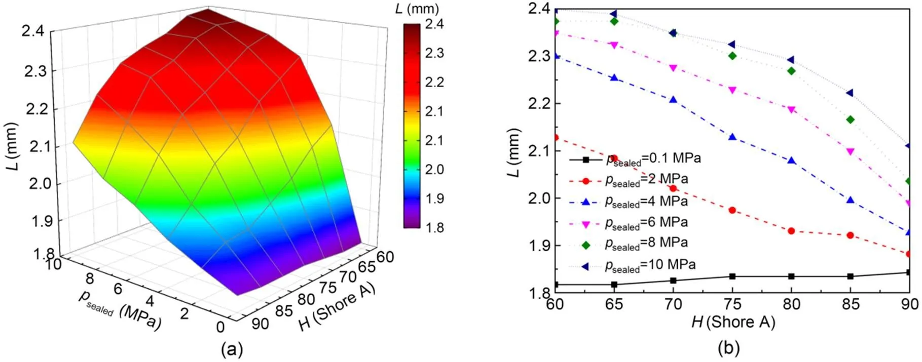
Fig. 8 Effect of rubber hardness on the sealing zone length: (a) sealing zone length distributions under different rubber hardnesses and sealed pressures; (b) sealing zone length versus rubber hardness under different sealed pressures
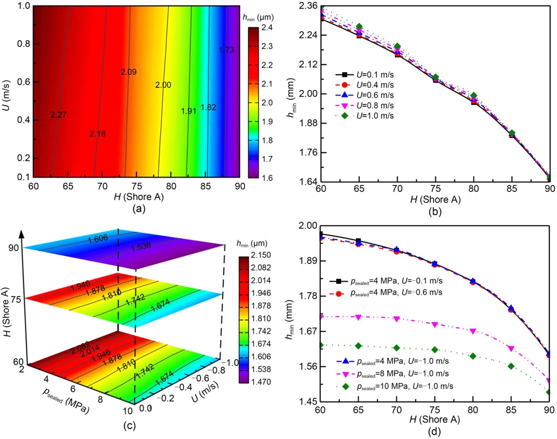
Fig. 9 Effect of rubber hardness on the minimum film thickness: (a) minimum film thickness distributions under different rubber hardnesses and rod speeds during outstroke; (b) minimum film thickness versus rubber hardness under different rod speeds during outstroke; (c) minimum film thickness distributions with three types of rubber hardnesses under different rod speeds and sealed pressures during instroke; (d) minimum film thickness versus rubber hardness under different rod speeds and sealed pressures during instroke
Fig. 10 presents the rubber hardness effect on the flow rate during outstroke and instroke. It can be seen that the flow rate during outstroke is always positive but is negative during instroke, which is the so-called leakage rate, which characterizes the fluid leaks; the pumping rate characterizes the leaked fluid pumps back into the hydraulic cylinder again. During outstroke, as shown in Figs. 10a and 10b, the leakage rate is slightly decreased with the increase in rubber hardness, and the rubber hardness effect on it shows a certain degree of enhancement as the rod speed increases. A similar phenomenon can be found in the rubber hardness effect on the pumping rate during instroke, and this effect is applicable when the pumping rate decreases due to the increase of sealed pressure, as shown in Figs. 10c and 10d. This is because a high rubber hardness will reduce the film thickness, as mentioned before, and thus the fluid resistances to leak and pump are all increased. However, the absolute value of the leakage rate during outstroke is always larger than that of the pumping rate during instroke at every rod speed or sealed pressure, indicating that the seal is in leak state in the simulated conditions.
Fig. 11 presents the rubber hardness effect on the friction force during outstroke and instroke. It can be seen that the friction force is increased with the increase of rubber hardness during both outstroke and instroke, which is mainly due to the contribution of rubber hardness to the contact shear stress causing by contact pressure. During outstroke, the friction force in 90 Shore A hardness is more than 8 times that in 60 Shore A hardness, but it is hardly influenced by the rod speed in the simulation conditions. During instroke, although the friction force tends to increase with the increasing of sealed pressure and rod speed, it seems that the effects of both sealed pressure and rod speed on the friction force are weakened as the rubber hardness increases. In addition, its friction force is much larger than that during outstroke under the same rod speed conditions due to the increased sealed pressure, especially when the rubber hardness is low. This is due to the fact that the ability of such a seal to resist deformation increases with the increase of rubber hardness under the comprehensive effect of the increased contact pressure and the decreased contact width and thus slows down the increasing trend of contact shear stress that plays a dominant role in friction.

Fig. 10 Effect of rubber hardness on the flow rate: (a) flow rate distributions under different rubber hardnesses and rod speeds during outstroke; (b) flow rate versus rubber hardness under different rod speeds during outstroke; (c) flow rate distributions with three types of rubber hardnesses under different rod speeds and sealed pressures during instroke; (d) flow rate versus rubber hardness under different rod speeds and sealed pressures during instroke
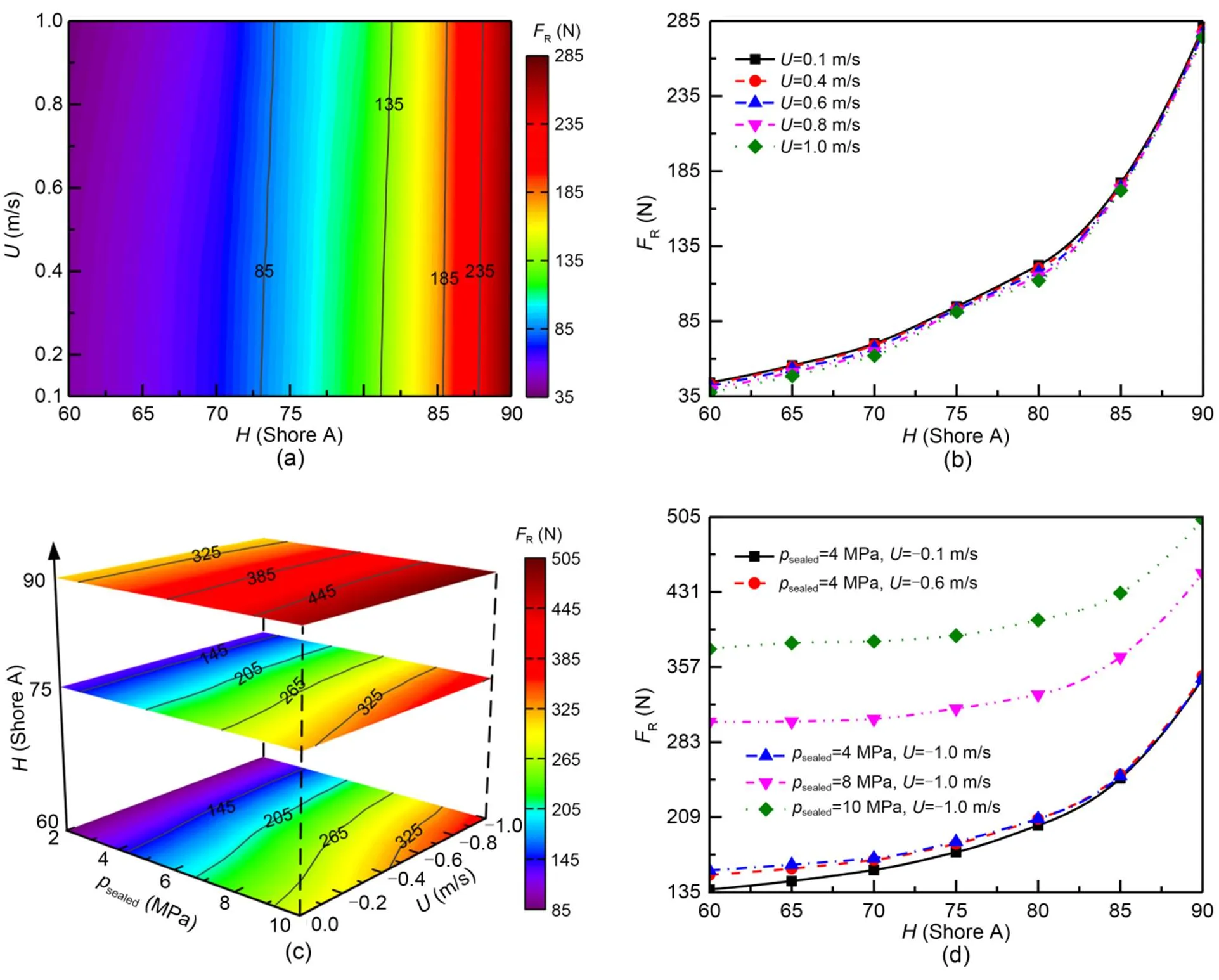
Fig. 11 Effect of rubber hardness on the friction force: (a) friction force distributions under different rubber hardnesses and rod speeds during outstroke; (b) friction force versus rubber hardness under different rod speeds during outstroke; (c) friction force distributions with three types of rubber hardnesses under different rod speeds and sealed pressures during instroke; (d) friction force versus rubber hardness under different rod speeds and sealed pressures during instroke
The above results indicate that the seal with a high rubber hardness seems to show a strong performance in preventing leakage but a weak performance in reducing friction, which is achieved by reducing the film thickness and can be regarded as an enhancement of the static sealing function.
3.3 Optimized selection of rubber hardness
In Sections 3.1 and 3.2, the rubber hardness effects on the static mechanical properties and the dynamic sealing performances are analyzed and discussed, and show significant but complex impacts. In this section, the rubber hardness is optimized in static and dynamic sealing applications.
3.3.1Optimization objectives and procedures
For a seal operating at the hydrostatic conditions, it is believed that there should be no leakage and as little material damage as possible. According to previous research, the maximum static contact pressure and the maximum von Mises stress are the two key parameters for evaluating the static sealing characteristics (Zhang et al., 2016). The optimization procedure of rubber hardness can be summarized as follows:
Step 1: Obtain the optimized zone I, in which the maximum static contact pressure is not less than the hydrostatic pressure.
Step 2: Obtain the re-optimized zone II within zone I, in which the maximum von Mises stress is not more than the allowable stress of the rubber material.
Step 3: Determine the optimum value, in which the maximum von Mises stress is the minimum within zone II.
For a seal operating at the dynamic conditions, it is believed that there should be as low leakage and low friction as possible. The net leakage and the frictional power loss are applied to evaluate the dynamic sealing characteristics in the perspective of one cycle (Wang et al., 2018a). The optimization procedure of rubber hardness can be summarized as follows:
Step 1: Set up the allowable net leakage, according to the technical specification or engineering requirement.
Step 2: Obtain the optimized zone III, in which the net leakage is not more than the allowable net leakage.
Step 3: Determine the optimum value, in which the frictional power loss is the minimum within zone III.
In addition, if a seal is serving as both static seal and dynamic seal within a life cycle, the optimum rubber hardness should be determined at the intersection of zones II and III.
3.3.2Case studies
It should be noted that the allowable stress of NBR material is 15 MPa in this study (Zhang et al., 2020). That means that the rubber hardness of the O-ring seal always meets the requirements of the hydrostatic applications shown in the above Steps 1 and 2 in the simulated conditions according to the results in Section 3.1. Therefore, for a static seal, the optimum rubber hardness under different hydrostatic pressures can be concluded from the analysis results presented in Section 3.1. For example, in the case of 2 MPa, the optimized zone I of rubber hardness is 60–90 Shore A since their maximum static contact pressures are all greater than 2 MPa according to the results shown in Fig. 7, the re-optimized zone II of rubber hardness is also 60–90 Shore A due to the fact that their maximum von Mises stresses are all not more than 15 MPa according to the results shown in Fig. 5, and, finally, the optimum value of rubber hardness is 60 Shore A as shown in Fig. 5b. By introducing a deviation of 5 Shore A on the optimum rubber hardness, the optimized range of rubber hardness under different static conditions can be obtained as shown in Table 3.
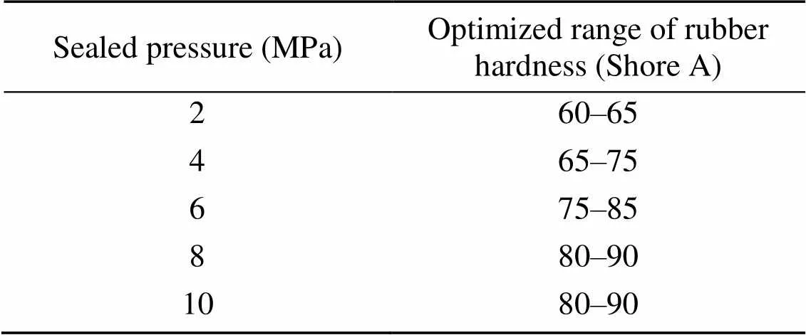
Table 3 Optimized range of rubber hardness under different static conditions
For a dynamic seal, the allowable net leakage, for example 1 drop per 10 cycles, is determined according to the standard AMM TASK 29-00-00-790-001 in an aircraft maintenance manual (Airbus, 2012). Besides, two more stringent criteria of the allowable net leakage, such as 1 drop per 20 cycles or even per 40 cycles, are adopted in this section to adapt to applications with higher sealing requirements in engineering practice. For the lubricant of 15# hydraulic oil, it is assumed that the total volume of 20 drops is about 1 mL, and thus the three allowable net leakages can be converted to 0.005 mL/cycle (allowable net leakage I), 0.0025 mL/cycle (allowable net leakage II), and 0.00125 mL/cycle (allowable net leakage III). In addition, the other input parameters are consistent with those in Section 3.2 above, as can be seen in Table 1.
Fig. 12 presents the optimized rubber hardness of allowable net leakage under different operating conditions. According to the results under different conditions (sealed pressure, rod speed, and rubber hardness) shown in Fig. 12a, the fitting surfaces of the allowable net leakages I, II, and III, in which the net leakages are just equal to the values of each standard, are determined. All the net leakages on the outside of each fitting surface exceed the corresponding maximum allowed, while only some of the conditions on the inside are less than it. From the outside to the inside, namely decreasing the sealed pressure but increasing the rod speed, the three fitting surfaces correspond to the allowable net leakages I, II, and III, respectively. The optimized zones of rubber hardness within the allowable net leakages I and II, labeled yellow and blue, are shown in Figs. 12b and 12c, respectively. Most of the simulated conditions in Fig. 12b meet the requirement except for some of the conditions of low rod speed but high sealed pressure, even with a high rubber hardness. The optimized zone is significantly reduced when less leakage is allowed, and the low hardness rubber is only happened on the conditions of low sealed pressure and high rod speed, as shown in Fig. 12c. According to the net leakage of five specific conditions under three allowable indices shown in Fig. 12d, the optimized values of rubber hardness can be obtained where its net leakage is less than that of the corresponding allowable net leakage. For example, in the case of 4 MPa and 0.1 m/s, the optimized rubber hardness should be larger than 81.4 Shore A.
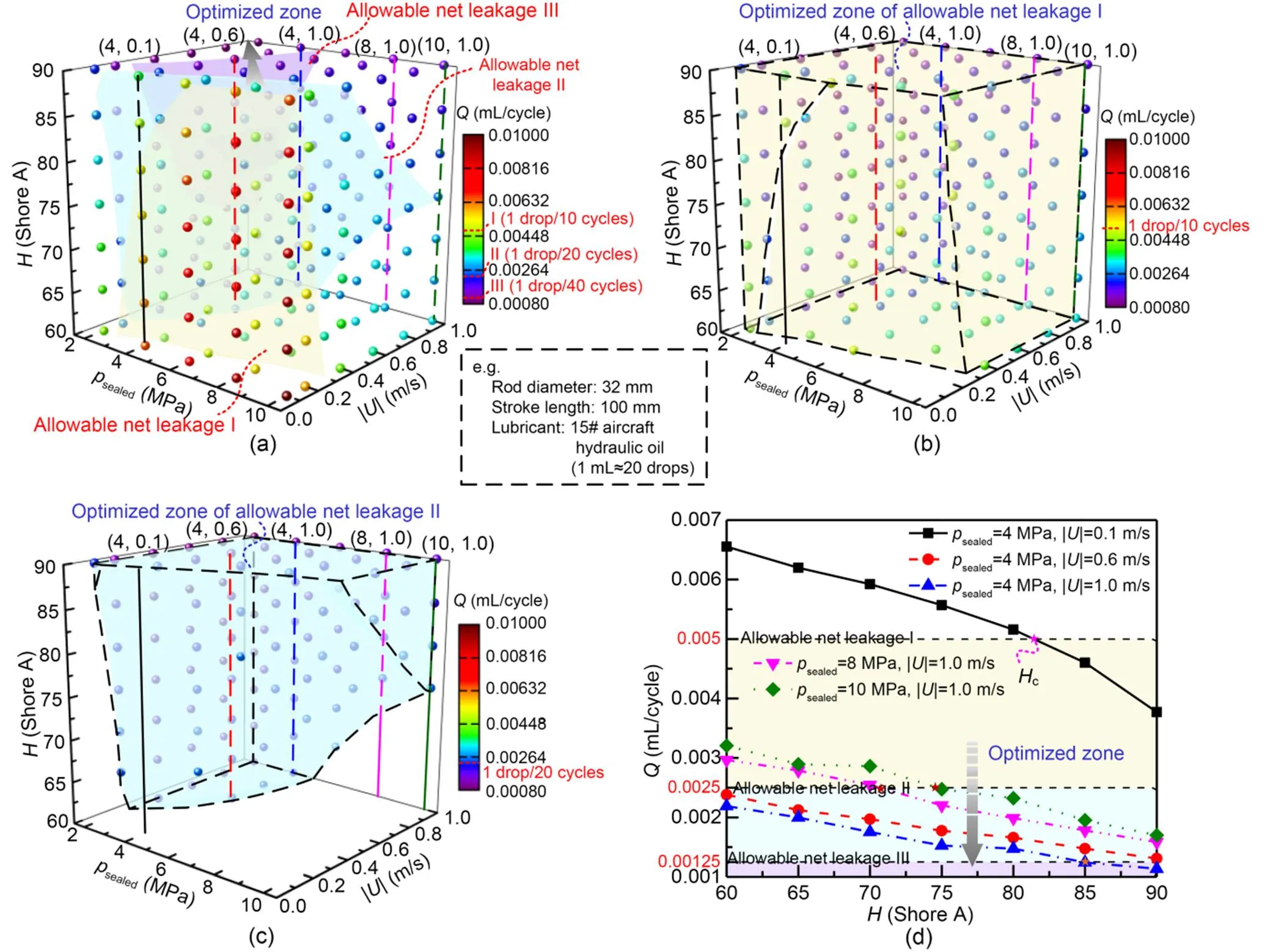
Fig. 12 Optimized rubber hardness of allowable net leakage under different operating conditions: (a) fitting surfaces of three allowable indices; (b) optimized zone of allowable net leakage I; (c) optimized zone of allowable net leakage II; (d) optimum rubber hardness of three allowable indices. Hc is the optimum rubber hardness. References to color refer to the online version of this figure
Fig. 13 presents the optimized rubber hardness of minimum friction power loss under different operating conditions. Similarly, the three fitting surfaces where the net leakages of these conditions meet with the corresponding allowable net leakages I, II, and III are shown in Fig. 13a, to make the optimization easier to understand. It can be found that the frictional power loss of a high-hardness seal operating at high sealed pressure and rod speed is the maximum, while that of a low-hardness seal operating at low sealed pressure and rod speed is the minimum. As shown in Fig. 13b, the frictional power losses are all increased with the rubber hardness under all conditions. That means the optimum rubber hardnesscis the minimum value meeting the leakage standard; for example, it is 81.4 Shore A in the case of 4 MPa and 0.1 m/s.
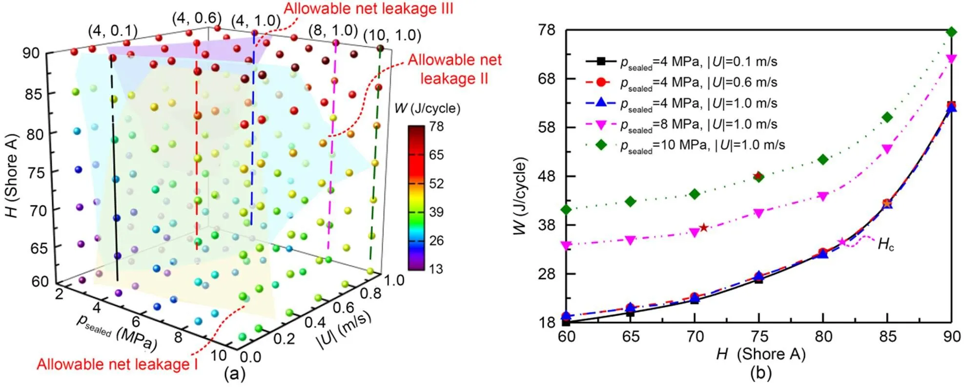
Fig. 13 Optimized rubber hardness of minimum frictional power loss under different operating conditions: (a) fitting surfaces of three allowable indices; (b) optimum rubber hardness of three allowable indices
According to the above results, under both hydrostatic and dynamic conditions, the optimum rubber hardnesses under different operating conditions and leakage criteria can be concluded as shown in Table 4. Therefore, the table can help us to directly select the optimum rubber hardnesses applicable to different operating conditions.
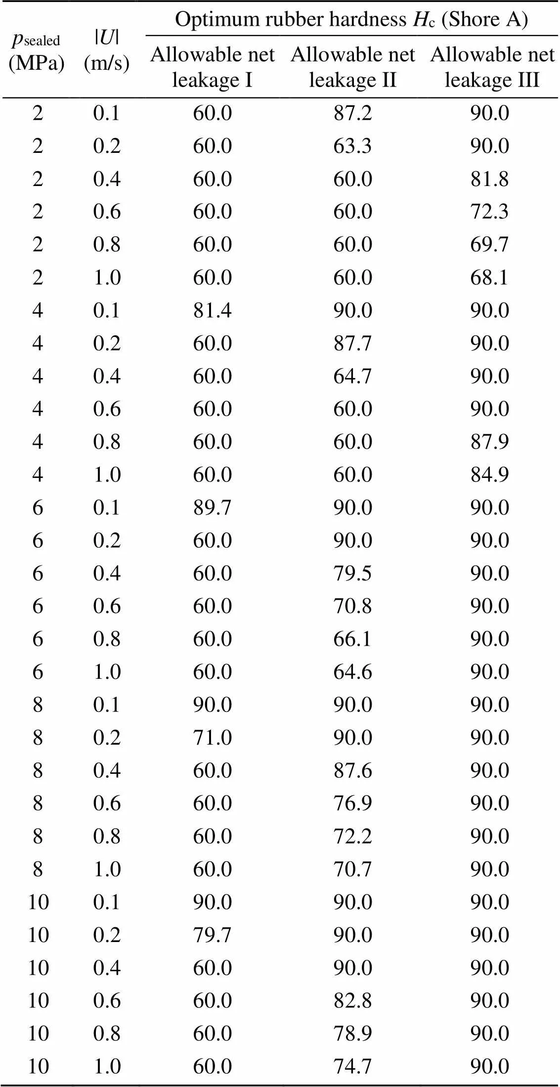
Table 4 Optimum rubber hardness under different operating conditions and leakage criteria
Furthermore, a multi-component regression is also conducted to quantitatively evaluate which factors contribute the most to minimize leakage and friction. The net leakageand frictional power losscan be expressed as a function of rubber hardness, sealed pressuresealed, and rod speed || in the form of Eqs. (14) and (15), respectively. In addition, || has the most significant effect onfollowed bysealedand, whilehas the most significant effect onfollowed bysealedand ||, according to the standardized coefficients in the regression analysis.


4 Conclusions
In this paper, the effects of NBR hardness on the sealing characteristics of hydraulic O-ring rod seals applied in static and dynamic conditions are numerically analyzed by using a mixed lubrication elastohydrodynamic model. The influence mechanism of rubber hardness on seal behavior is revealed, and the influence law of rubber hardness on sealing performance is evaluated quantitatively. Furthermore, the optimized selection of rubber hardnesses under some operating conditions is proposed to maximize the sealing performance. The results are summarized as follows:
(1) With the increase of rubber hardness, the resistance to deformation of the O-ring seal is enhanced, and then the static contact pressure is increased and the minimum film thickness is decreased, which is conducive to preventing leakage, but not conducive to reducing friction.
(2) The low-rubber-hardness seal is prone to the extrusion effect and induced stress concentration especially under high-sealed-pressure conditions and is recommend for use at high speed or on other occasions with low sealing requirements.
(3) The high-rubber-hardness seal has better dynamic and static sealing performances but with a high friction force. It is especially recommended for application under high-pressure conditions. As far as possible, and under the premise of not exceeding the leakage requirements, low rubber hardness should be selected so as to reduce friction.
This work is supported by the National Natural Science Foundation of China (No. 52005470), the Natural Science Foundation of Zhejiang Province (No. LQ21E050020), and the Fundamental Research Funds for the Provincial Universities of Zhejiang (No. 2021YW17), China.
Xiaoxuan LI and Bingqing WANG designed the research. Xiaoxuan LI processed the corresponding data and wrote the first draft of the manuscript. Bingqing WANG, Xudong PENG, Yuntang LI, Xiaolu LI, Yuan CHEN, and Jie JIN helped to organize the manuscript. Xiaoxuan LI and Bingqing WANG revised and edited the final version.
Xiaoxuan LI, Bingqing WANG, Xudong PENG, Yuntang LI, Xiaolu LI, Yuan CHEN, and Jie JIN declare that they have no conflict of interest.
Airbus, 2012. A318/A319/A320/A321 Aircraft Maintenance Manual, Check of the External Leaks of the Hydraulic Components, AMM TASK 29-00-00-790-001. Airbus, Toulouse, France.
Charlton DJ, Yang J, Teh KK, 1994. A review of methods to characterize rubber elastic behavior for use in finite element analysis., 67(3):481-503. https://doi.org/10.5254/1.3538686
Cheng GL, Guo F, Zang XH, et al., 2022. Failure analysis and improvement measures of airplane actuator seals., 133:105949. https://doi.org/10.1016/j.engfailanal.2021.105949
Elhard JD, Duguid A, Heinrichs M, 2017. Research on Safety Technology Verification for Materials and Corrosions in the US Outer Continental Shelf (OCS), High Pressure High Temperature (HPHT) Material Evaluation. Technical Assessment Program Report (TAP 767AA), Bureau of Safety and Environmental Enforcement, Battelle, USA.
Feyzullahoğlu E, 2015. Abrasive wear, thermal and viscoelastic behaviors of rubber seal materials used in different working conditions., 229(1):64-73. https://doi.org/10.1177/1350650114541750
GAQSIQ (General Administration of Quality Supervision, Inspection and Quarantine of the People’s Republic of China), 2005. Housing Dimensions for O-ring Elastomer Seals in Hydraulic and Pneumatic Applications, GB/T 3452.3–2005. National Standards of the People’s Republic of China (in Chinese).
Gent AN, 1958. On the relation between indentations hardness and Young’s modulus., 31(4):896-906. https://doi.org/10.5254/1.3542351
Gent AN, 2012. Engineering with Rubber: How to Design Rubber Components. 3rd Edition. Carl Hanser Verlag, Munich, Germany, p.37-41.
Han CJ, Zhang H, Zhang J, 2015. Structural design and sealing performance analysis of biomimetic sealing ring., 2015:358417. https://doi.org/10.1155/2015/358417
Huang YC, Hsu HC, 2018. Numerical simulation and experimental validation of novel hyperelastic micro-motion manipulator for water conserving device., 24(8):3329-3339. https://doi.org/10.1007/s00542-017-3680-6
Jiang BQ, Jia XH, Wang ZX, et al., 2019. Influence of thermal aging in oil on the friction and wear properties of nitrile butadiene rubber., 67(3):86. https://doi.org/10.1007/s11249-019-1201-8
Lee YS, Ha KR, 2021. Effects of acrylonitrile content on thermal characteristics and thermal aging properties of carbon black-filled NBR composite., 53(5):402-416. https://doi.org/10.1177/0095244320941243
Lee YS, Park SH, Lee JC, et al., 2016. Influence of microstructure in nitrile polymer on curing characteristics and mechanical properties of carbon black-filled rubber composite for seal applications., 48(8):659-676. https://doi.org/10.1177/0095244315613621
Li B, Li SX, Shen MX, et al., 2021. Tribological behaviour of acrylonitrile-butadiene rubber under thermal oxidation ageing., 93:106954. https://doi.org/10.1016/j.polymertesting.2020.106954
Liang BL, Yang X, Wang ZL, et al., 2019. Influence of randomness in rubber materials parameters on the reliability of rubber O-ring seal., 12(9):1566. https://doi.org/10.3390/ma12091566
Lin ZH, Yu LJ, Hua TF, et al., 2022. Seal contact performance analysis of soft seals on high-pressure hydrogen charge valves., 23(4):247-256. https://doi.org/10.1631/jzus.A2100395
Liu D, Yun FH, Jiao KF, et al., 2022. Structural analysis and experimental study on the spherical seal of a subsea connector based on a non-standard O-ring seal., 10(3):404. https://doi.org/10.3390/jmse10030404
Mooney M, 1940. A theory of large elastic deformation., 11(9):582-592. https://doi.org/10.1063/1.1712836
Nikas GK, 2003. Analytical study of the extrusion of rectangular elastomeric seals for linear hydraulic actuators., 217(5):365-373. https://doi.org/10.1243/135065003322445287
Nikas GK, 2018. Parametric and optimization study of rectangular-rounded, hydraulic, elastomeric, reciprocating seals at temperatures between -54 and +135 ℃., 6(3):77. https://doi.org/10.3390/lubricants6030077
Peng C, Ouyang XP, Schmitz K, et al., 2021a. Investigation of the tribological performance of reciprocating seals in a wide temperature range., 235(11):2396-2414. https://doi.org/10.1177/13506501211004786
Peng C, Ouyang XP, Schmitz K, et al., 2021b. Numerical and experimental study on combined seals with the consideration of stretching effects., 143(6):062301. https://doi.org/10.1115/1.4048496
Scheller J, Baur PJ, 2021. Characterization of leakage, clamping force and retaining force of reusable sealing frame with elastomer O-ring for thin plasma polymeric coated thermoplastic polyester-ether films., 192:110501. https://doi.org/10.1016/j.vacuum.2021.110501
Sukumar T, Bapu BRR, Prasad BD, 2019. Determination of sealing pressure in hyperelastic O-ring with different hardness using numerical method., 51(7-8):684-697. https://doi.org/10.1177/0095244318817889
Ucar H, Basdogan I, 2018. Dynamic characterization and modeling of rubber shock absorbers: a comprehensive case study., 37(3):509-518. https://doi.org/10.1177/1461348417725954
Wang BQ, Peng XD, Meng XK, 2018a. Elastohydrodynamic lubrication characteristics of an O-ring hydraulic rod seal during transient operation. CSAA/IET International Conference on Aircraft Utility Systems, p.348-353. https://doi.org/10.1049/cp.2018.0093
Wang BQ, Peng XD, Meng XK, 2018b. Simulation of the effects of non-Newtonian fluid on the behavior of a step hydraulic rod seal based on a power law fluid model., 19(11):824-842. https://doi.org/10.1631/jzus.A1800096
Wang BQ, Peng XD, Meng XK, 2019. A thermo-elastohydrodynamic lubrication model for hydraulic rod O-ring seals under mixed lubrication conditions., 129:442-458. https://doi.org/10.1016/j.triboint.2018.08.044
Windslow RJ, Busfield JJC, 2019. Viscoelastic modeling of extrusion damage in elastomer seals., 17(3):228-240. https://doi.org/10.1080/1539445X.2019.1575238
Zhang J, Xie JX, 2018. Investigation of static and dynamic seal performances of a rubber O-ring., 140(4):042202. https://doi.org/10.1115/1.4038959
Zhang YW, Shi J, Wang SP, et al., 2016. Sealing mechanism and failure analysis of actuator reciprocating seal. IEEE 11th Conference on Industrial Electronics and Applications, p.2190-2195. https://doi.org/10.1109/ICIEA.2016.7603952
Zhang ZB, Wu DF, Pang H, et al., 2020. Extrusion-occlusion dynamic failure analysis of O-ring based on floating bush of water hydraulic pump., 109:104358. https://doi.org/10.1016/j.engfailanal.2019.104358
题目:丁腈橡胶硬度对O形液压杆封密封性能的影响
作者:李晓暄1,王冰清1,2,彭旭东3,李运堂2,李孝禄2,陈源2,金杰2
机构:1中国计量大学,质量与安全工程学院,中国杭州,310018;2中国计量大学,机电工程学院,中国杭州,310018;3浙江工业大学,机械工程学院,中国杭州,310023
目的:研究丁腈橡胶硬度对O形液压杆封静/动态密封性能的影响,为其工程中橡胶硬度的选型提供理论参考。
创新点:1. 基于混合弹流润滑模型,分析了丁腈橡胶硬度对O形液压杆封静/动态密封性能的影响;2. 以低泄漏、低摩擦为目标,获得了静/动态应用下丁腈橡胶O形液压杆封的橡胶硬度优选范围。
方法:1. 通过数值分析静接触压力、von Mises应力、最小液膜厚度、泄漏率和摩擦力,揭示丁腈橡胶硬度对O形液压杆封静/动态密封性能的影响机理;2. 以最大静接触压力和最大von Mises应力作为静密封性能评价指标,以及以净泄漏量和摩擦功耗作为动密封性能的评价指标,确定丁腈橡胶O形液压杆封的最佳橡胶硬度值。
结论:1. 随着橡胶硬度的增加,丁腈橡胶O形液压杆封的抗变形能力增强,静接触压力增大,最小液膜厚度减小,泄漏量减小,摩擦力增大;2. 低硬度密封易产生挤出效应和应力集中现象,因此更适合在高速或低密封性要求的场合使用;3. 高硬度密封具有更优的静/动态密封性能,所以特别适用于高压工况场合,但由于其摩擦力较大,因此在满足泄漏要求的前提下应尽量选择相对较低的橡胶硬度以减小摩擦。
关键词:丁腈橡胶硬度;密封性能;优化选型;O形圈
https://doi.org/10.1631/jzus.A2200612
Bingqing WANG, https://orcid.org/0000-0002-7004-9550
Revision accepted Apr. 28, 2023;
Crosschecked Nov. 24, 2023
© Zhejiang University Press 2024
Dec. 22, 2022;
 Journal of Zhejiang University-Science A(Applied Physics & Engineering)2024年1期
- Journal of Zhejiang University-Science A(Applied Physics & Engineering)的其它文章
- Prediction of maximum upward displacement of shield tunnel linings during construction using particle swarm optimization-random forest algorithm
- Numerical modeling and experimental investigation of a two-phase sink vortex and its fluid–solid vibration characteristics
- Biomimetic microchannel network with functional endothelium formed by sacrificial electrospun fibers inside 3D gelatin methacryloyl (GelMA) hydrogel models
- Comparison of the hygrothermal performance of two light-framed timber structure buildings under different operation modes
- Biotreatment of incinerated bottom ash and biocementation of sand blocks using soybean urease